Project Description
Joanne wanted to have control of her front yard lamp from inside her house. She also wanted her front steps to be better lit at night. We made a modular system that triggers her linear switch box for the lamp and also lights up LED tape for her stairs when she flips a switch inside her house. This system gives Joanne complete control of her front yard lights from a single switch inside. See here for documentation of our prototype and see here for documentation of our first meeting with Joanne.
What We Built
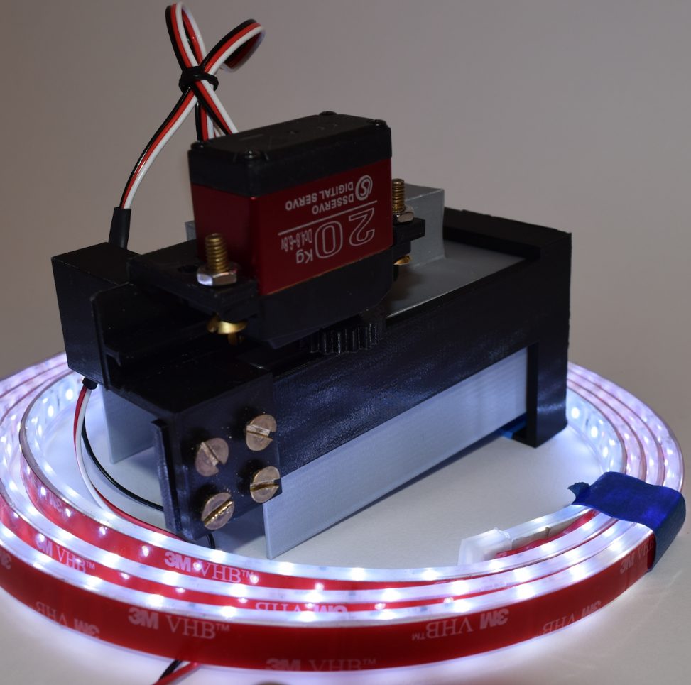
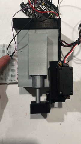
This overall photo shows all components of the project.
This video shows our project in action. When the user grips the photocell and blocks light from reaching it, the system is triggered and it turns on the LED strip and the servo motor rotates to move the toggle switch up. When our device is actually implemented at Joanne’s house the photocell won’t be squeezed by the user, rather the photocell will be focused on a lightbulb that is controlled by Joanne from inside her house.

The LED strip and servo motor assembly are the two main features of this project.
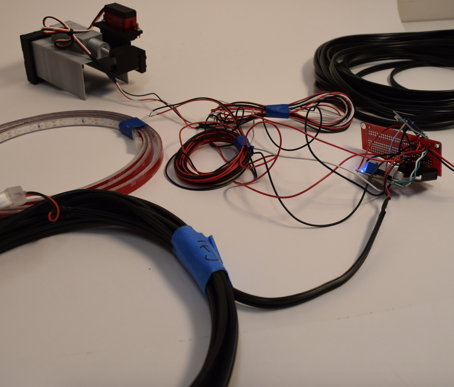
The electronic hardware that deal with voltage logistics and computation are shown in this photo.
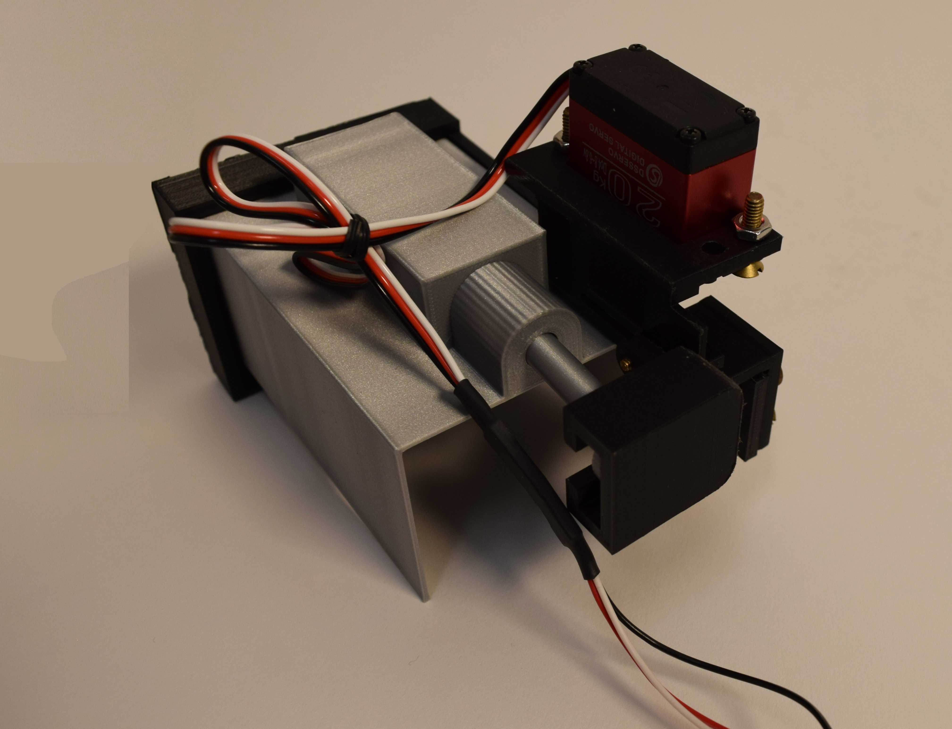
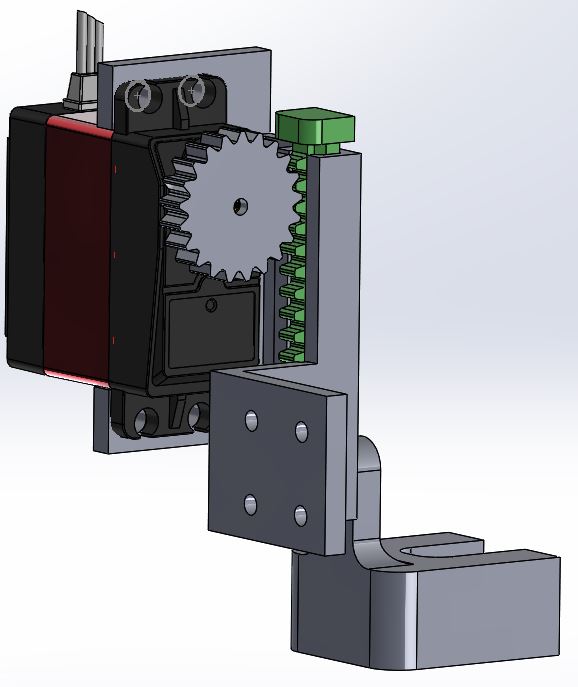
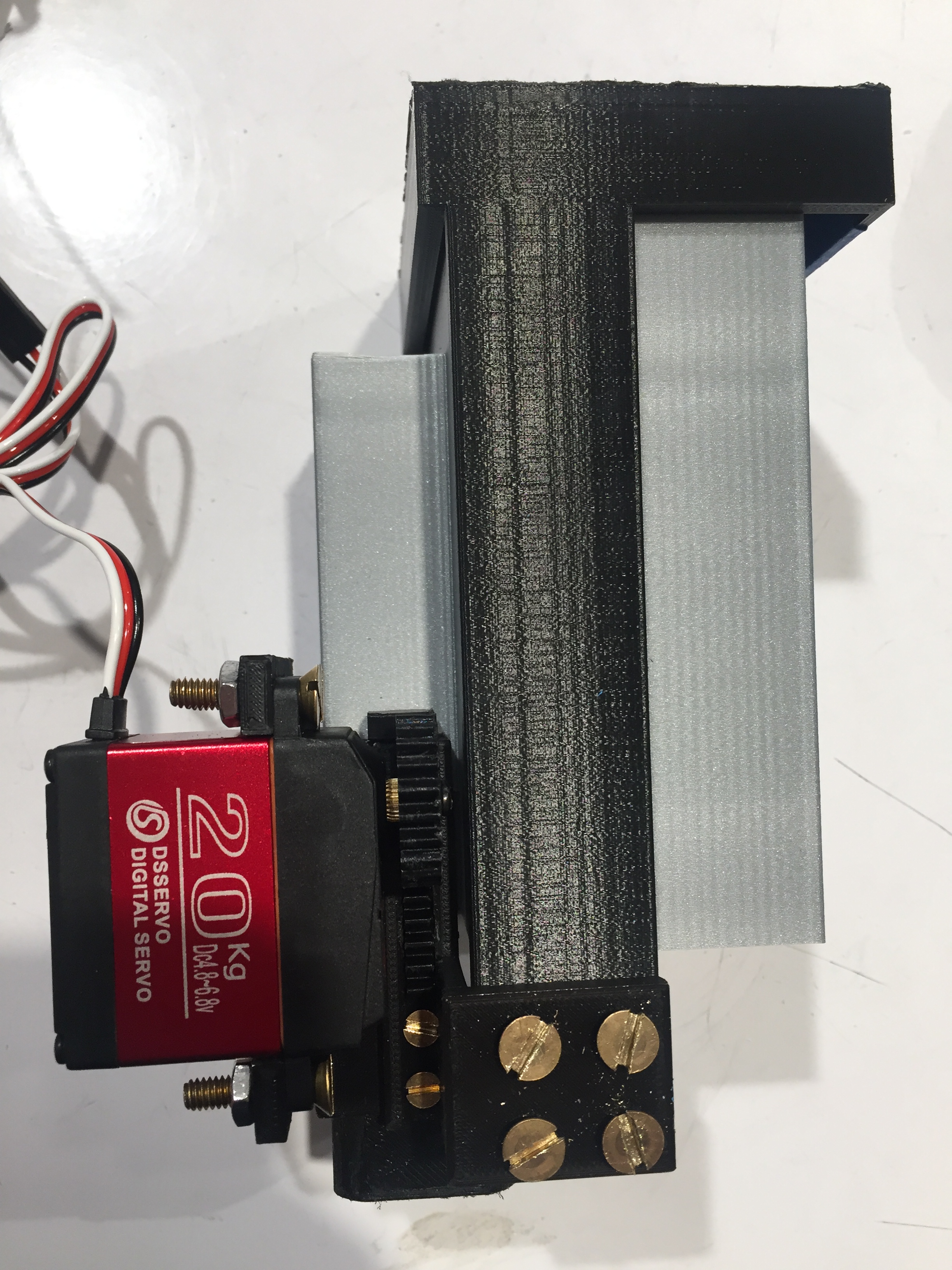
This photo shows the 3D printed assembly that the servo motor operates. The part in grey is a model of Joanne’s linear toggle switch. The part in black is what we will implement at her house to drive the toggle switch.
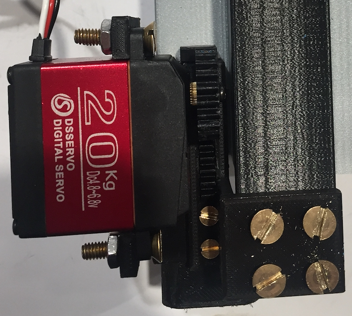
Here is a closeup of the rack and pinion mechanism that is used to translate the servo’s rotational motion into linear. This is an important feature because we are using the servo’s rotational output to activate the toggle switch which requires linear motion.
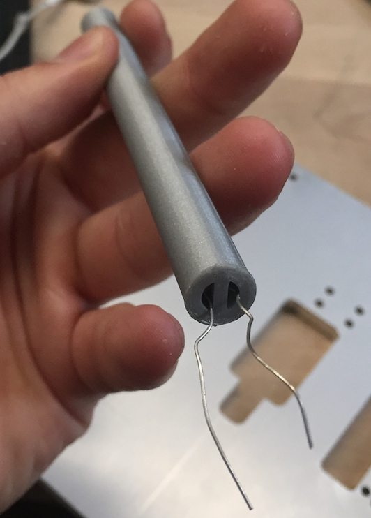
The photocell is placed in a 3D printed housing to focus its view on the lightbulb at Joanne’s house that will be triggering the whole system.
Narrative Sketch
It is a cold winter night and Joanne is in her house when her brother comes home. She wants to turn on her front yard lights for him but one of the front yard lamps is controlled by a switch located outside. She isn’t dressed properly to go outside into the freezing weather conditions. Just as she begins to go put on her warm coat she realizes that two students from Carnegie Mellon just implemented a yard light system that allows her to control all of her front yard lights by a single switch inside. Bursting with delight, she smiles as she flips the switch that controls one of the lamps on her front yard. The photocell that the students place inside of this lamp changes resistance value due to the increased light from the lamp turning on. This triggers her newly implemented yard light system to do two things. One, rotate the servo motor which pushes the linear toggle switch up and turns on the second lamp on her front yard. Two, turn on the LED light strip and light up the previously unlit section of her front yard path. Her brother walks inside and then she flips her control switch again and a split second later all the lights on her front yard are back off.
How We Got Here
After our first prototype we knew we would have to order a lot of parts for the final device. Once essential part was the waterproof servo. Once this arrived the first thing we did was test it.
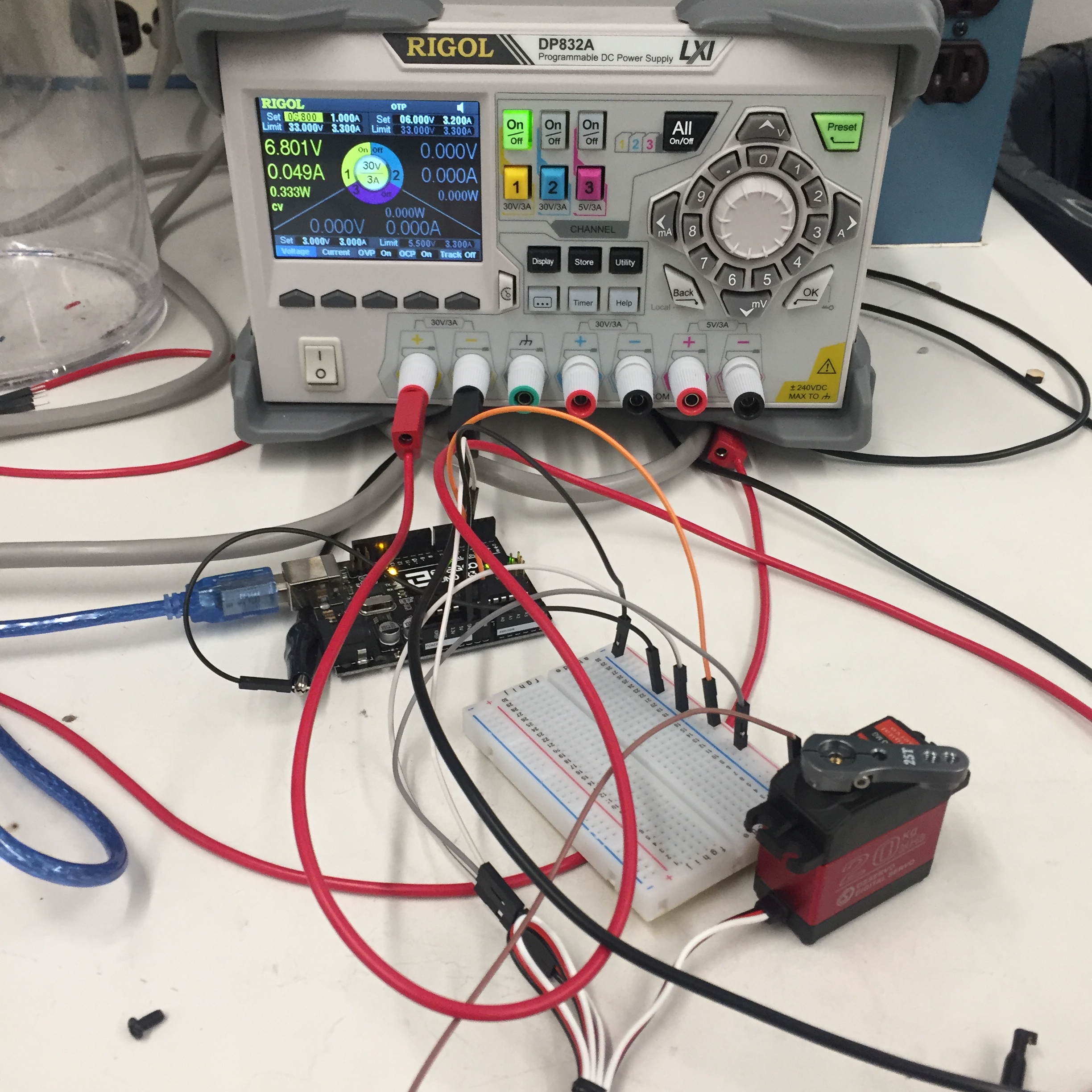
The new servo runs on a maximum of 6.8 volts and we used a power supply to test it.
It was a little different than the servo we were used to using because it had 270 degrees of rotation instead of 180. We knew that we would have to eventually adjust our code to control it but the more challenging problem was to change our mechanical design of our prototype’s 3D printed assembly to fit with the larger dimensions of the new servo. First, we took measurements of the servo and modeled it in SolidWorks.
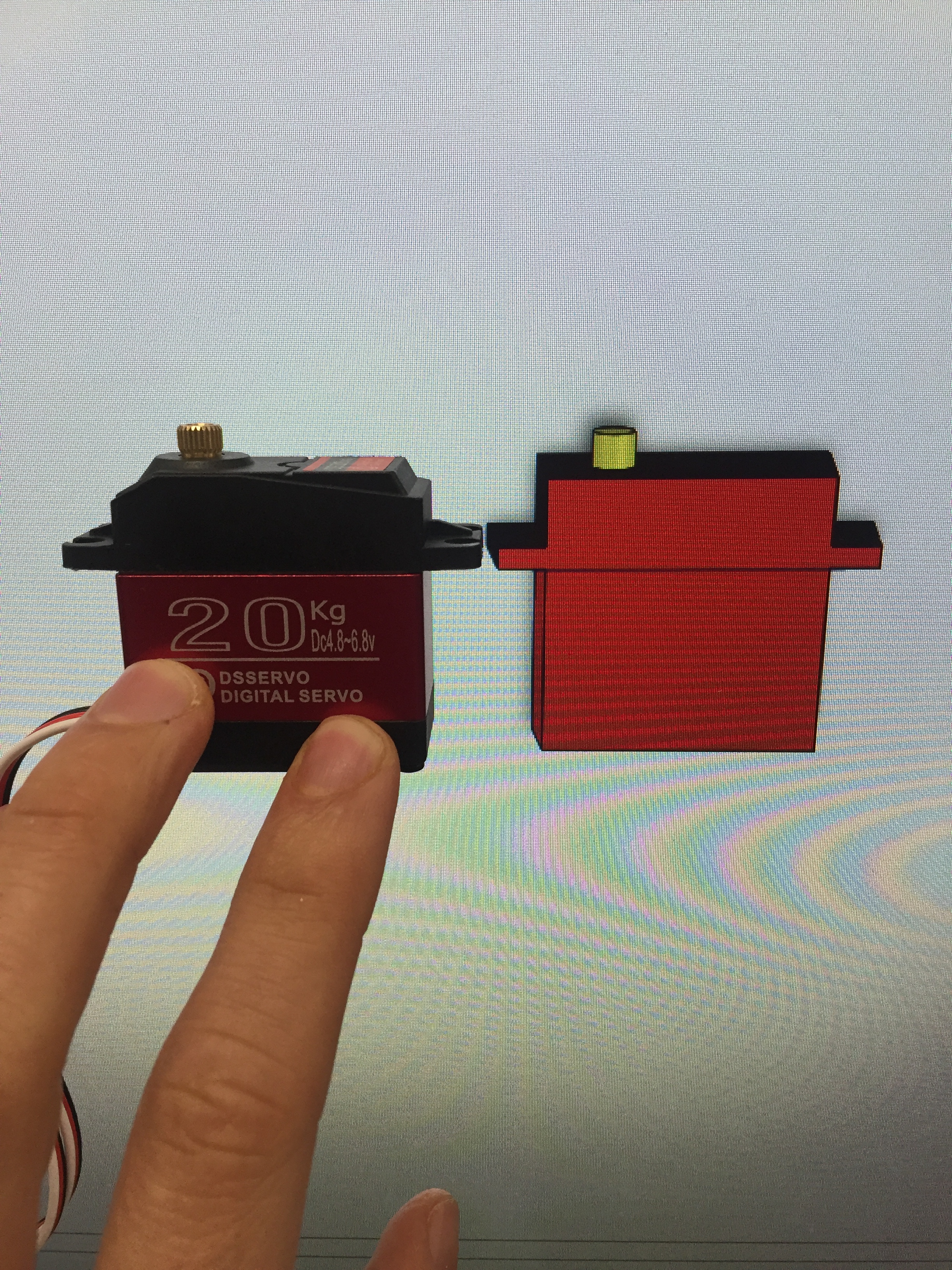
We used a caliper to measure the servo and we only modeled the important features. We ignored all the little fillets and complex grooves.
Although it didn’t take that long to model the servo, it was still time wasted because we later found an exact CAD model on the servo manufacturer’s website. Having the CAD of our servo made it easier to design around. For our new design, we wanted to ensure that we were getting the maximum amount of torque output from our servo so that there would be no issue in terms of strength with moving the linear switch at Joanne’s house. To do this, we had to optimize the size of the gear that would attach to the servo. The smaller the gear, the higher the torque output is. Knowing that the maximum range of rotation for our servo is 270 degrees and that the range of motion for the linear switch is about 0.8 inches, we calculated how small the pitch diameter of our gear could be. We ended up with a pretty small gear that only had 8 teeth on it. It was only after we implemented this new gear into our CAD assembly that we realized the lower bound of our gear size was actually constrained by the width of the servo. Unless we made drastic design changes to our assembly, the gear diameter had to be slightly larger than the width of the servo or else it wouldn’t be able to mesh with the rack. So we designed a larger gear and then moved on to making design adjustments of other parts in our assembly. These adjustments included:
- Slightly reducing the dimensions on the rack for smoother gliding within its track
- Making the grip for the switch bigger and enclosed to maximize the contact area with the switch
- Raising the location of the servo relative to the rack so that it started at the top of the rack and allowed us to optimized the length of the rack.
- Moving the connection point for our rack and pinion assembly from the front face of the switch box cover to the side face.
- Reducing the weight of the rack and pinion assembly by cutting down unused wall space.
- Minor changes to increase structural integrity.
Final assembly of the rack and pinion mechanism that the servo drives.
We also made a significant design change to our switch box cover which is what our rack and pinion assembly will be mounted to. Our prototype cover enclosed the entire switch box. For the final design, we decided that covering the entire switch box was unnecessary and only increased the chances of our cover not fitting properly over the box. So we designed the new cover to be like a small hat for the switch box with a small wall coming down the side for the rack and pinion assembly to be bolted to. This was a minimalist solution to a problem we were very concerned about. The switch box had a lot of protruding bolts, inconvenient fillets, and other complexities induced by deterioration over time. We were worried that even with accurate measurements of the box, these features could throw off the fit of our cover and therefore, cause our switch grip to be misaligned. We think our simplified box cover greatly increases the probability of a proper fit but we still plan to bring some files and other tools with us when we implement our device at Joanne’s house in case additional adjustments need to be made.
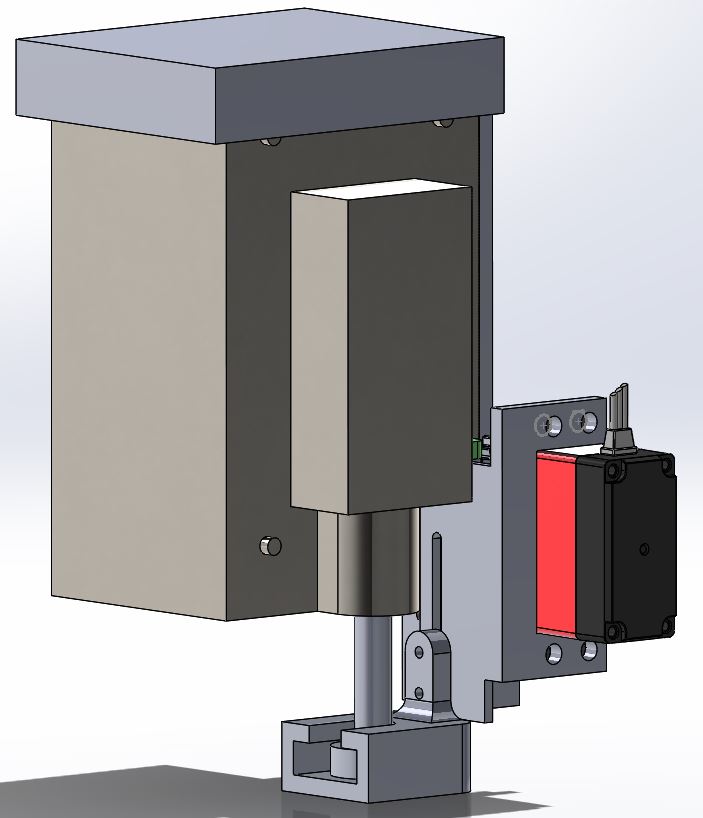
Full assembly of Joanne’s linear toggle switch and the device that we designed to control this toggle switch. The part that is a darker grey shade plus the cylindrical component coming out of the bottom of it is a model of Joanne’s switch. The rest is what we will be implementing.
We used an Ultimaker to 3D print all of our parts.
Full assembly of our 3D printed parts. The part in grey is a model of Joanne’s switch and the parts in black constitute our solutions to controlling this switch with a servo.
To test the performance of our assembly we made a simple circuit to control the servo with a push button.
Our solution to control the linear toggle switch was now complete. We then moved onto the other main component of our project: controlling the LED light strip. We first hooked up our LED strip to a power supply to ensure that it was working.
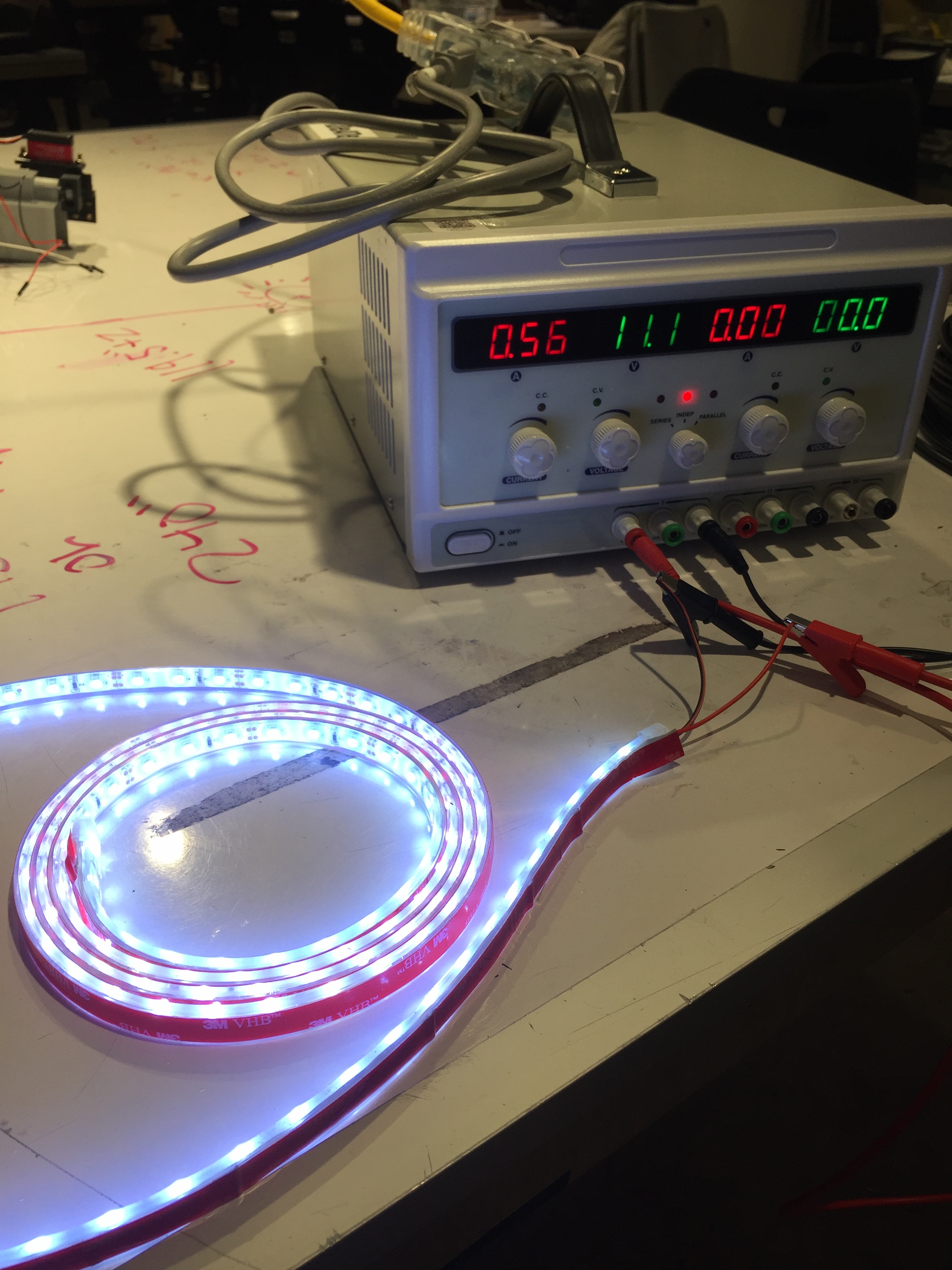
Our LED strip runs on 12 volts. The lights are a cool white color.
We used an n-channel mosfet to turn on and off the LED strip. We were unsure about how to properly use a mosfet so we did a little research online and made a simple circuit on a breadboard and tried a few different configurations until it worked.
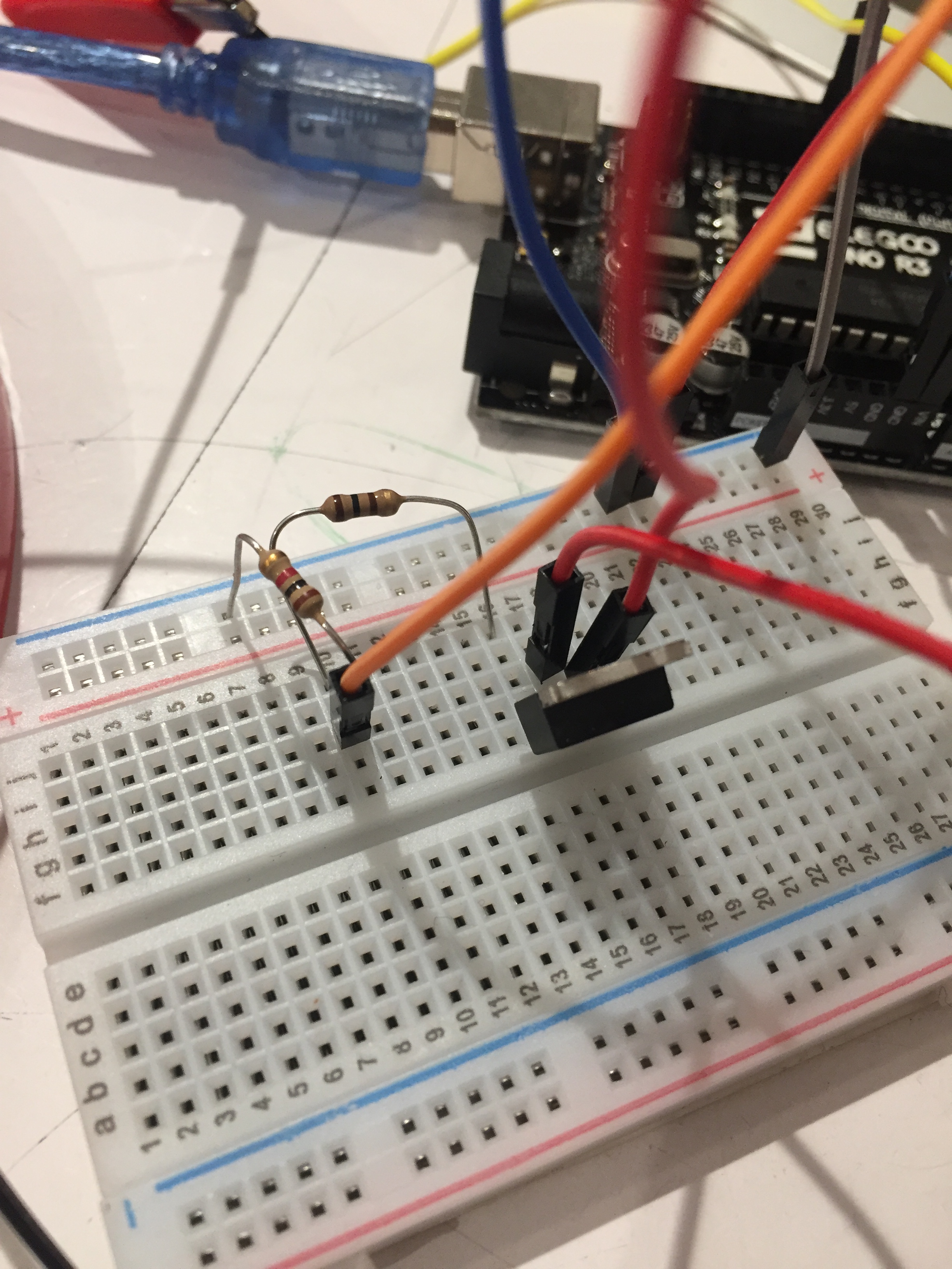
Test circuit using our mosfet.
With all of our hardware and electronic components properly working, we could then integrate everything together. To do this we first had to cut our electrical cords and wires to the proper lengths dictated by the measurements we had previously taken of Joanne’s front yard. To determine these lengths, it helped to visualize the layout of our entire system so we drew a rough sketch of it on a table.
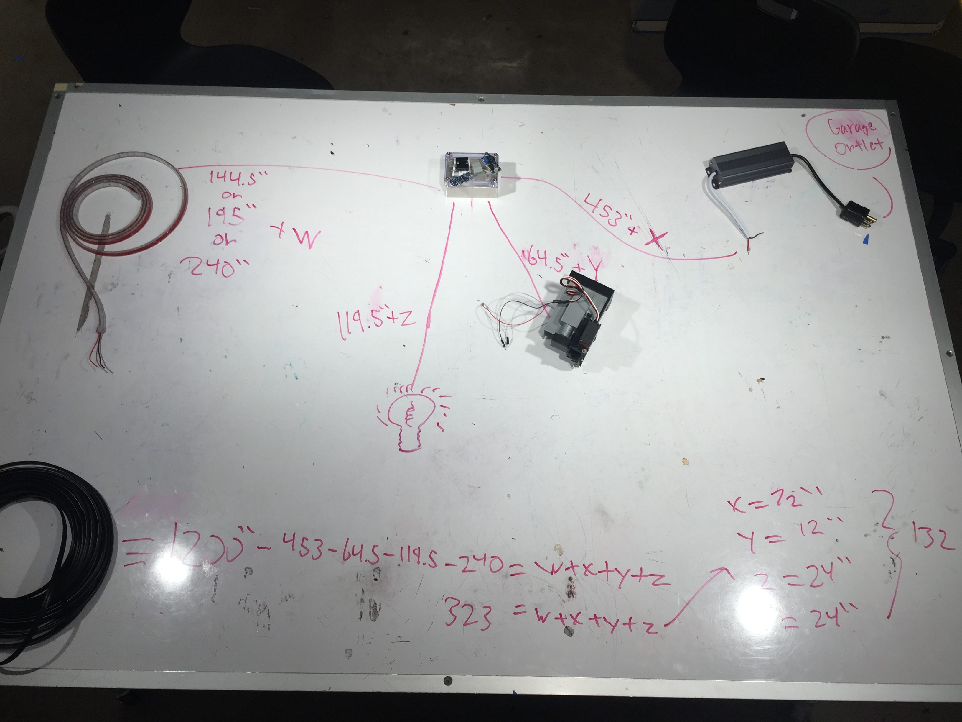
Each component was methodically placed on the table to be in the relative position that they would be when we actually implement the entire system at Joanne’s house. This diagram helped us determine the four different cord lengths that we needed.
We cut the electrical cords to conservative lengths and then we were ready to solder everything together. We soldered a few connections but before long, it became hard to keep track of everything so we drew another diagram to visualize the entire circuit.
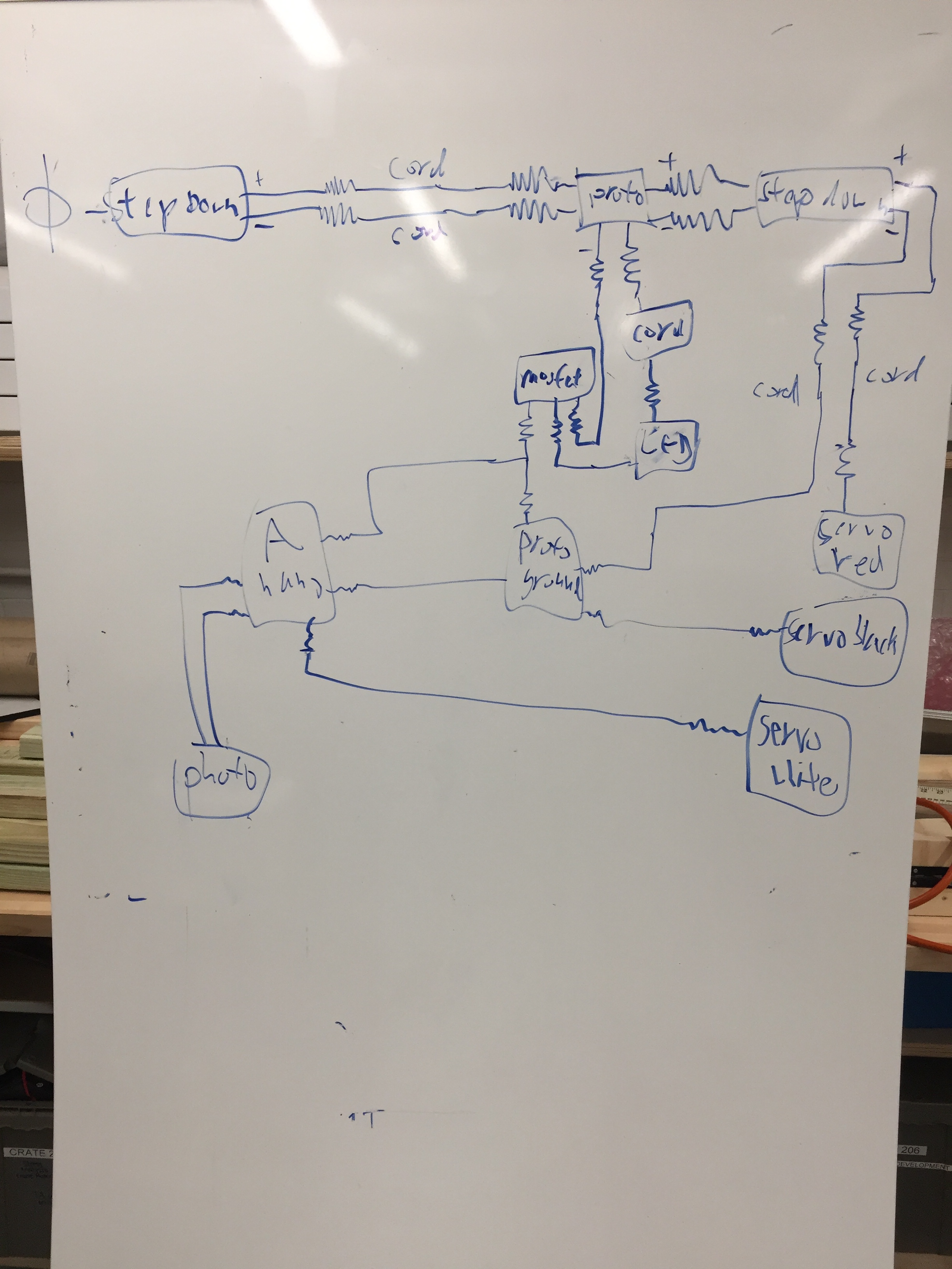
This diagram gave us a visual of almost all the connections that needed to be soldered.
We spent a whole night soldering but by the morning our circuit was complete and all components were working properly.
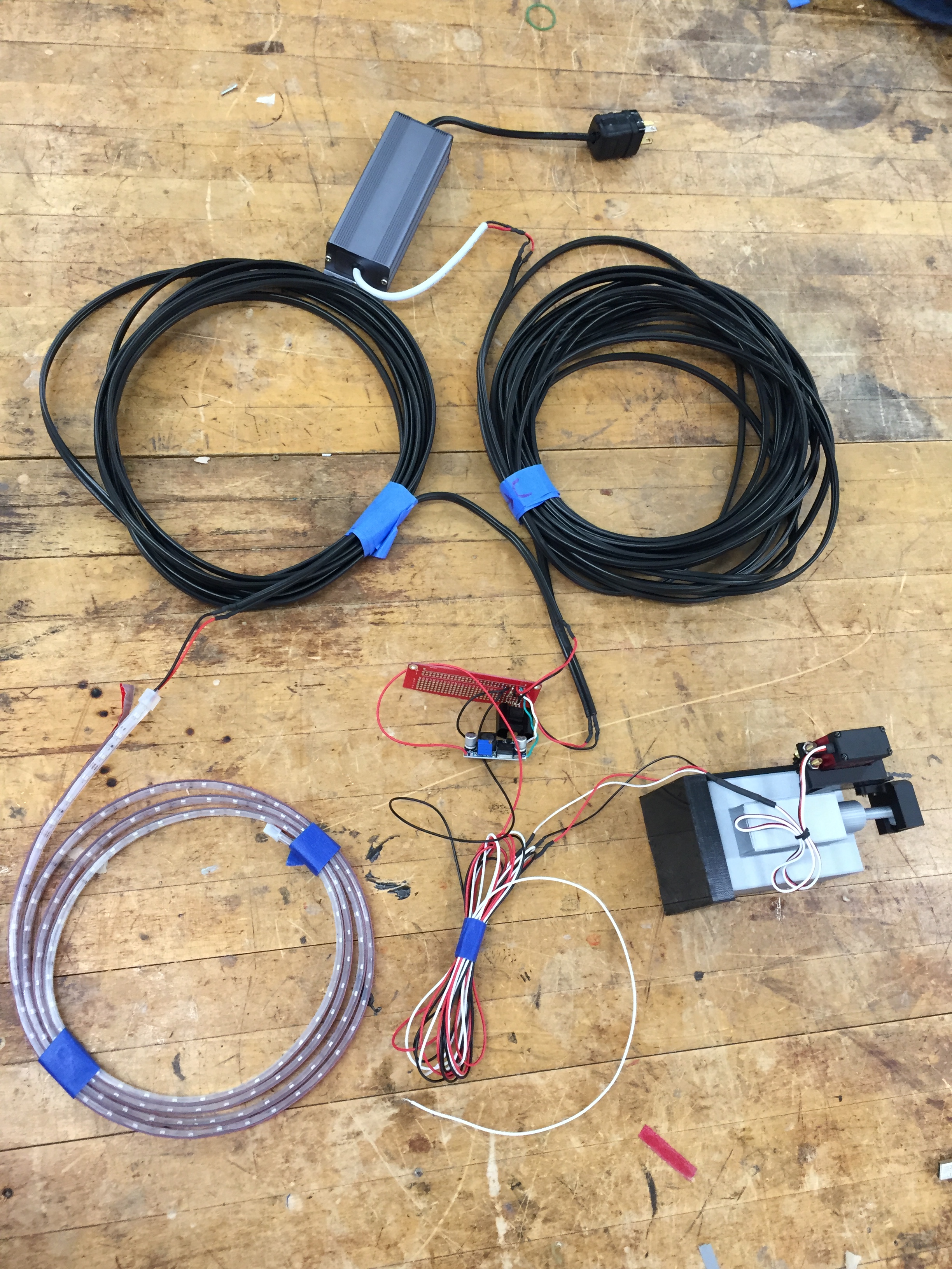
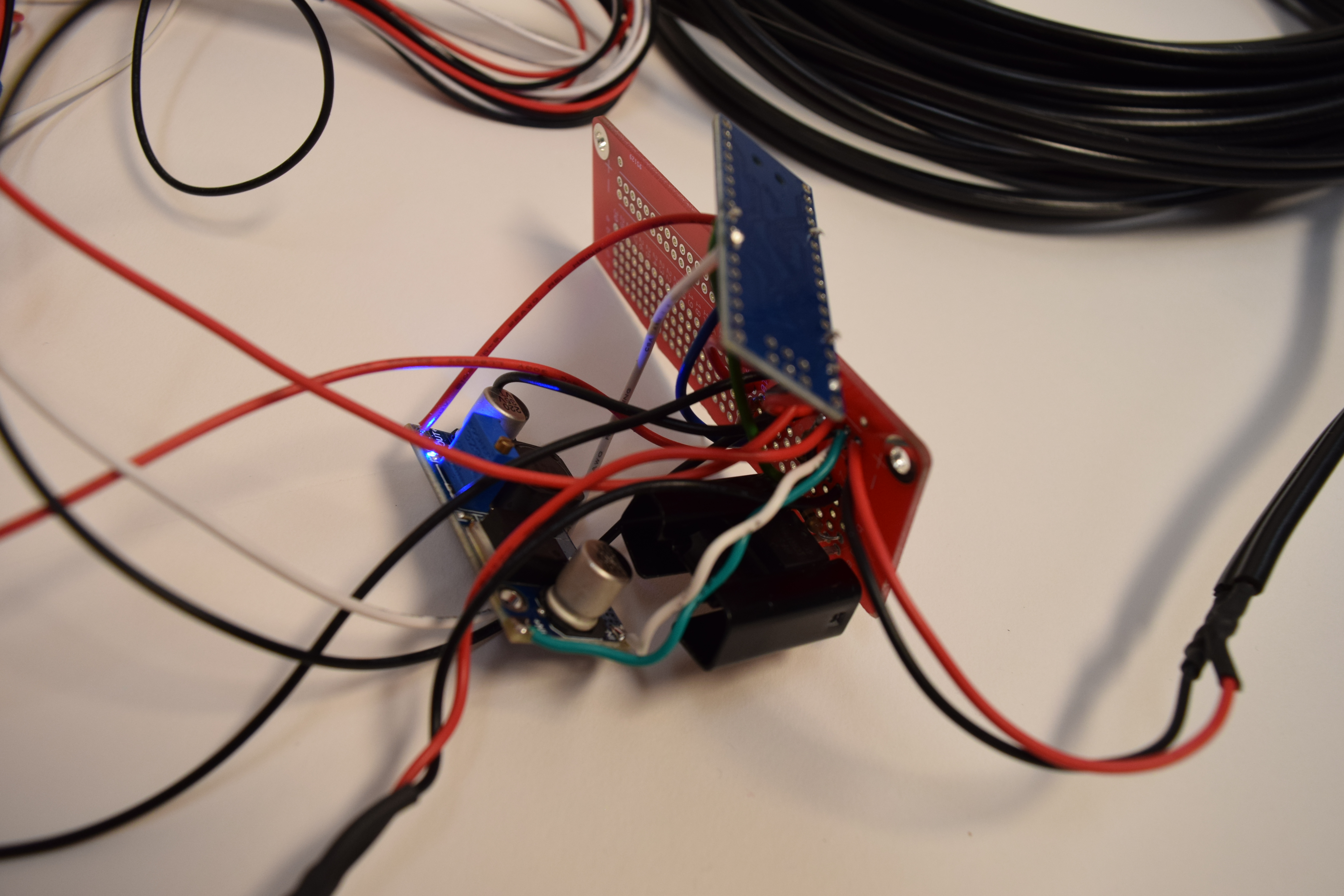
Completed circuit with all connections soldered.
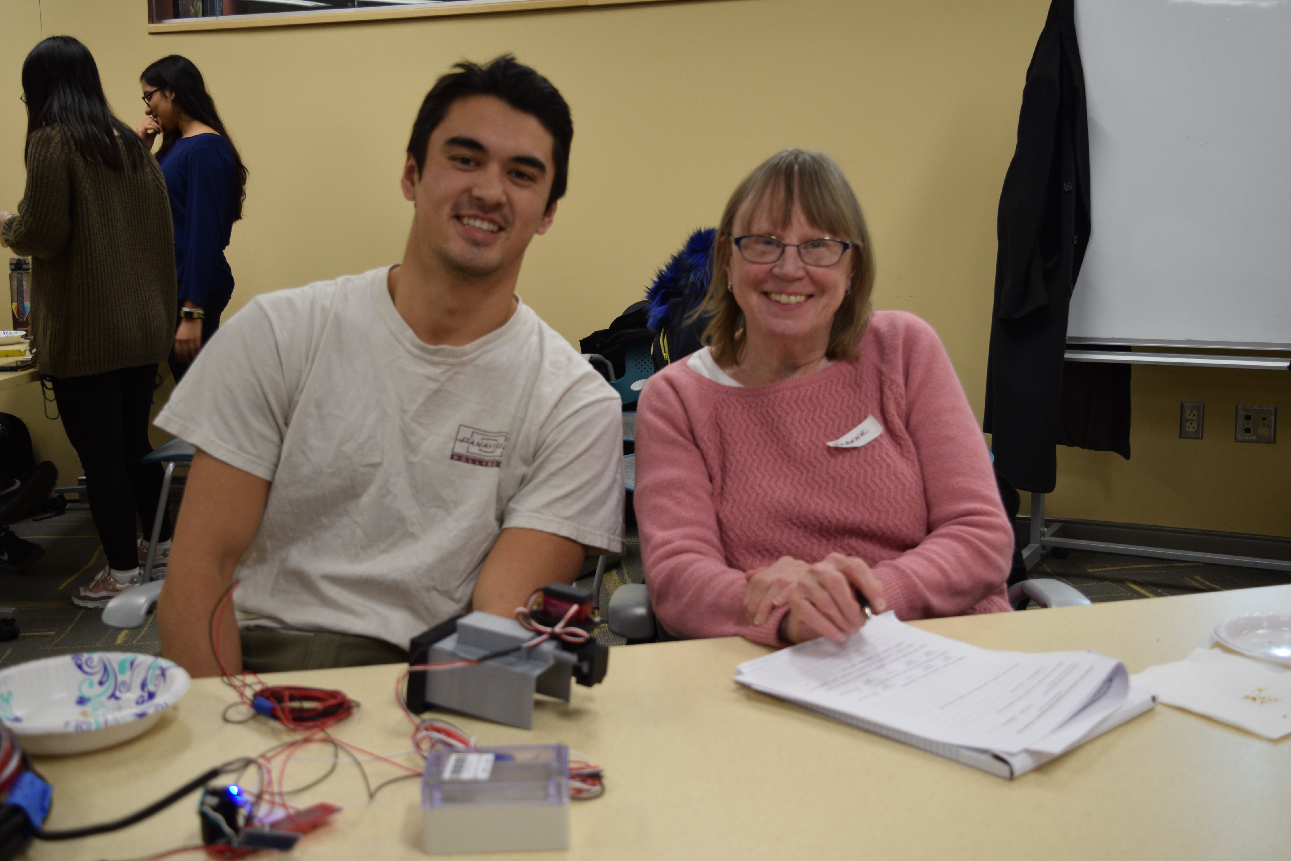
Joanne and Rory at the final crit. Claire unfortunately could not be present because she got very sick the night before.
Conclusions and Lessons Learned
From the final crit we added two major changes and one minor one. The first being a potentiometer which told the code what number was the threshold between night and day. This was a simple addition until the Potentiometer was accidentally plugged into 12v and not the 5v. This broke the Arduino Nano and it had to be removed and a new one soldered in its place. The second major point was allowing Joanne the ability to choose what turning on her front porch light would trigger: the LEDs, the lever, both or none. The simplest method to complete this is having two switches, on representing the lever and one representing the LEDs. If both are switched off turning on the front porch light does nothing. If both are switched on turning on the front porch light triggers both. A challenge was incorporating this addition into the design that would maintain integrity in the weather. A decision was reached that the switches will mount through the top of the waterproof box. The final slight adjustment was making use of the other half of the breadboard by adding indicator lights, a set for daytime and nighttime, a set for the lever pushed and pulled and a set for when the LEDs were on and when they were off in order to help with install and troubleshooting.
From the final crit we received approval from many people. One person said that our device “really solved the problem” and that this could be adapted to solve a similar problem he is having. He was concerned that the “connections seem delicate and could malfunction”. This brings us to our discovery on how critical visual communication was (see the next paragraph). I believe the delicate parts he referred to were the small thin wires on the breadboard itself, something that would be protected by the waterproof box and since the waterproof box wasn’t present at the crit his concern makes sense. But maybe he was psychic and detected the problem that took Zack and Claire a good hour to figure out why the system suddenly electrically stopped working.
Many others shared the concern of weatherproofing and durability.
Some honorable mentions:
“This would be applicable in my home, but I don’t live in a house”
“Good luck installing it :)”
“A creative solution that I will really appreciate”
Something that was a major communication bump early in the process was the first showing of the prototype. Because we lost a group member and a part of the project along with her, we attached a button to the breadboard to show the motor being triggered. Without the photoresistor giving the visual information we were trying to communicate the idea didn’t get across easily. Instead the visual of the button trumped the verbal explanation. The big takeaway was to be as straightforward and simplistic in the explanations for the best possibly clarity. Next time we would have jumped immediately from the final crit to an analysis of the next step, purchasing the switches and getting it ready for installation. Since we waited till the weekend we were unable to install in time and pushed the date back to January. If we could do anything differently it would be Claire not needing to go to the E.R. the night before the project was due.
The overall takeaway is that there is always something you overlook and time needs to be allotted for the mistake. Successfully managing a project is not defined in the ability to predict mistakes but to accommodate for them.
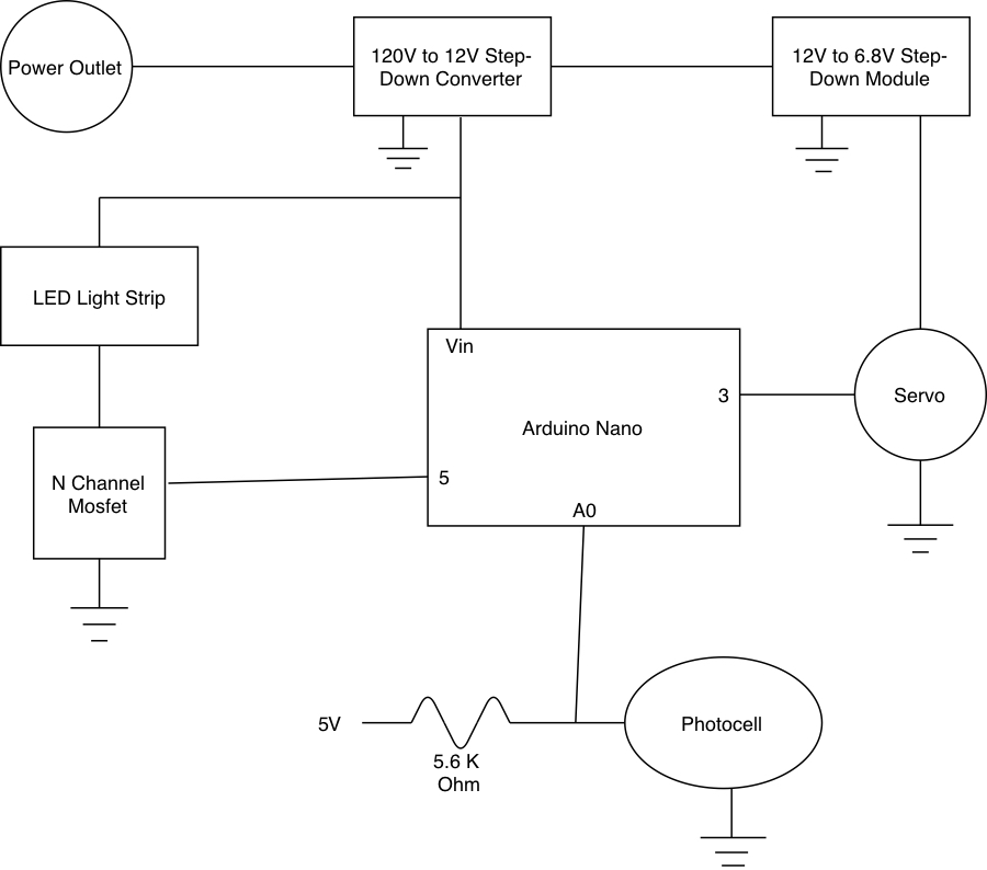
Schematic
Code
/*
 * Yard Lights
 * Claire Mildred and Rory Hubbard
 *
 * This code activates and LED strip and a servo motor depending on a reading
 * from a photocell. When the photocell reading is below a certain threshold
 * the LED strip will be turned off and the servo will rotate to the 0
 * position. When the photocell is higher than the threshold the LED strip will
 * be turned on and the servo will rotate 80 degrees. No rights reserved.
 *
*/

#include <Servo.h>
Servo myservo;

// establish pins
const int PHOTOCELL_READ = A0;
const int LED_CONTROL = 5;

// establish photocell threshold value to turn on or off the system
const int THRESHOLD = 800;

bool down; // this variable will keep track of the position of the servo
int photoVal; // initialize a new integer to store the photocell value

void setup() {
  pinMode(PHOTOCELL_READ, INPUT);
  pinMode(LED_CONTROL,OUTPUT);
  myservo.attach(3,500,2500); // pulse width range of this servo is 500 - 2500
  // microseconds
  myservo.write(0); // start with servo down
  down = true;
  //Serial.begin(9600);
}

void loop() {

  photoVal = analogRead(PHOTOCELL_READ); // acquire a reading from the
  // photocell every loop
  // Serial.println(photoVal);

  if (photoVal >= THRESHOLD && down == true) {
    myservo.write(80);
    down = false; // servo has moved the toggle switch up
    digitalWrite(LED_CONTROL,HIGH); // turn on LED strip
    delay(100); // little delay to deter flickering and allow servo to reach
    // final position
  }

  else if (photoVal < THRESHOLD && down == false) {
    myservo.write(0);
    down = true; // servo has moved the toggle switch down
    digitalWrite(LED_CONTROL,LOW); // turn off LED strip
    delay(100); // little delay to deter flickering and allow servo to reach
    // final position
  }

  // no else statement because we only need to write to our servo and LED's
  // one time when it changes state

}
Leave a Reply
You must be logged in to post a comment.