Color to Rotational Position
Our double transducer took color as an input, transforming it into rotational position.
The final double transducer, copy 1.
The second copy of the double transducer we made.
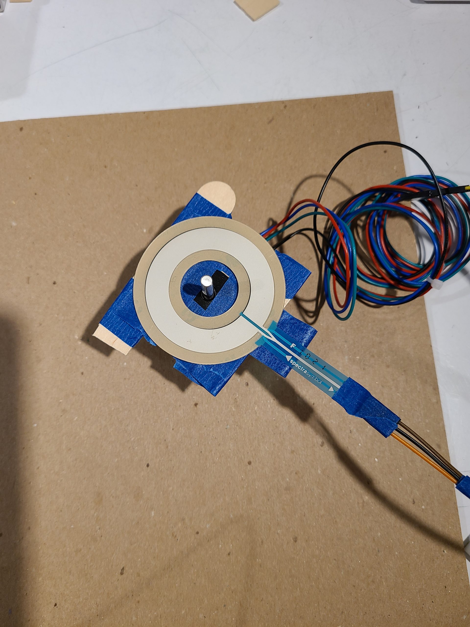
The first part is the color sensor (at the top of the images), which reads what color is put in front of it. After turning it on, we make sure the color sensor is at the correct position, so we have to put a color in front of it and press the button, which makes 1/10th of a full rotation, until the color sensor is pointing to the correct location on the color wheel. When a different color is put in front of the color sensor, the color sensor reads the color and spins the motor to point to the color we are reading. The position of the motor puts pressure on a different sensor. Depending on what location the second sensor is being pressed, the final motor turns a certain amount.
Detail Shots
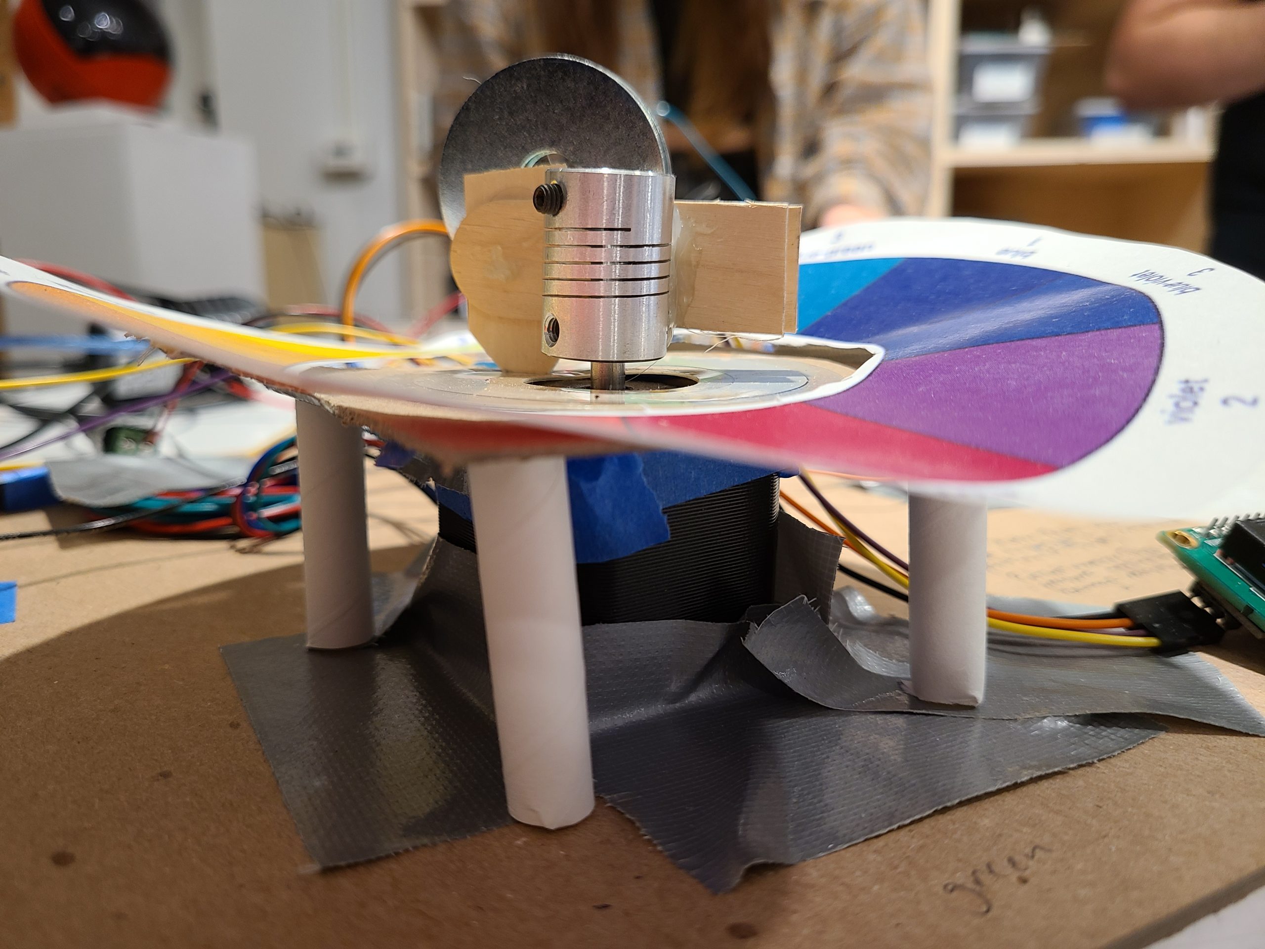
Detail shot: the small pillars we added in order to stabilize the potentiometer input.
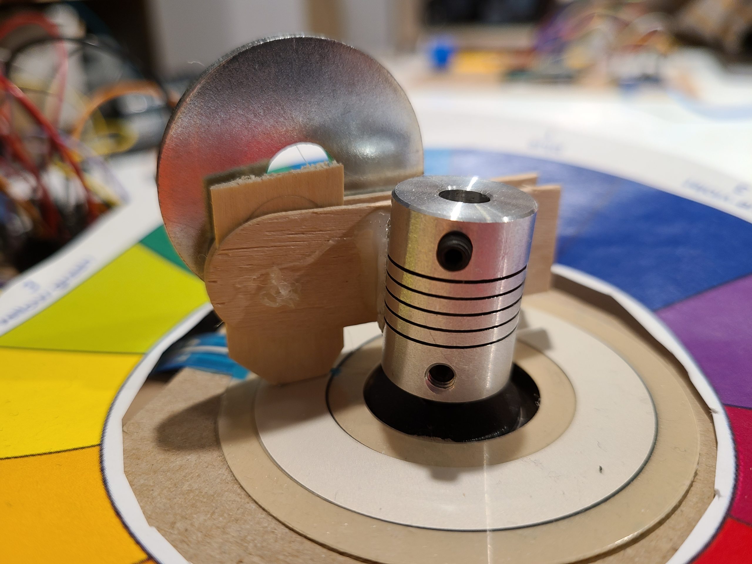
Detail shot: the arm attached to the stepper motor which puts pressure on the potentiometer.
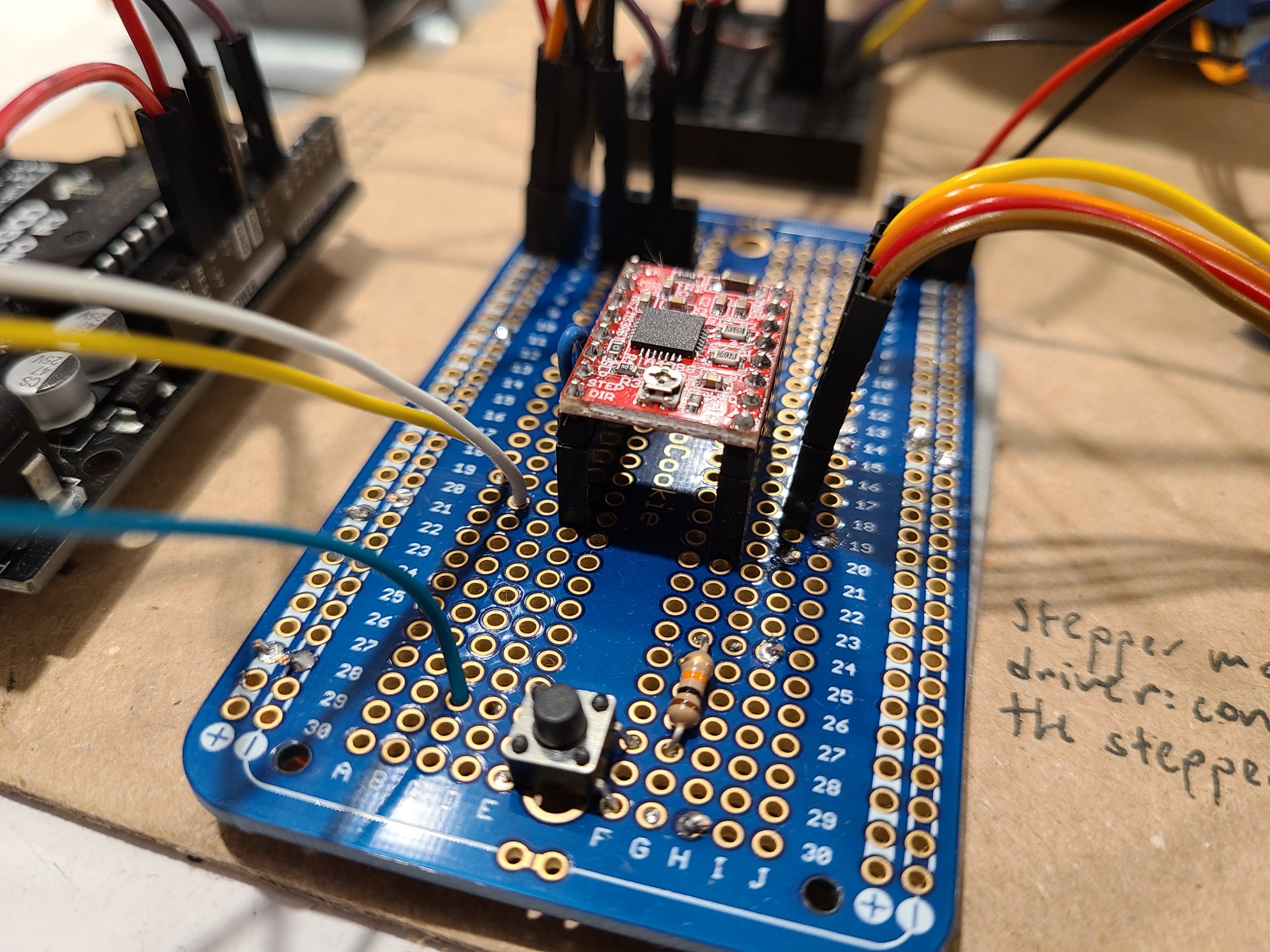
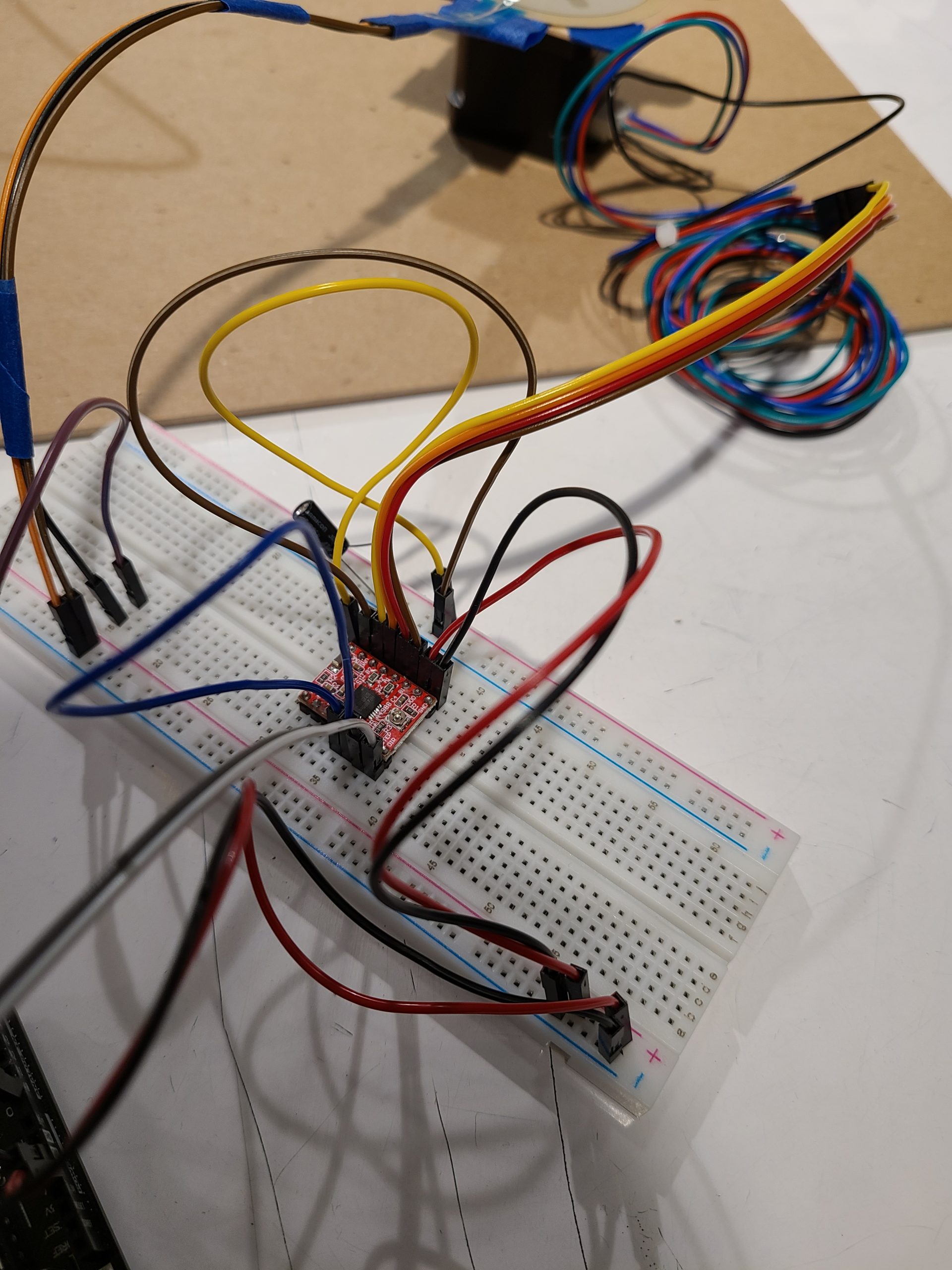
Detail shot: the soldered board.
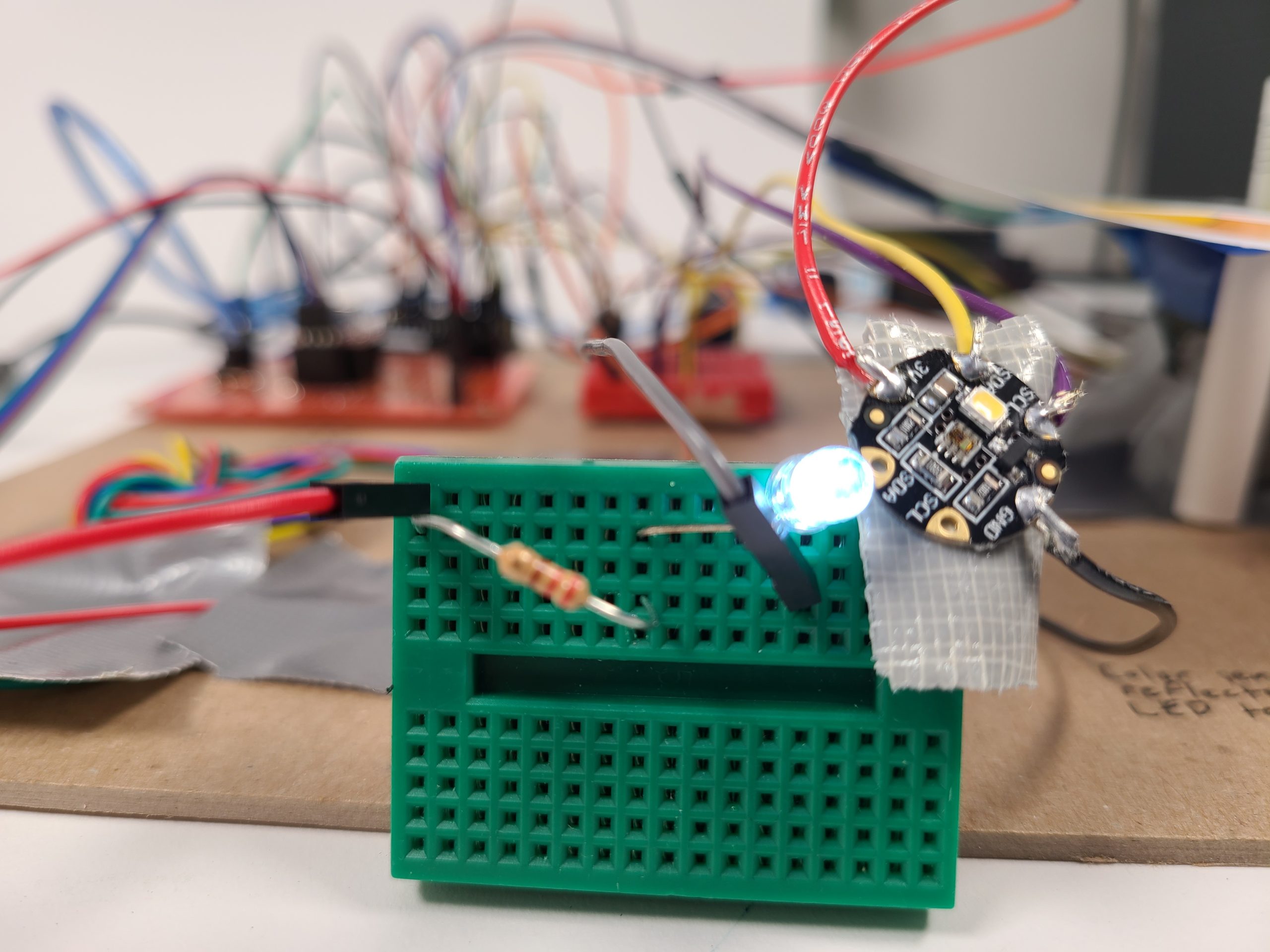
Detail shot: The second color sensor, with a busted LED that we had to replace.
Progress Images
Our day 1 design for the potentiometer. Unstable, ultimately redone.
First attempt at getting the stepper motor to work
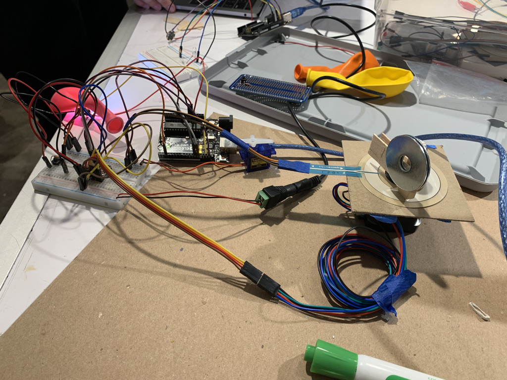
First working color sensor to stepper motor rotation to potentiometer read

Finished the soldering on the first board, and verified that the motor works.
Discussion
The first day we spent the entire two hours of class trying to work with the force sensing circular potentiometer, trying to get a consistent reading on it. We fiddled with it for ages, trying to find something that could move and apply enough pressure to the potentiometer for it to consistently register. Our first attempt at this was to add weights to the pointer part of the arm that would apply pressure. However, by the end of it, it still wasn’t working, and we had to consider our options. We came up with a few: first, we could continue working with the potentiometer, with our next steps being that we would move it to a more stable surface; and two, we could create what was basically our own potentiometer by moving a stepper motor with resistors surrounding it and measuring the change in voltage. However we did end up making the circular potentiometer work by creating a more stable surface, and adding support beams and weights to the arm. This was definitely the hardest part of the project.
Something that initially seemed fairly daunting, was soldering. Neither of us had much experience with soldering in the past, and the number of pins that needed to be soldered to run the stepper motor was very scary. However, after the first 10-15 pins, the we picked up a feel for how to work the soldering iron and make pretty solders. The second board soldering process went by much faster, and overall would say that soldering feels fairly easy now especially considering where we started.
One decision that would have changed everything about what we learned and how cool our project ended up being, is using the easy middle step that we had initially discussed. One of our three initial ideas was to use the brightness of a bulb to change a photoresistor resistance and measure that change. We would have had a much easier soldering step, which means we would likely not have been as comfortable as we are now with it, and it also would have removed the entire centerpiece of our final design, which was the color wheel to stepper motor interaction that lets us display color.
Functional Block Diagram
![]()
Schematic

Video
A video demonstration of the color wheel working. There is a slight delay between the color input and the movement of the motors; this is due to the calculations made to get the raw data from the sensors.
Code
/*
Double Transducer: Color to Rotational Position

1. Reads values from the color sensor,
2. Converts it into a degree value based on the color sensed from the color sensor
3. Moves stepper motor stepwise until it reaches the number of degrees we got from the color sensor
4. Reads potentiometer reading
5. Translate potentiometer reading into an amount to move the final servo motor

Credit: https://www.py4u.net/discuss/63122 for the code to convert rgb values to hsv values
*/
#include <AccelStepper.h>
#include <Servo.h>
#include <Wire.h>
#include "Adafruit_TCS34725.h"
#include <LiquidCrystal_I2C.h>


const int STEP_PIN = 12; // A4988 "STEP" pin wired to Arduino pin 2 for stepper
const int DIR_PIN = 13; // A4988 "DIRECTION" pin wired to Arduino pin 3 for stepper motor
const int buttonPin = 2; // pin for button press
const int servoPin = 3;  // pin for controlling servo motor
Adafruit_TCS34725 tcs = Adafruit_TCS34725(TCS34725_INTEGRATIONTIME_614MS, TCS34725_GAIN_1X);
LiquidCrystal_I2C lcd(0x27, 16, 2); // initializes

typedef struct {
    double h;       // angle in degrees
    double s;       // a fraction between 0 and 1
    double v;       // a fraction between 0 and 1
} hsv;

static hsv   rgb2hsv(float r, float g, float b);

// converts rgb values to hsv values
hsv rgb2hsv(float r, float g, float b)
{
    hsv         out;
    double      min, max, delta;

    min = r < g ? r : g;
    min = min  < b ? min  : b;

    max = r > g ? r : g;
    max = max  > b ? max  : b;

    out.v = max;                                // v
    delta = max - min;
    if (delta < 0.00001)
    {
        out.s = 0;
        out.h = 0; // undefined, maybe nan?
        return out;
    }
    if( max > 0.0 ) { // NOTE: if Max is == 0, this divide would cause a crash
        out.s = (delta / max);                  // s
    } else {
        // if max is 0, then r = g = b = 0
        // s = 0, h is undefined
        out.s = 0.0;
        out.h = NAN;                            // its now undefined
        return out;
    }
    if( r >= max )                           // > is bogus, just keeps compilor happy
        out.h = ( g - b ) / delta;        // between yellow & magenta
    else
    if( g >= max )
        out.h = 2.0 + ( b - r ) / delta;  // between cyan & yellow
    else
        out.h = 4.0 + ( r - g ) / delta;  // between magenta & cyan

    out.h *= 60.0;                              // degrees

    if( out.h < 0.0 )
        out.h += 360.0;

    return out;
}

Servo serv;

// make an AccelStepper motor object.
AccelStepper myMotor(1, STEP_PIN, DIR_PIN);

long long count = 0;
long total = 0;
long sampleSize = 0;

int calibPos = 0;
int pos = 0;
long long setPosTimer = 0;
long long buttonTimer = 0;

long long
int degree = 0;
char color[20];


void setup(){
  Serial.begin(9600); // begin Serial communication
  pinMode(buttonPin, INPUT);
  //checks color sensor is working
  Serial.println("setupr");
  if (tcs.begin()) {
    Serial.println("Found sensor");
  } else {
    Serial.println("No TCS34725 found ... check your connections");
    while (1);
  }

  // starts the display
  lcd.begin();
  lcd.backlight();
  lcd.print("Hi!");

  // you can change the below values as you'd like
  myMotor.setMaxSpeed(150); // measured in steps per second
  myMotor.setAcceleration(50); // measured in steps per second squared
  serv.attach(servoPin);

  setPosTimer = millis();
  myMotor.moveTo(0);

  while(myMotor.distanceToGo() != 0) {
    myMotor.run();
  }
}

void loop(){
  // calculates color input
  if (millis() - setPosTimer >= 5000 && millis() >= 10000) {
    uint16_t r, g, b, c;
    tcs.getRawData(&r, &g, &b, &c);
    float red, green, blue;
    tcs.getRGB(&red, &green, &blue);


    red = red / 255;
    green = green / 255;
    blue = blue / 255;

    double h = rgb2hsv(red, green, blue).h;
    int hue = int(h);
    Serial.println(hue);

    if (hue >= 0 && hue < 15) {
      strncpy(color, "red", 3);
    } else if (hue >= 15 && hue < 45){
      strncpy(color, "orange", 6);
    } else if (hue >= 45 && hue < 75){
      strncpy(color, "yellow", 6);
    } else if (hue >= 75 && hue < 150){
      strncpy(color, "green", 5);
    } else if (hue >= 150 && hue < 200){
      strncpy(color, "cyan", 4);
    } else if (hue >= 200 && hue < 255){
      strncpy(color, "blue", 4);
    } else if (hue >= 255 && hue < 285){
      strncpy(color, "purple", 6);
    } else if (hue >= 285 && hue < 315){
      strncpy(color, "pink", 4);
    } else if (hue >= 315 && hue < 360){
      strncpy(color, "red", 3);
    } else {
      strncpy(color, "N/A", 3);
    }
    lcd.home();
    lcd.print("Color: ");
    lcd.print(color);
    strncpy(color, "          ", 10);

    // moves stepper motor
    int stepperTarget = map(hue, 0, 360, 0, 200) + calibPos;
    Serial.print("Current pos and Target pos: ");
    Serial.print(pos);
    Serial.print(", ");
    Serial.println(stepperTarget);
    myMotor.moveTo(stepperTarget);
    pos = stepperTarget;
    setPosTimer = millis();
    lcd.setCursor(0, 1);
    lcd.print("moving to: ");
    lcd.print(stepperTarget);

  }

  // Use button to calibrate without changing pos
  if (digitalRead(buttonPin) == HIGH && millis() - buttonTimer >= 1000){
    Serial.println("Press");
    calibPos += 20;
    myMotor.moveTo(pos);
    buttonTimer = millis();
  }

  // moves servo motor
  if ( count % 100 == 0 ) {
    int servPos = map(total/100, 0, 1023, 10, 90);
    Serial.println(servPos);
    serv.write(servPos);
    total = 0;
  }
  total += analogRead(A0);
  count++;
  myMotor.run();

}