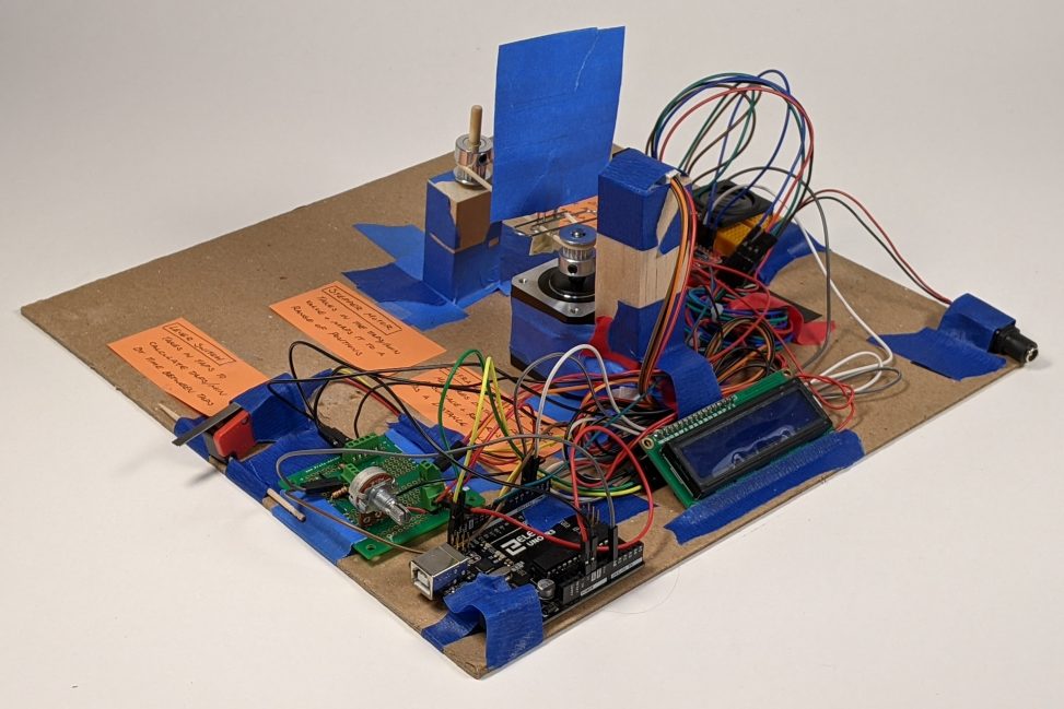
A view of the arrangement of all parts positioned on the 12″ by 12″ board with the switch input on the left and the speaker on the right.
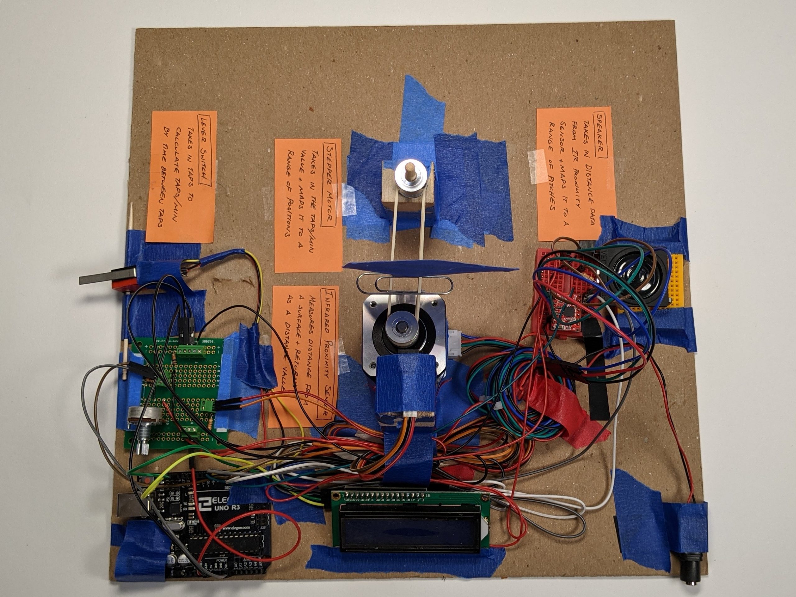
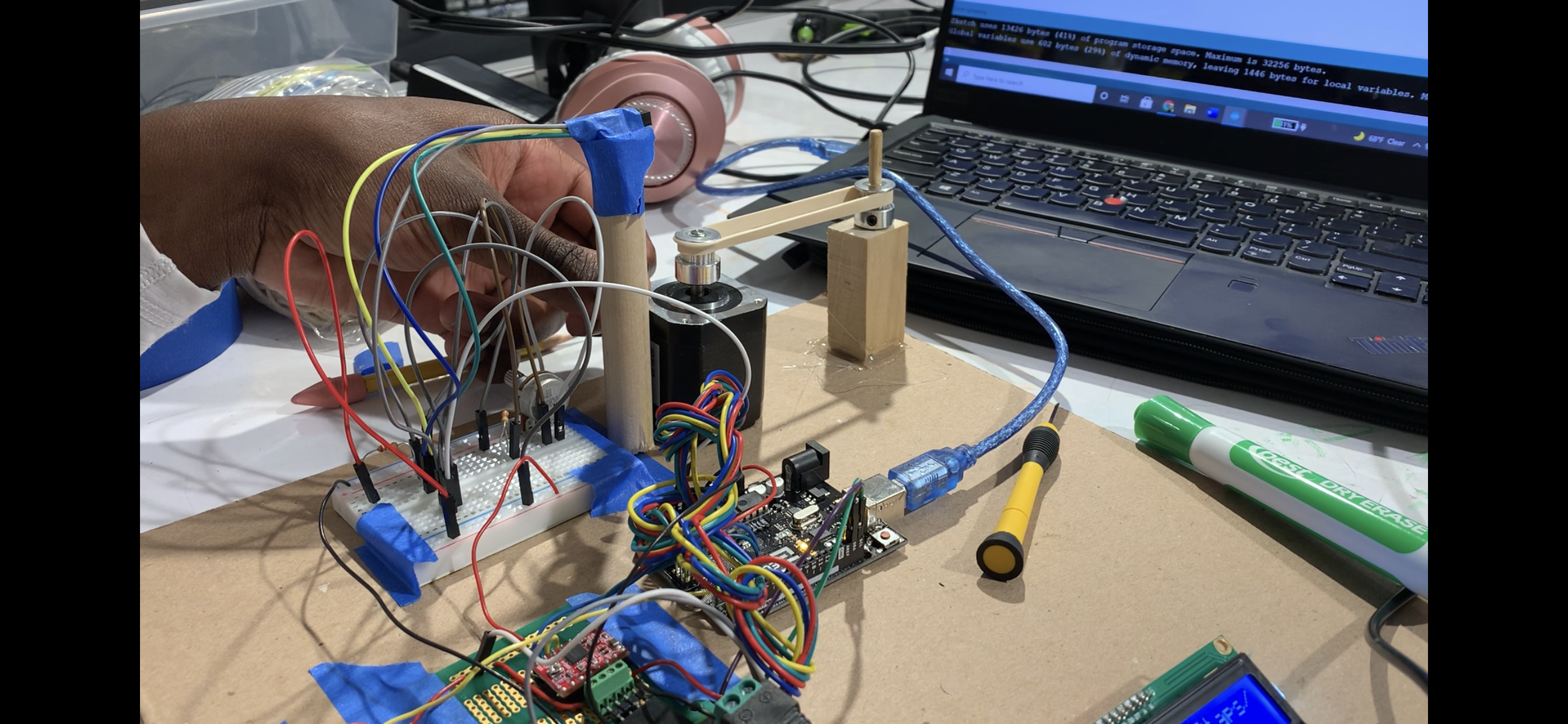
A detailed view of the belt pulley system with the tape board for distance, a stepper motor and corresponding post, and the infrared proximity sensor on top of the block.
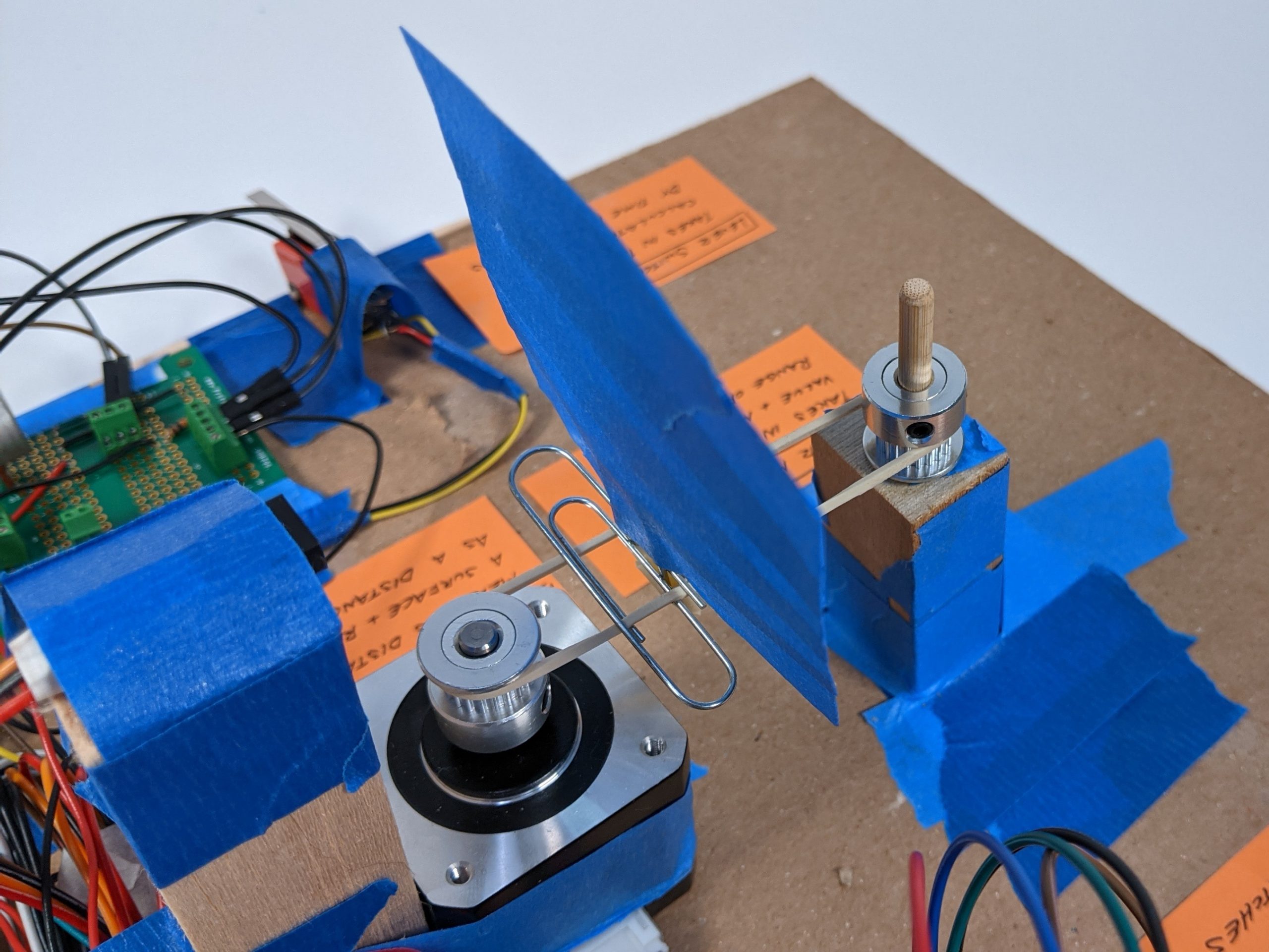
A view of the speaker used.
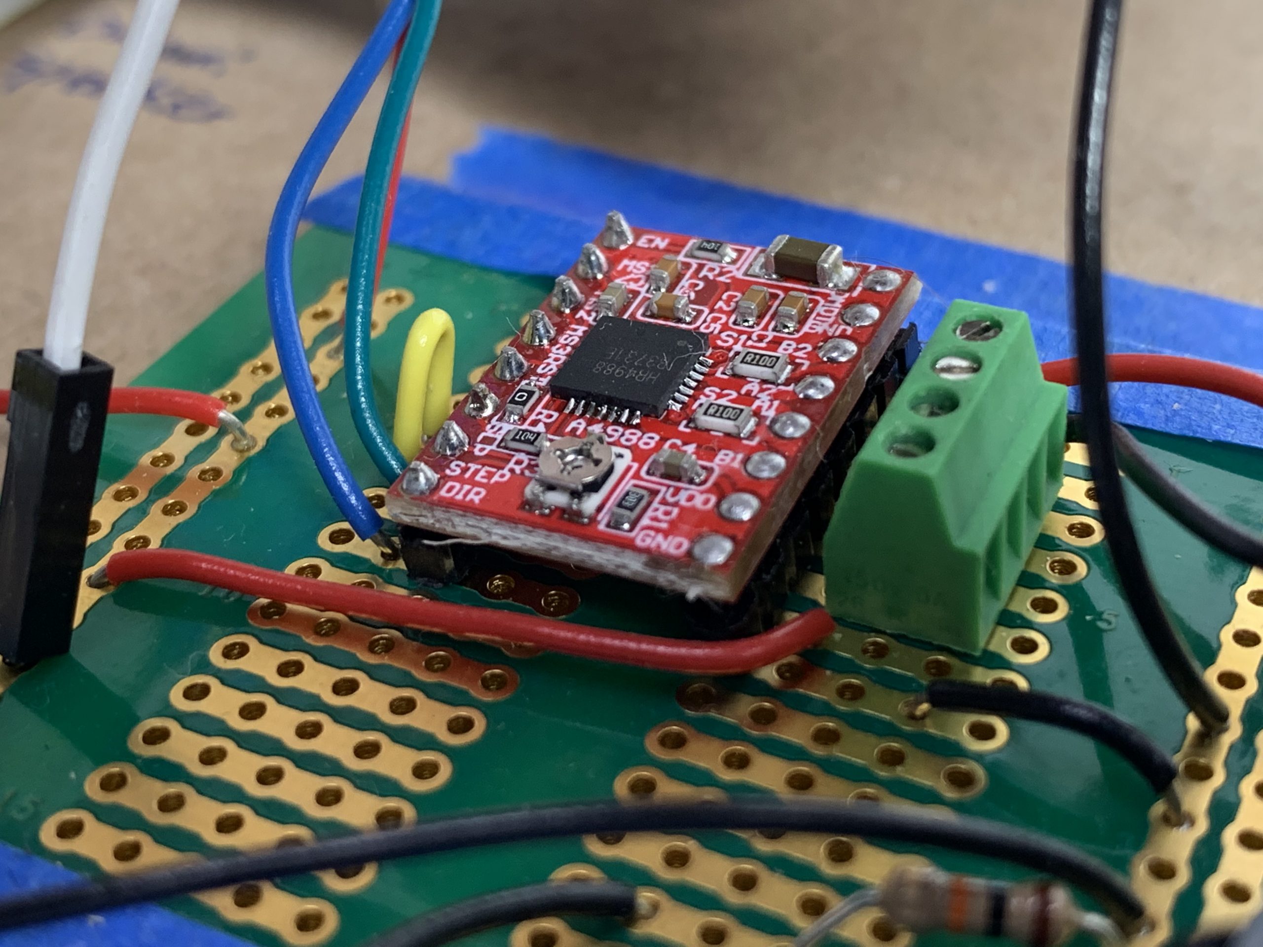
A view of the soldering connections made with the A4988 microstepping motor driver.
Description
A button is on the left edge of the board. In the center, there is a motor, a rubber band with a piece of paper attached to it, and a sensor. On the right edge of the board, there is a speaker constantly playing a sound. The faster the button gets pressed, the more the motor moves the piece of paper on the rubber band toward the sensor. When the paper gets closer to the sensor, the speaker plays a higher-pitched sound.
Process
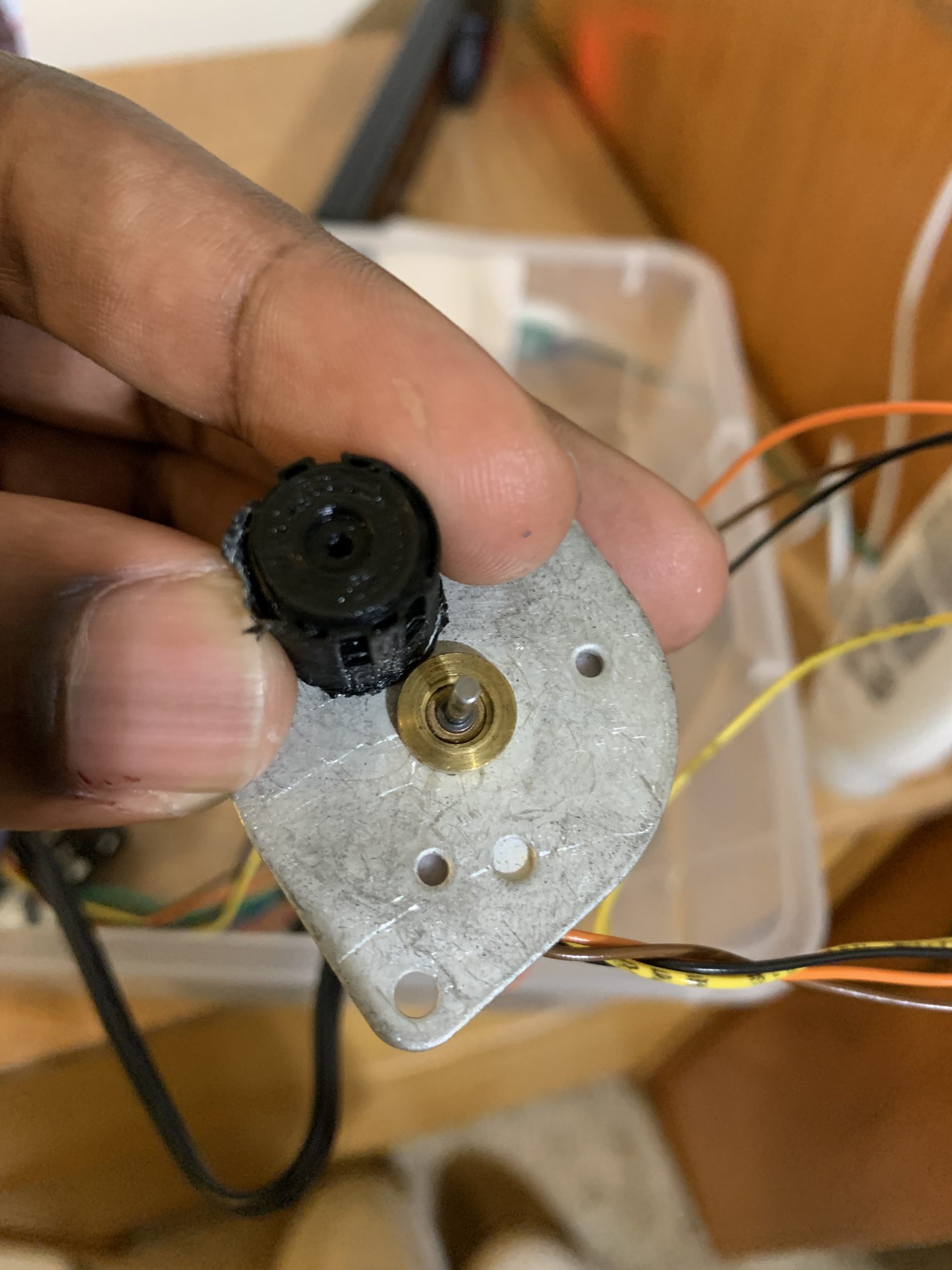
At this stage, we were considering using a smaller stepper motor and attaching a 3D printed part to the shaft. However, the code we ran only worked on the bigger motor and the 3D print was difficult to attach, so we decided to go with the larger motor and find parts that are already in the shop.
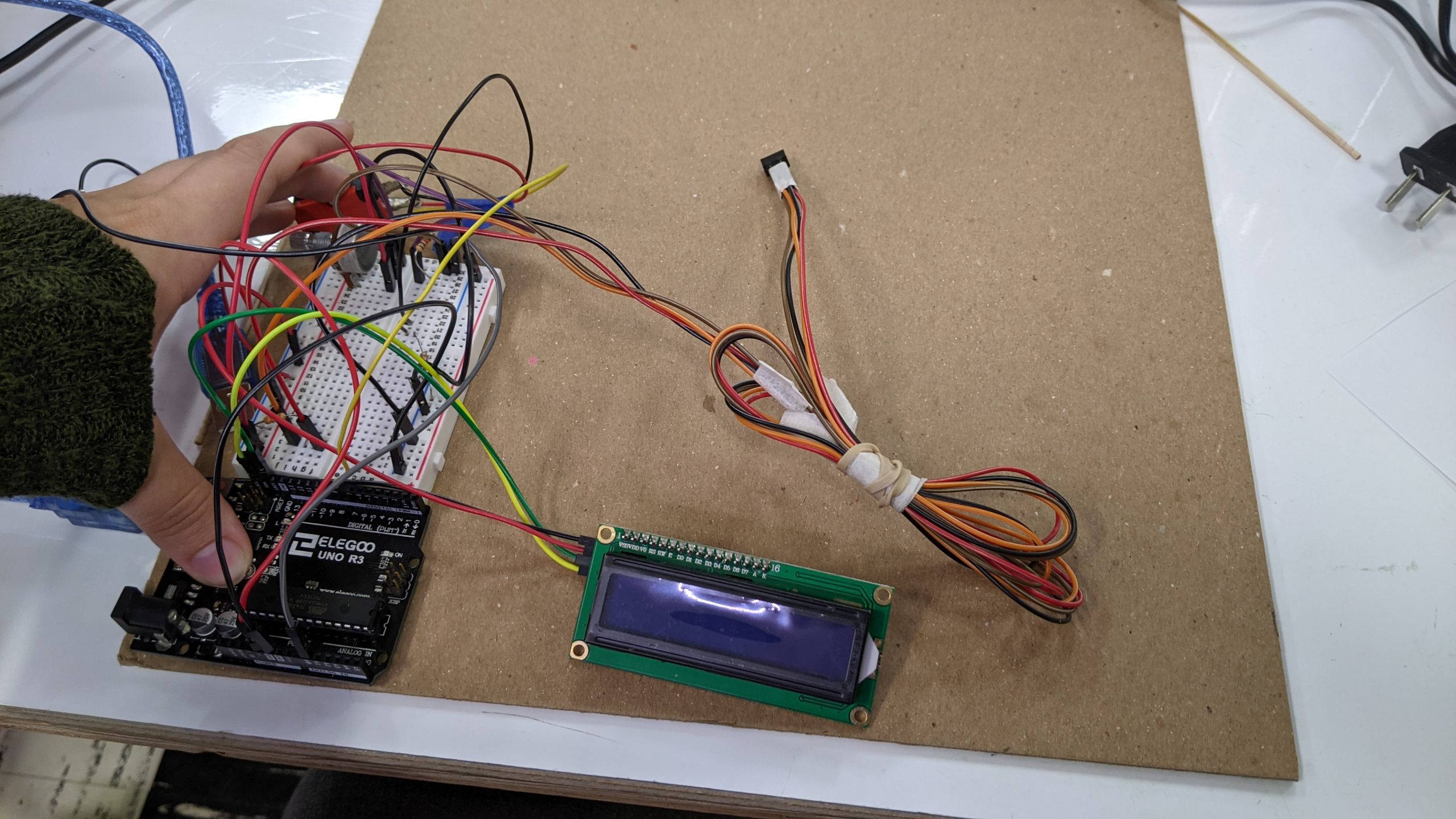
At this stage in the process, the proximity sensor was working and the lever switch was registering the amount of presses in each minute. While each part worked on its own, the parts did not communicate with one another and the refresh rate of the taps was not fast enough to be effective.
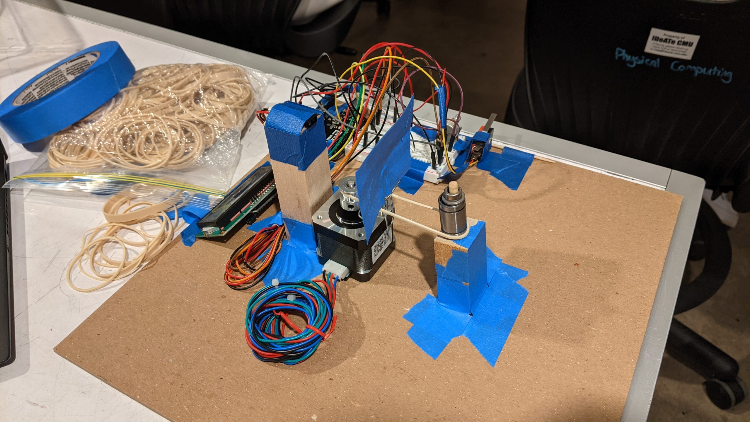
After the stepper motor was in place, it was a bit of a challenge to figure out how to get the mechanism to run smoothly and reliably. Emily had made wooden posts to hold the opposite side, but it took a lot of experimenting with various ball bearings and posts to rotate smoothly while maintaining proper tension. A thin rubber band was also key for not being so strong that it moves the motor or the post.
At this time we were considering changing our design to a change in angle rather than distance as the professor recommended since it would not rely on the mechanics as much. While the deadline was approaching and we still hadn’t actually tested the rubber band belt, thankfully we got the system to work and we decided to go through with our original plan.
Discussion
Although it was frustrating, irksome, and disappointing at times, we’re genuinely grateful for the experience as a whole. When we started, we thought it would be easy to execute our vision since we knew exactly what we wanted. We had everything planned out, so assembling the project should have been fairly straightforward; they weren’t though. Due to our lack of knowledge, experience, and skill, we ran into a lot of unforeseen problems that stumped us for hours at times! An example is when David spent hours revising his code and looking over his wiring to get the stepper motor to work only to have the professor point out that the issue was with the external power supply. There are plenty of examples of simple things holding our progress back, but to name them all would require a book. It’s because of these experiences, however, that we can look back and be thankful; now all of our sorrows become our teachers. We won’t forget semicolons or mix up the wiring for infrared sensors in the future because we’ve already dealt with those mistakes in the past. I think that the lessons we learned will enable us to do a lot more in the upcoming projects. Since our foundation is stronger, we’ll have more creative liberty that will enable us to experiment with things that require more advanced techniques. Overall, the project was a profound learning experience.
One thing we’d do differently in the future is allocate more time toward physically assembling our project. We spent a lot of time getting our individual parts to work (partly because we had to learn how to use them), so we didn’t have much time for integrating everything together. This led to assembly feeling rushed, and some parts looking a bit messy. For example, the paper that is attached to the belt will often fall off if it isn’t handled delicately. If we had made more time to experiment with different mediums and structures, we could have found out what would have worked best for our project, and the assembly process would have been a lot smoother.
Overall, we’re happy with what we’ve accomplished. There are no huge design changes we would make because we got to develop an idea we had from the start and see it through to the end. We’re satisfied because we chose to create something that posed a challenge, but it wasn’t so unfeasible that we had to revert to something less complicated. We executed our idea and made things work, and that feels good.
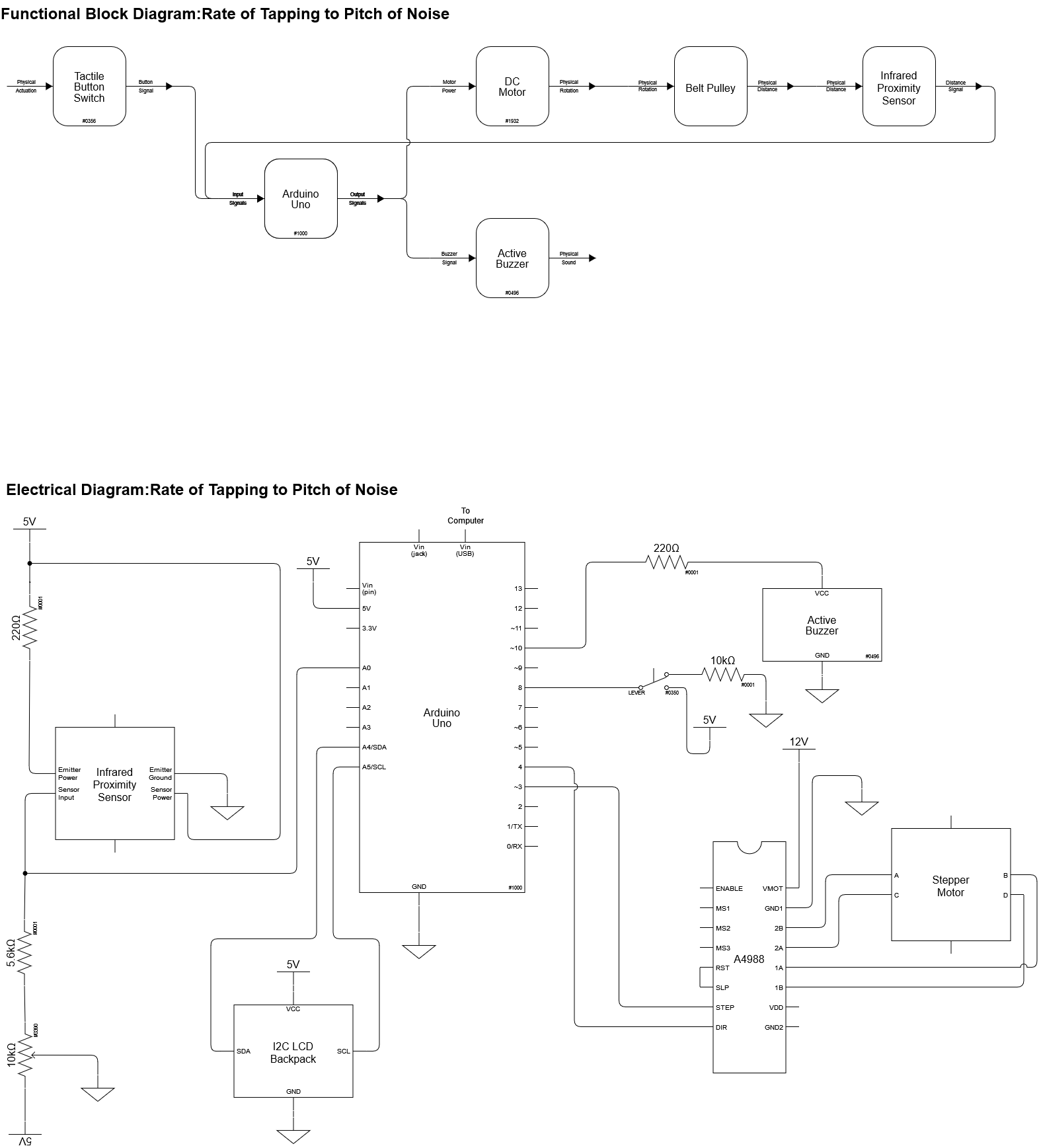
Block Diagram and Schematic
Code
/*
 *  A double transducer: rate of tapping to position to pitch of beeping
 *
 *  Description: This code measures rate of tapping by evaluating the
 *  length of time between taps and translates it to a position value
 *  on a  stepper motor. As the stepper motor moves an index card, an
 *  infrared proximity sensor measures the distance of the card and
 *  sends it back to the Arduino where that value is then mapped to
 *  a value of pitch sent to a speaker.
 *
 * Inputs: Lever switch, Infrared proximity sensor
 *  Arduino pin |  input
 *  8              Lever switch
 *  A0             IR Proximity Sensor
 *
 *  Outputs: Stepper motor direction, stepper motor steps, speaker
 *  Arduino pin |  output
 *  3              Stepper Motor Steps
 *  4              Stepper Motor Direction
 *  10             Speaker
 *
 */

// Additional help and code adapted from:
// https://courses.ideate.cmu.edu/60-223/f2021/tutorials/I2C-lcd
// https://courses.ideate.cmu.edu/60-223/f2021/tutorials/IR-proximity-sensor
// https://courses.ideate.cmu.edu/60-223/f2021/tutorials/button-and-switch
// https://courses.ideate.cmu.edu/60-223/f2021/tutorials/stepper

//INITIALIZATION
#include <Wire.h>
#include <LiquidCrystal_I2C.h>
LiquidCrystal_I2C screen(0x27, 16, 2);

//Pin names
const int CLICKERPIN = 8; //Pin used to record clicker input from tapping
const int STEP_PIN = 3; //Pin used to tell stepper motor how much to move
const int DIR_PIN = 4; //Pin used to tell stepper motor the direction
const int SPEAKER_PIN = 10; //Pin used to tell speaker the pitch
const unsigned long IRPIN = A0; // shortcut to refer to the ir proximeter pin later
unsigned long tap1 = 0; //Records time button was pressed
unsigned long tap2 = 0; //Records last time button was pressed

#include <AccelStepper.h>
AccelStepper myMotor(1, STEP_PIN, DIR_PIN);
int motorPos = 0;

int tapRate = 20; //How many taps per minute
unsigned long timerOne = 0; //Timer for screen refresh rate
int buttonState = 0;

//VOID SETUP
void setup() {
  //Data setup
  Serial.begin(9600);

  //Screen setup
  screen.init();
  screen.backlight();
  myMotor.setMaxSpeed(1000);
  myMotor.setAcceleration(500);

  //Pin Inputs/Outputs
  pinMode(IRPIN, INPUT); // we will be reading the photoresistor pin as an input
  pinMode(CLICKERPIN, INPUT);
  pinMode(SPEAKER_PIN, OUTPUT);
}

//VOID LOOP
void loop() {
  int readVal; // initialize a new integer to store the IR value
  readVal = analogRead(IRPIN); // do the analog read and store the value
  int pitchVal; // initialize a new integer to store the IR value
  pitchVal = map(readVal, 15, 60, 200, 2000); //Mapping the IR distance values to pitch values
  tone (SPEAKER_PIN, pitchVal); //Telling speaker to play a tone at pitch pitchVal

  //Beginning conditional for when neither tap has a value
  if ((digitalRead(CLICKERPIN) == 1) and (tap1 == 0)) {
    tap1 = millis();
    tapRate = (60 / (tap1 * .001));
    if (tap1 <= 1000) {
      tapRate = 60; //Covers boundary conditions, no higher than 60
    }
    if (tap1 >= 3000) {
      tapRate = 20; //Covers boundary conditions, no lower than 20
    }
  }

  if ((digitalRead(CLICKERPIN) == 1) and ((millis() - tap1) > 1000)) {
    tap2 = millis();
    Serial.println((String)"tap1:" + (tap1 * .001) + "s");
    Serial.println((String)"tap2:" + (tap2 * .001) + "s");
    tapRate = (60 / ((tap2 - tap1) * .001));
    if ((tap2 - tap1) <= 1000) {
      tapRate = 60; //Covers boundary conditions, no higher than 60
    }
    if ((tap2 - tap1) >= 3000) {
      tapRate = 20; //Covers boundary conditions, no lower than 20
    }
    motorPos = map(tapRate, 20, 60, 0, 200); //Mapping the tapRate values to position values
    myMotor.moveTo(motorPos);
    Serial.println(motorPos);
    tap1 = tap2;
  }
  myMotor.run();

  if (millis() - timerOne >= 300) { //Refresh rate of screen every 300 milliseconds
    // print the input value onto the screen starting at the above cursor position
    screen.clear();
    screen.home();
    screen.print("i:");
    screen.print(tapRate);
    screen.setCursor(5, 0);
    screen.print("m:");
    screen.print(motorPos);
    screen.setCursor(7, 1);
    screen.print(readVal);
    timerOne = millis();
    screen.setCursor(10, 1);
    screen.print("o:");
    screen.print(pitchVal);
  }
}