Overview
This device reminds a user to not use their phone as frequently by allowing the user to set a timer for how long they’d like to put their phone down for, and if it senses that the phone has been removed before the allotted time is up, the device will flash lights.
Process Images and Review
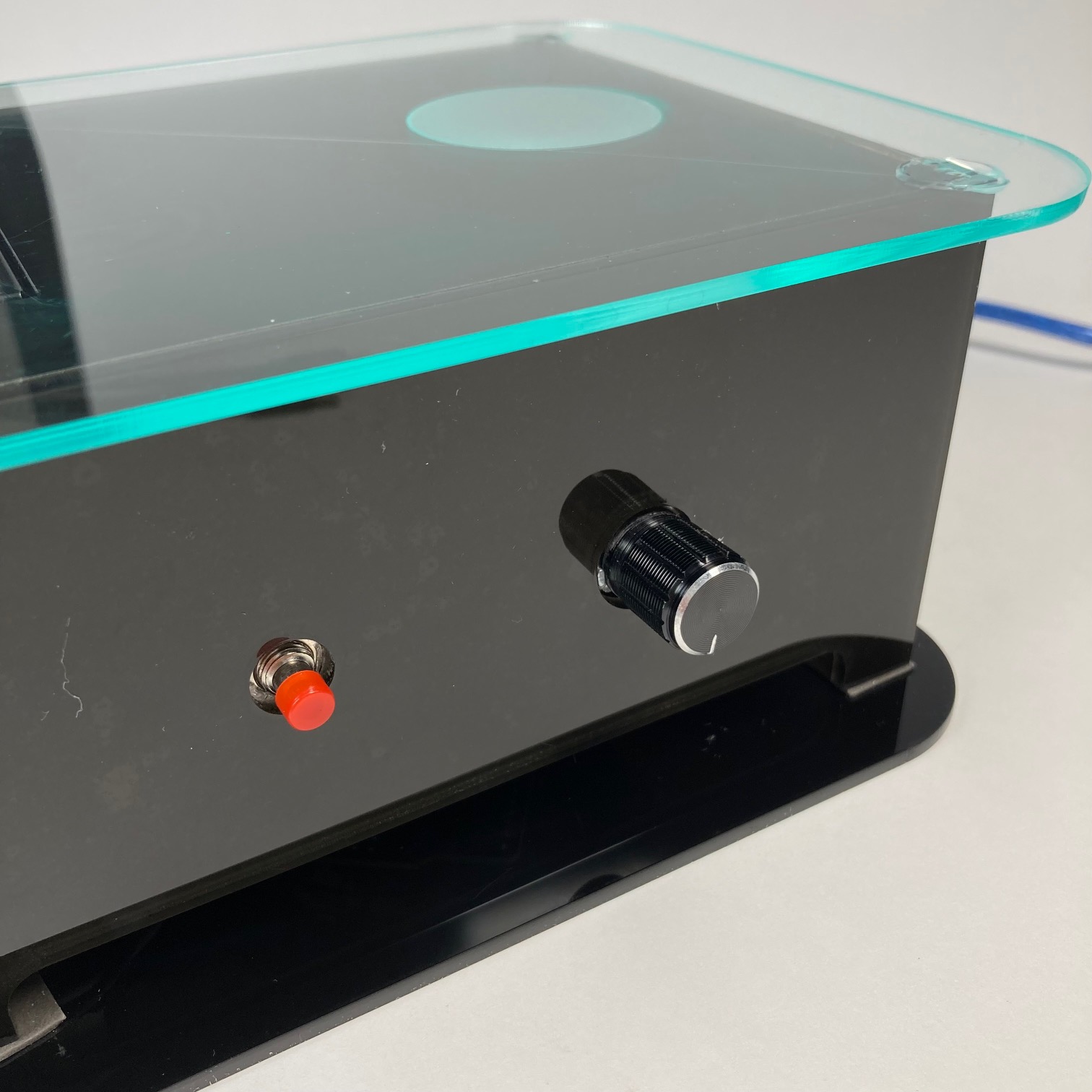
The first decision point I encountered was the selection of what kind of button I wanted to use to set the timer. Initially, I envisioned the button being behind a finger sized acrylic panel on the top of the device which the user could depress, and it would push on a small lever pushbutton to set the timer. Instead, I realized that making the acrylic stay on the lever pushbutton would be pretty difficult given the small surface area on the lever. In prototyping, I used a small black pushbutton as it was the most basic sort of button I could use for testing, and I also considered using the panel to depress the small black pushbutton but that would require sufficient support for the breadboard underneath in order for the user to depress the button safely in the z axis (from on top). Both of these button ideas would require some sort of internal scaffolding within the acrylic box and in the end, there wasn’t enough room and time to design these. Hence, I opted for a red exposed pushbutton for which I laser cut a small opening for on the side of the box with the potentiometer also sticking out. Thus, with both of these components being manipulated directly from the external source (my hand), there was enough cohesiveness to allow both to remain on the side panel of the box.
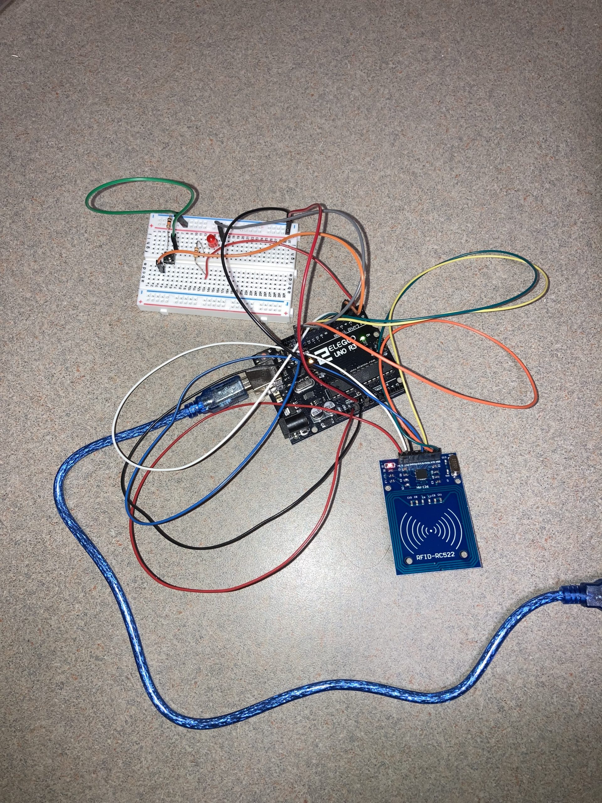
Circuit during the process– originally had a small black pushbutton that I intended on switching out for a lever pushbutton so that I could mount a piece of acrylic on top.
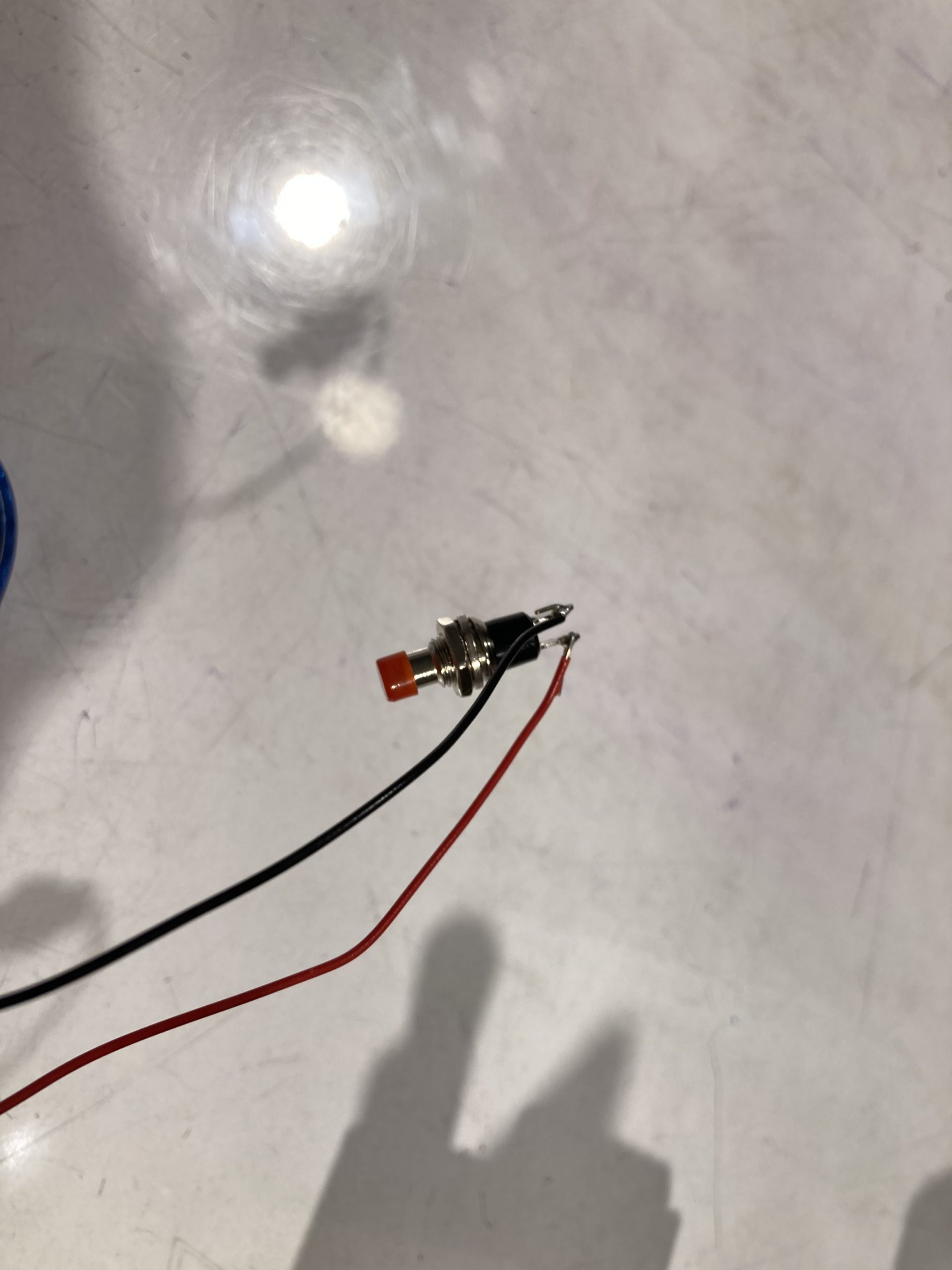
The new pushbutton I selected would peek through the acrylic rather than being hidden.
The second large decision point in my process regarded the alarms that would notify the user that the phone had been removed before the timer went off. In the beginning, I had imagined two sources of alerts– having a light blinking, and also a little buzzer going off. The buzzer would obviously be annoying, but in particular I wanted the blinking of the LED to peek through the smokey black acrylic I intended on using. This would give the effect that the acrylic was glowing and would allow the LED light to pierce through and annoy the user more than it does now. However, after some though while laser cutting, I knew that the smokey acrylic would show all the wiring underneath, which I though would be too exposed and messy. So, I opted to keep the sticky backing of the acrylic intact on one side such that it provided a more opaque wall that would hide the wiring and electronics. Unfortunately, this fix caused the entire box to look very much like it was made of just black acrylic, rather than the sleek, translucent panels I was going for. So I tried to make the most of this by cutting slits along the bottoms of the panels so that you could see the glow of the LEDs when they were on or flashing, in order to sort of emulate a strip of LEDs going across the bottom of the box, akin to my initial sketches. Despite my best efforts, my desire to hide the wiring also hid the light of the LEDs which were already diffused panels and thus not bright enough, so they do not shine through the sticky backing on the acrylic.
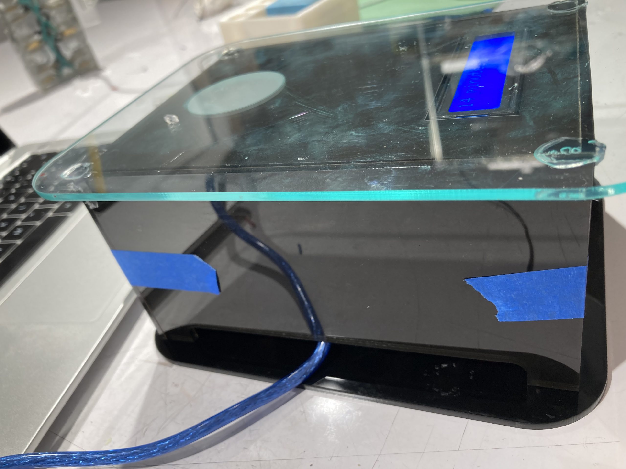
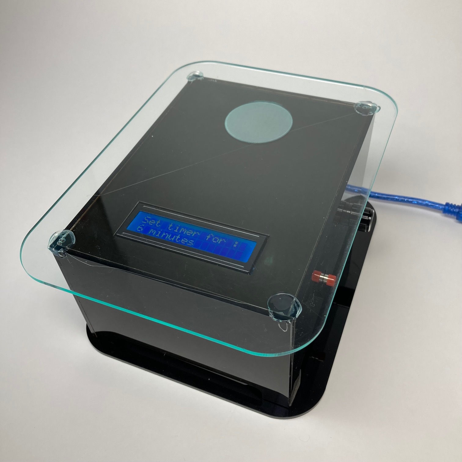
Side of the acrylic box, with panels made of smokey gray acrylic with sticky backing attached, with bottom slits to allow for LED lighting to peek through as much as possible.
Additional Process Images
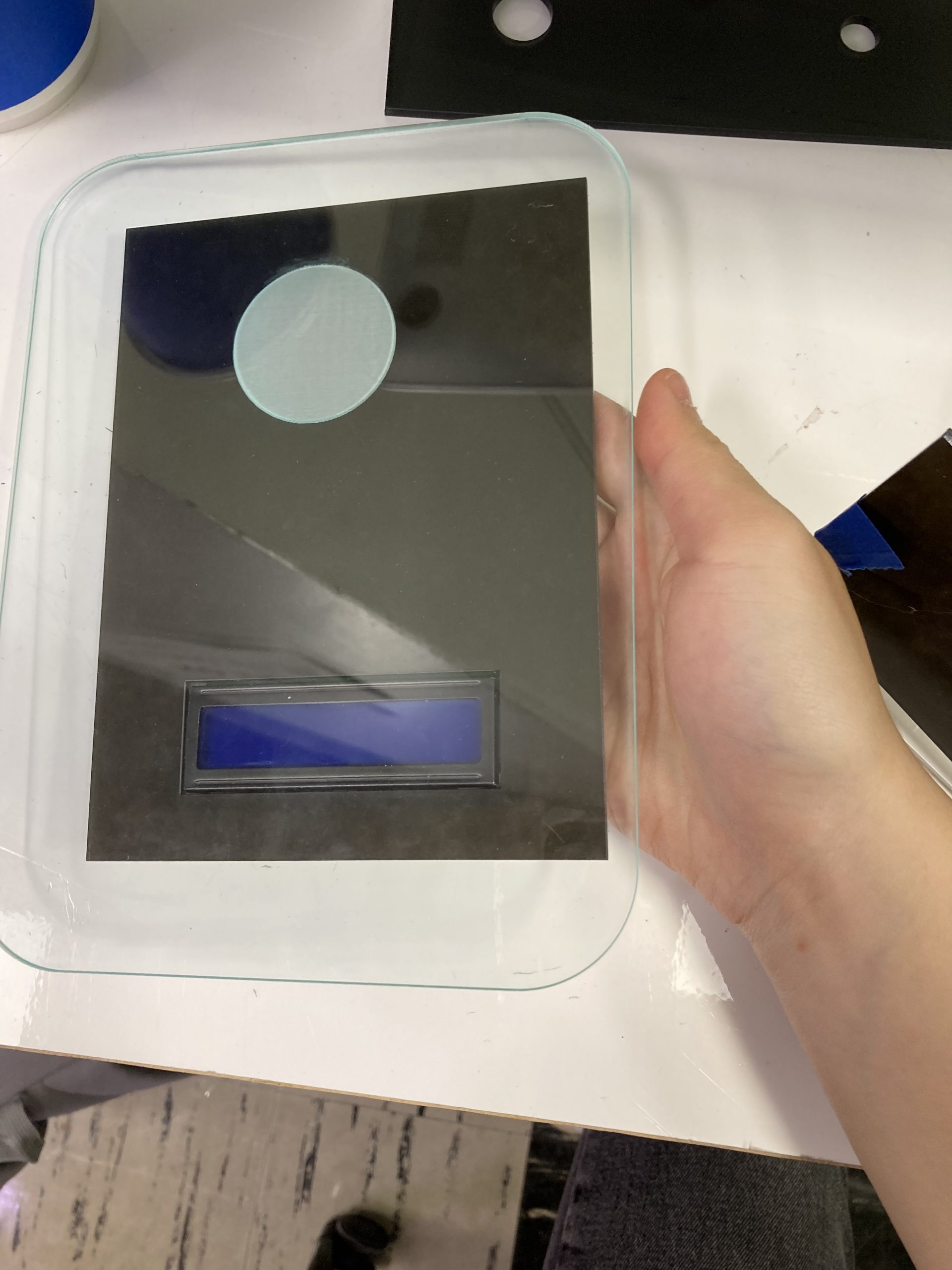
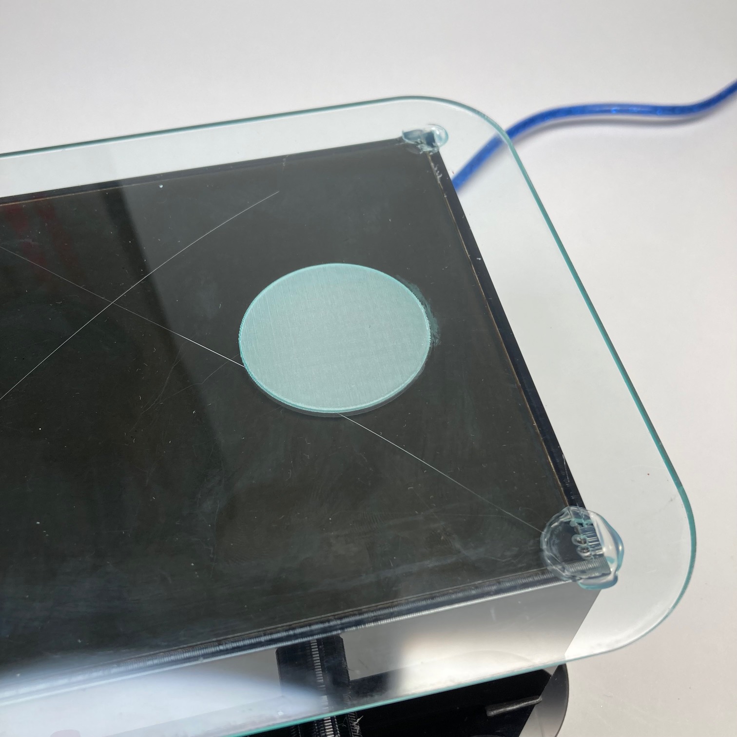
I wanted to make the top as sleek as possible with a plate of green-edged clear acrylic that would cover the LCD display so that it wasn’t exposed. The etched circle indicates where the RFID sensor lies, and faces inwards so that the surface is completely smooth.
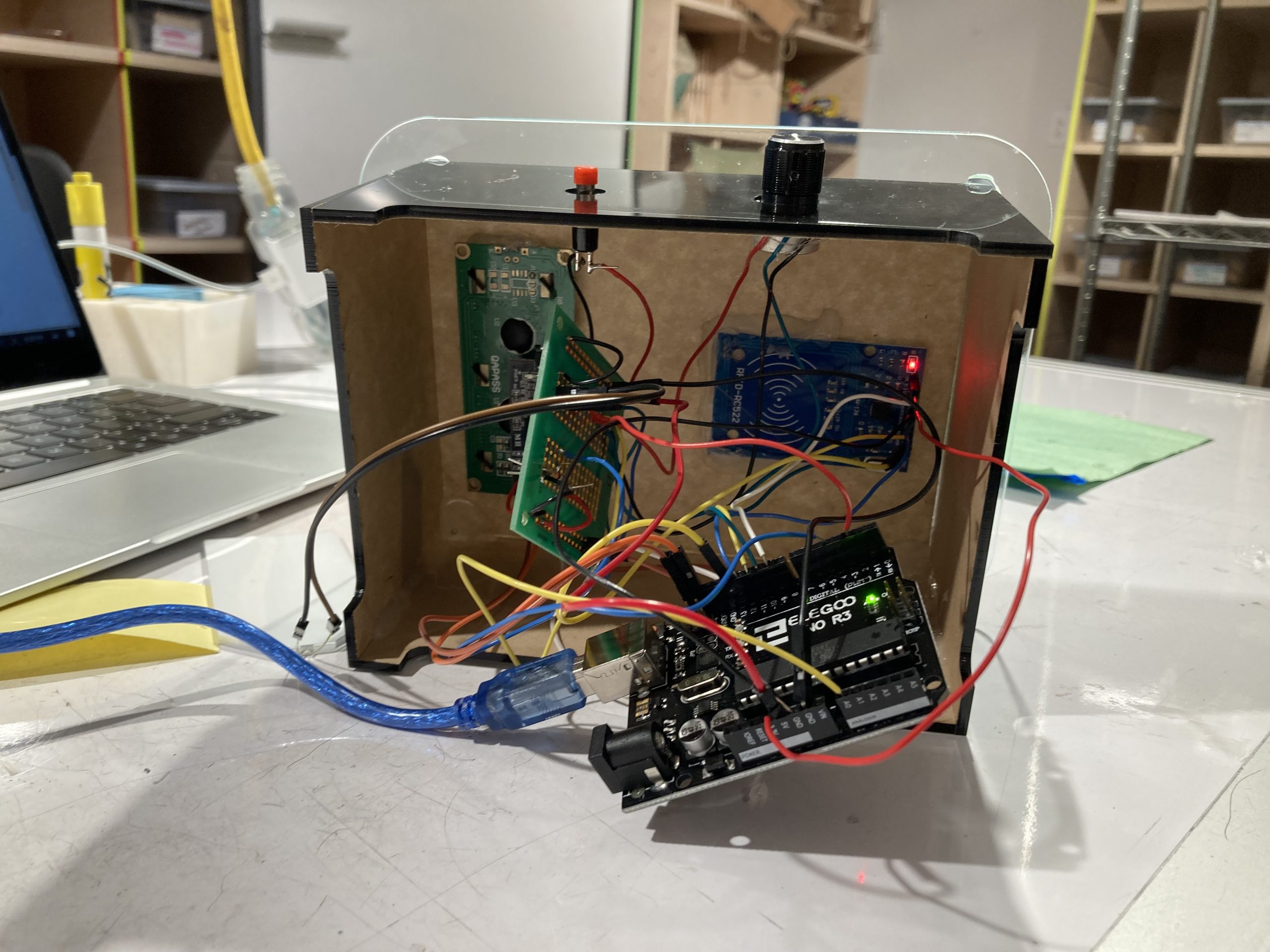
The underside of the device was quite messy. This required me to add an additional bottom panel to add support and structure (seen in second last image).
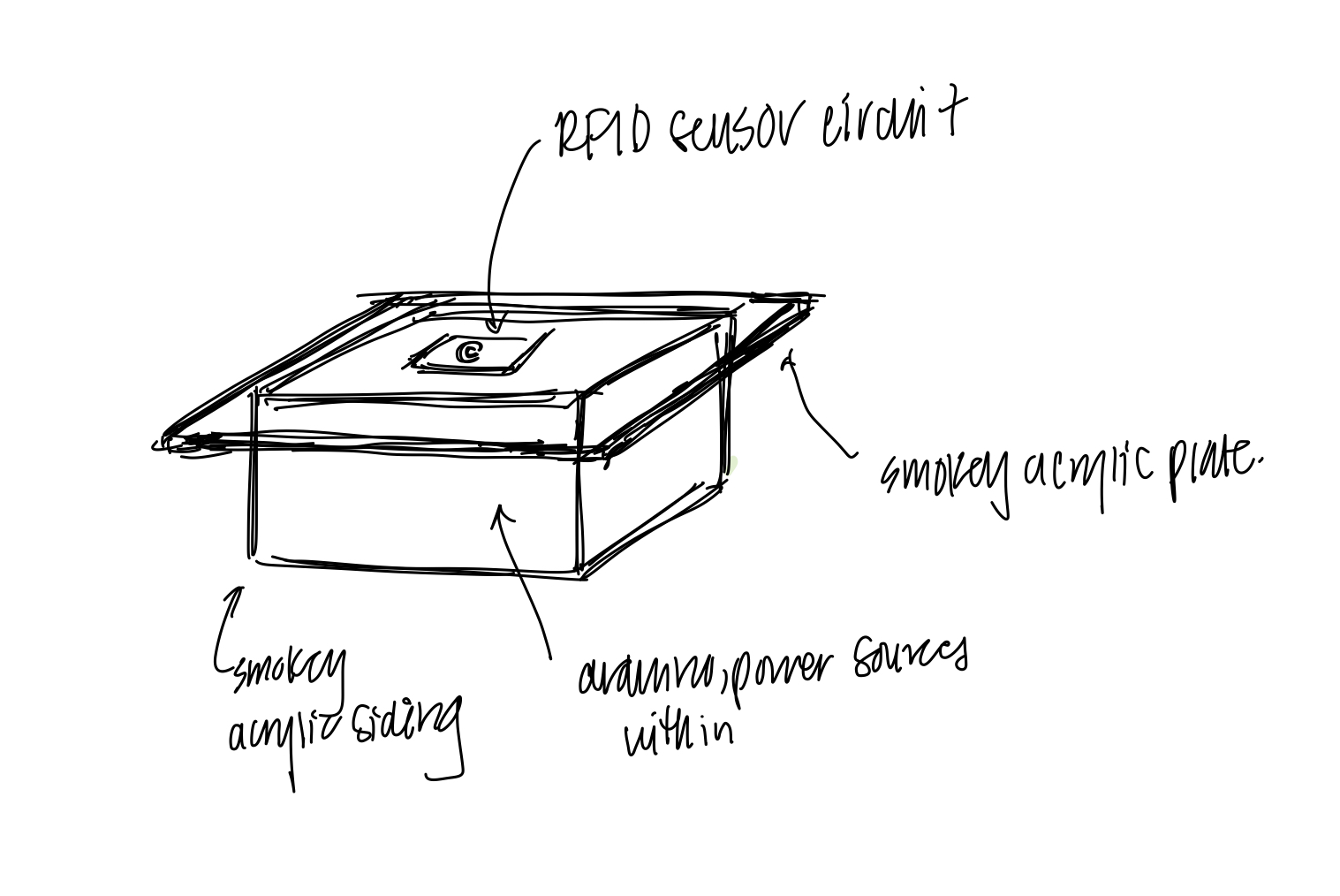
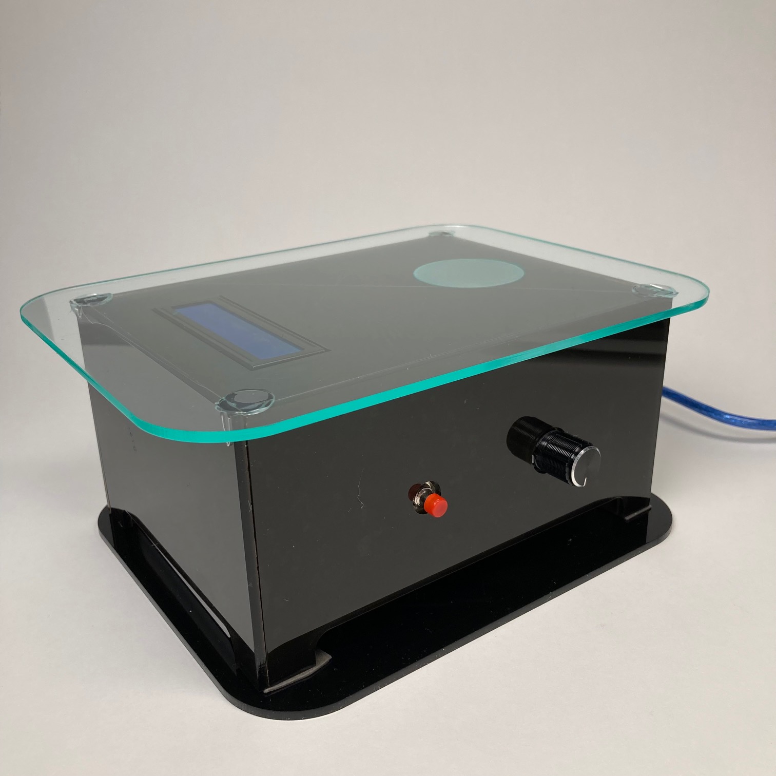
External design with clear acrylic top and smokey grey acrylic sides, with RFID sensor laying underneath top panel.
Discussion
Overall, this project showed me a lot about my own working process as well as allowed me to follow a task from start to finish, all while managing expectations and finding compromises. In the design process, I was very ambitious, putting features that made sense in a design aspect but were not that simple to implement or would be more time consuming to implement. Such is the fallacy of not heeding my own limitations on the time I could spend on this project. During in-class crit, I was granted great criticism from my fellow Paw Paws. Two pieces of criticism I received involved comments on the design:
“I like the etching on the acrylic for where to put your phone! I think that’s a clean solution and the whole thing feels like a scale which fits the interaction of placing your phone down”
“I love the shape and design, but it looks a little big for you to regularly have on your desk”
I agree with both of these sentiments– I tried to make the box as sleek and modernistic as possible with the rounded edges and the etched acrylic for the placement of the RFID sensor. However I also agree that the box became much larger than I intended and more obtrusive that initially planned. If I had scaled the base of the box down a bit and had it be shallower, but still had the acrylic plate on top the same size, it would be a bit more compact for a desk accessory.
Another piece of valuable feedback I received was this:
“I think that it could have a better sort of deterrent system besides LEDs.”
This comment resonates very much– I see this as a major drawback in my project that I wasn’t able to implement more types of deterrents in this device. As I mentioned previously, I intended on having a buzzer be angry at me if the tag was removed before the timer was up, but I wasn’t able to implement this in time. The other IDEATE professor also mentioned this fact, including implementing a more robust system with the LEDs where the flashing rate would increase in intensity as the period of time where the phone was lifted off extended longer and longer, as even more of deterrent. I think these suggestions are ingenious and wish I had thought of them earlier too.
Elaborating on the previous statement, my reflections on this project are mixed. On one hand I like how I was able to use the green-edged clear acrylic and the etched center circle for the RFID placement, as well as how I was able to use a technology that I really like and have learned about– RFID as the foundation of the project as I enjoyed working with it. However, in many ways I did not satisfy all my goals. In my initial planning I listed many features which I was not able to realize, and which would have made this project a more reasonable level of complexity. However I am still reasonably satisfied with how I was able to pull together the basic functionality of the device as I had envisioned it, with the timer and the RFID tag working.
In general, my most relevant reflection is that I learned about my limitations on time management and overcomplicating simple tasks. Firstly, I wasn’t able to put as much time as I had wanted to into the project due to other deadlines. However I think that if I could go back to change things I would definitely continue tinkering with the project more frequently over the weeks rather than doing work large chunks at a time, infrequently. Secondly, I overcomplicated the code, which was one of the first steps I tackled in the project which became a problematic roadblock since I spent so much time on making the code work by adding more and more lines, which just became patchwork to try to make things work off a an ineffective base assumption I made. There was a much simpler solution that I could have seen earlier if I had just taken a step back and though about it a bit, and which would have allowed me to allocate more time towards the design and implementation of more features. I was able to arrive at this solution very late in the process of the project timeline, but since I knew I had to fix the code, I had to factor that time in which limited my ability to work on the hardware.
So, if I were to make another iteration of the project, I would improve on the following points: definitely think critically about the code first and don’t overcomplicate things by continuing to brute force the logic. There’s always an easier way to do things even if that solution isn’t obvious at first. Next, would implement the LED flashing by using NeoPixels as a strip around the bottom of the device as I know that they would be much brighter and I could program them to blink more rapidly as the time the phone was removed in the middle of a timer increased. I would also probably add a buzzer to increase the annoying factor of the deterrent, as it would increase incentive to place the phone back on the plate. Lastly, I would figure out a way to place the RFID tag on the phone in a way such that I could place my phone face down on the top plate, so that I don’t get distracted by the notifications.
Technical Information
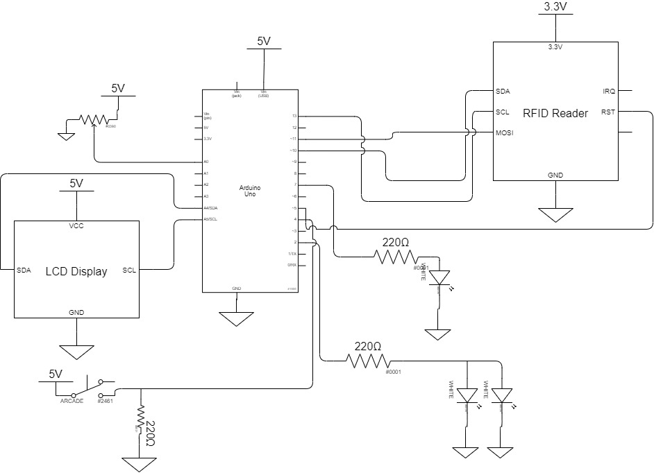
Electronic Schematic
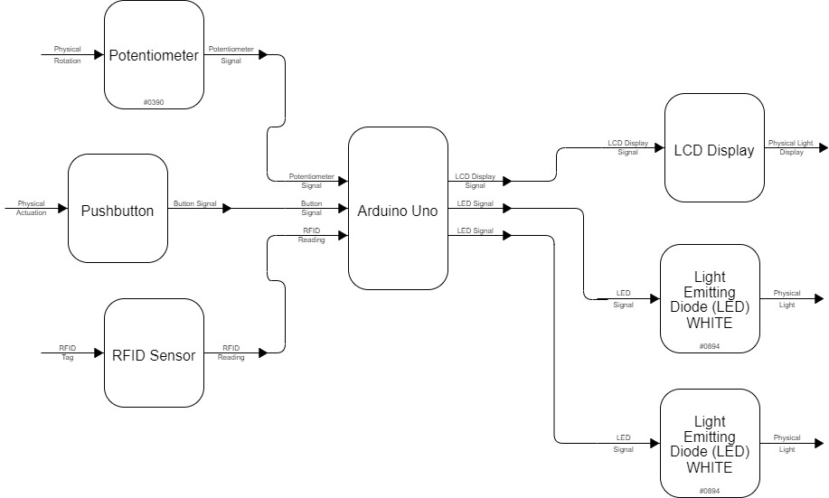
Functional Block Diagram
Code:
/*
* RFID Phone Lock
* Serena Ying 60-223 Fall 2021
* This code utilizes the MFRC522 Library to detect RFID signals from an MFRC522 Reader and
* compatible RFID Tag. The code will detect when an RFID tag is present on the sensor, and
* set a flag to avoid disturbances where the RFID readings do not stay high.
*
* Description:
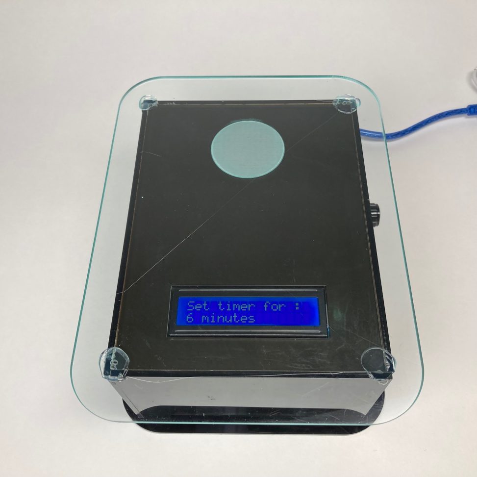
* While the user has not yet set a timer on the device, the LCD Display
* will dynamically show the current value of time which the user can manipulate using the
* potentiometer on the device. Once the user presses the button, this code will save the analog
* reading of the potentiometer signal as the timer value. The LCD display will indicate
* "Phone Down..." to tell the user to place their phone down so that the RFID sensor can be detected,
* which starts the period of phone lock. Then, once the RFID tag has been detected, the LEDs
* will turn on and a counter will begin to count up from 0 to the timer value. The LCD display
* shows a progress bar for how much time out of the timer has elapsed, and indicates "Focus Time...".
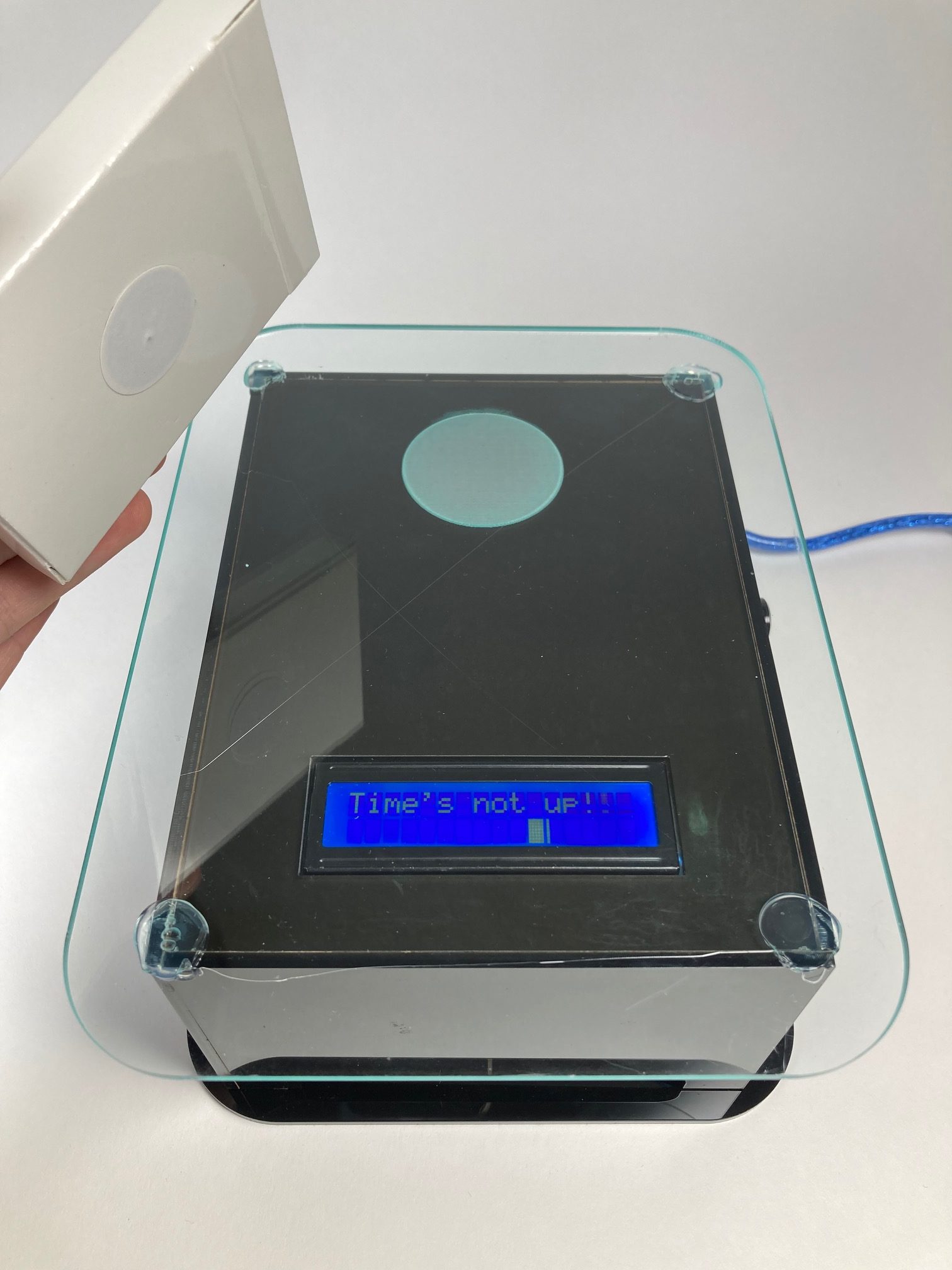
* If the RFID tag is ever not detected on the reader, this code will stop the counter and display
* a LCD message to notify the user that the time is not up yet. In addition, the LEDs will begin flashing.
* Once the RFID tag is once again detected, the LEDs will be constantly on once more and the counter resumes.
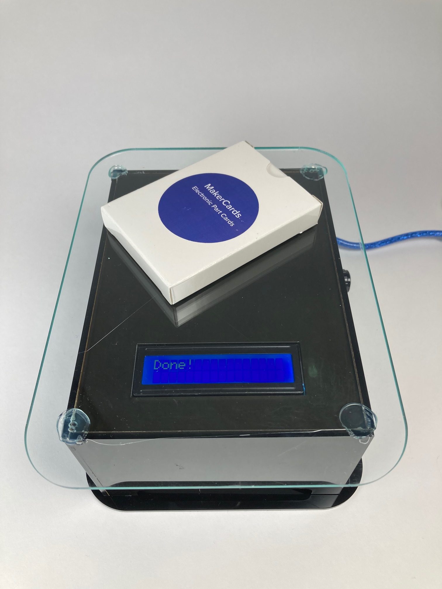
* The LCD display will show "Focus Time..." until the count has reached the timer, at which point it
* displays "Done!" for a short duration before returning to the state in which the user can
* manipulate the potentiometer and read the amount of minutes to set the timer for.
*
* Pin Mapping:
* RFID Pin Arduino Pin
* ---------- -------------
* SDA 10 (input)
* SCL 13 (input)
* MOSI 11 (input)
* MISO 12 (input)
* IRQ --
* GND GND (output)
* RST 5 (output)
* 3.3V 3.3V (ouput)
*
* Signal Arduino Pin
* ---------- -------------
* LED_PIN 2 (output)
* RED_LED 7 (output)
* POT_PIN A0 (input)
* BUTTON_PIN 4 (input)
*
* Credits:
* phenoxyethanol on instructables.com for the Arduino Progress Bar
* lastminuteengineers.com for the RFID starter code
*/
#include <SPI.h>
#include <MFRC522.h>
#include <Wire.h>
#include <LiquidCrystal_I2C.h>
/* Creates an LCD display object called "screen" with I2C address 0x27
which is 16 columns wide and 2 rows tall. */
LiquidCrystal_I2C lcd(0x27, 16, 2);
// RFID Reader pins
#define RST_PIN 9
#define SS_PIN 10
// External Circuit Pins
#define LED_PIN 2
#define RED_PIN 7
#define POT_PIN A0
#define BUTTON_PIN 4
// Consts used for operation of timer loop
const int DELAY_DURATION = 500;
unsigned long time_counter = 0;
unsigned long timer = 0;
unsigned long lcdcounter = 0;
unsigned long ledcounter = 0;
bool ledState = LOW;
int flag = 0;
int shortFlag = 0;
bool done = 0;
int buttonState = 0; // variable for reading the pushbutton status
unsigned long delay_timer = 0;
int runnin = 0; // indicates that the button has been pressed
MFRC522 mfrc522(SS_PIN, RST_PIN); // Create MFRC522 instance
// Arrays for progress bar display
byte zero[] = {
B00000,
B00000,
B00000,
B00000,
B00000,
B00000,
B00000,
B00000
};
byte one[] = {
B10000,
B10000,
B10000,
B10000,
B10000,
B10000,
B10000,
B10000
};
byte two[] = {
B11000,
B11000,
B11000,
B11000,
B11000,
B11000,
B11000,
B11000
};
byte three[] = {
B11100,
B11100,
B11100,
B11100,
B11100,
B11100,
B11100,
B11100
};
byte four[] = {
B11110,
B11110,
B11110,
B11110,
B11110,
B11110,
B11110,
B11110
};
byte five[] = {
B11111,
B11111,
B11111,
B11111,
B11111,
B11111,
B11111,
B11111
};
// Print formatter helper function used for debugging
void formatPrint( char *leftStr, unsigned long MyVar1, char *sepStr, unsigned long MyVar2, char *rightStr, unsigned long MyVar3) {
Serial.print (leftStr);
Serial.print (MyVar1);
Serial.print (sepStr);
Serial.print (MyVar2);
Serial.print (rightStr);
Serial.println (MyVar3);
}
// Setting up RFID reader, button, LEDs, and potentiometer
void setup() {
Serial.begin(9600); // Initialize serial communications with the PC
SPI.begin(); // Init SPI bus
mfrc522.PCD_Init(); // Init MFRC522
delay(4); // Optional delay. Some board do need more time after init to be ready, see Readme
mfrc522.PCD_DumpVersionToSerial(); // Show details of PCD - MFRC522 Card Reader details
pinMode(LED_PIN, OUTPUT);
pinMode(RED_PIN, OUTPUT);
pinMode(BUTTON_PIN, INPUT);
pinMode(POT_PIN, INPUT);
// for setting up the lcd:
lcd.init();
lcd.backlight();
lcd.home();
lcd.createChar(0, zero);
lcd.createChar(1, one);
lcd.createChar(2, two);
lcd.createChar(3, three);
lcd.createChar(4, four);
lcd.createChar(5, five);
}
// Function to update progress bar as the count increases until the set timer, causes lcd to animate blocks going across the screen
void updateProgressBar(unsigned long count, unsigned long totalCount, int lineToPrintOn) {
double factor = totalCount / 80.0;
int percent = (count + 1) / factor;
int number = percent / 5;
int remainder = percent % 5;
if (number > 0)
{
lcd.setCursor(number - 1, lineToPrintOn);
lcd.write(5);
}
lcd.setCursor(number, lineToPrintOn);
lcd.write(remainder);
}
// Main loop for operation, waits for button press to begin the counter and other functionality
void loop() {
// for lcd:
if (millis() - lcdcounter >= 500) {
lcd.clear();
lcd.home();
lcd.print("Set timer for :");
lcd.setCursor(0,1);
lcd.print(timer);
lcd.print(" minutes");
lcdcounter = millis();
}
// check button, if pressed, stop updating the timer to pot_pin (sets the timer) and resets counter to 0, done to 0, and
// updates runnin to 1
buttonState = digitalRead(BUTTON_PIN);
if (buttonState == HIGH) {
Serial.println("BUTTON PRESSED");
runnin = 1;
done = 0;
time_counter = 0;
}
else if (buttonState == LOW) {
timer = map(analogRead(POT_PIN), 0, 1023, 60, 0);
Serial.println(timer);
}
// Runnin indicates that the button has been pressed and that the next thing to check for is the RFID tag state
while (runnin) {
buttonState = digitalRead(BUTTON_PIN);
if (buttonState == HIGH) {
Serial.println("BUTTON PRESSED");
digitalWrite(LED_PIN, LOW);
Serial.println("DONE!");
if (millis() - lcdcounter >= 500) {
lcd.clear();
lcd.home();
lcd.print("Are you sure???");
delay(3000);
done = 0;
lcdcounter = millis();
runnin = 0;
return;
}
}
// for lcd to print out three options of messages
if (millis() - lcdcounter >= 500) {
lcd.clear();
lcd.home();
if (time_counter == 0) {
lcd.print("Phone Down...");
}
else if (shortFlag) {
lcd.print("Time's not up!!");
}
else {
lcd.print("Focus Time...");
}
updateProgressBar(time_counter, timer, 1);
lcdcounter = millis();
}
// if time has been reached, we can exit
if (time_counter >= timer) {
done = 1;
Serial.println("Done!");
}
// if time has not been reached, enter the operation function which maintains the counter on a delay loop
if ((millis() - delay_timer) >= DELAY_DURATION) {
operation();
delay_timer = millis();
}
// if we have indicated that the RFID tag has been removed prematurely, set the shortFlag and blink the LED
if (shortFlag) {
if (millis() - ledcounter >= 500) {
ledState = !ledState;
ledcounter = millis();
}
digitalWrite(LED_PIN, ledState);
digitalWrite(RED_PIN, ledState);
}
// if the done flag has been set from within the operation function, turn off the LED and update the LCD display
if (done) {
digitalWrite(LED_PIN, LOW);
Serial.println("DONE!");
if (millis() - lcdcounter >= 500) {
lcd.clear();
lcd.home();
lcd.print("Done!");
delay(3000);
done = 0;
lcdcounter = millis();
runnin = 0;
return;
}
}
}
}
// Operation function begins once the button has been pressed, which set the timer, and sets flags which indicate if the
// tag is present or not
void operation() {
if (!done) {
flag = 0;
if (mfrc522.PICC_IsNewCardPresent())
{
flag = 1; // card present
}
else //try again to catch the toggle effect
{
if (mfrc522.PICC_IsNewCardPresent()) flag = 1; // card present
}
// if present, increment the counter
if (flag) {
Serial.println("Flag!");
time_counter = time_counter + 1;
Serial.println("Timecounter:");
Serial.println(time_counter);
digitalWrite(LED_PIN, HIGH);
digitalWrite(RED_PIN, LOW);
if (shortFlag) {
shortFlag = 0;
Serial.println("Resetting shortFlag");
}
}
// if not present, do not increment the counter and check if the time is premature or not
else {
Serial.println("No Flag!");
Serial.println(time_counter);
if (time_counter != 0 && time_counter < timer) {
Serial.println("Nope");
shortFlag = 1;
}
}
}
}