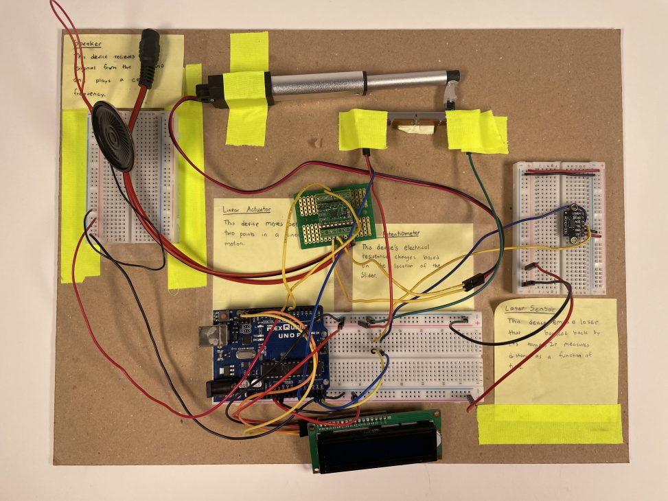
Ethan’s final double transducer
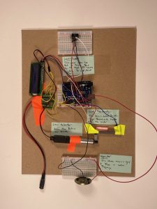
Harry’s final double transducer
Process Images:
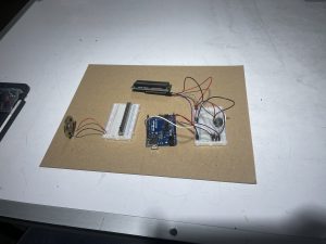
Our initial layout (Harry)
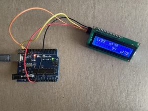
The LCD screen working (Ethan)
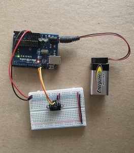
VL53L0X Laser Sensor working (Ethan)
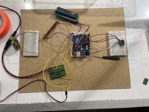
Starting to connect each step together (Harry)
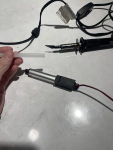
Preparing to shave the hot glue stick (Harry)
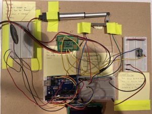
Every step wired up together (Ethan)
Detail Photos:
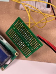
Beautiful soldering job by Harry
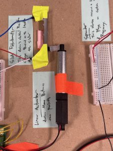
The linear actuator is attached to slide potentiometer with a stick of hot glue
Double Transducer in Action:
Narrative Description:
When an object moves within one to four inches of the laser distance sensor, the linear actuator will either push or pull along the slide potentiometer. Based on the location of the slide potentiometer knob, a respective pitch is played.
Discussion:
We initially struggled with connecting the linear actuator with the other components of the project board. We were successfully able to devise a method to create a temporary connection between the knob of the slide potentiometer and the linear actuator using a slightly melted stick of hot glue. Once we had this connection it was very easy to incorporate the linear actuator with the project board — we simply just masking tape. However, this was only the beginning of our troubles with the linear actuator. Due to the nature of our double transducer, we wanted to be able to control the position of the linear actuator. Unfortunately, there were only two default motions — extend and retract. Luckily, we were cleverly able to implement a type of feedback control. Otherwise, we were going to need to scrape our entire middle step.
There were technically components of this project that came easily to the both of us due to previous experience. For example, soldering the connections for the middle step and breadboard management were both emphasized in our previous coursework. Looking towards the future, a few areas of improvement are wire management and reducing the number of loops. If we were able to implement our double transducer more minimally, it would increase the quality of the project board.
Throughout the project timeline, we need to make important decisions regarding how the double transducer was going to be designed. One noticeable example is how we decided to replace the ultrasonic ranger with a VL53L0X laser distance sensor. This decision was overall made because we desired a more accurate measurement for our middle step. On the software-side, we needed to make decisions regarding how each signal would behave with each other. For example, we had the resistance value of the slide potentiometer relate directly to the pitch of the speaker. This decision was born out of the desire of a more direct relationship between the potentiometer and the pitch.
Block Diagram:
Electric Schematic:
Code:
/*
* @Project Title: Double Trasducer: Height to Pitch
*
* @Authors: Harry Schneider & Ethan Lu
*
* @Description:
* - Using a VL53L0X Laser Sensor to measure the height
* of an index card (1''- 4'').
*
* - The measured height determines how far the linear
* actuator moves, which drags the knob of the slide
* potentiometer.
*
* - The Ardunio maps the potentiometer signal to [200, 2000]
* and sends a frequency to be played by the speaker.
*
* @Mapping:
* Arduino pin | role | description
* ------------|--------|-------------
* A0 INPUT Potentiometer Signal
* A4 INPUT VL53L0X SDA
* A5 INPUT VL53L0X SCL
* SCD INPUT LCD SDA
* SCL INPUT LCD SCL
* 7 OUTPUT Linear Actuator INPUT
* 8 OUTPUT Linear Actuator INPUT
* 9 OUTPUT Speaker Signal
*/


/* import header files */
#include <Wire.h>
#include <LiquidCrystal_I2C.h>
#include <VL53L0X.h>

/* object declaration */
VL53L0X sensor;
LiquidCrystal_I2C screen(0x27, 16, 2);

/* pin-related variables */
const int res_pin = A0;
const int laser_SDA = A4;
const int laser_SCL = A5;
const int act_out1 = 7;
const int act_out2 = 8;
const int pitch_out = 9;

unsigned long prev_distance = 0;

/* VL530X-related varaibles*/
unsigned long lcd_timer;
unsigned long count = 0;

/* unfiltered sensor variables */
unsigned distance_val;
unsigned pot_val;
unsigned pitch_val;

/* filtered sensor variables */
unsigned adjusted_distance_val;
unsigned adjusted_pot_val;

void setup() {
  Wire.begin();

  /* pin setup */
  pinMode(res_pin, INPUT);
  pinMode(laser_SDA, INPUT);
  pinMode(laser_SCL, INPUT);

  pinMode(act_out1, OUTPUT);
  pinMode(act_out2, OUTPUT);
  pinMode(pitch_out, OUTPUT);

  /* VL53L0X Sensor */
  sensor.init();
  sensor.setTimeout(500);
  sensor.startContinuous();

  /* I2C display */
  screen.init();
  screen.backlight();
  screen.home();
}

/* sends out the linear actuator */
void extend() {
  digitalWrite(act_out1, LOW);
  digitalWrite(act_out2, HIGH);
}

/* returns the linear actuator */
void retract() {
  digitalWrite(act_out1, HIGH);
  digitalWrite(act_out2, LOW);
}

void loop() {
  distance_val = sensor.readRangeContinuousMillimeters();

  if (distance_val < 154) {
    pot_val = analogRead(res_pin);
    pitch_val = map(pot_val, 0, 918, 200, 2000);

    /* send signal to speaker */
    tone(pitch_out, pitch_val);

    if (prev_distance < distance_val) {
      extend();
    }
    else if (distance_val < prev_distance) {
      retract();
    }

    /* status display */
    if (250 <= millis() - lcd_timer) {
      /* safety clear */
      if (count % 2 == 0){
        screen.clear();
      }

      adjusted_distance_val = map(distance_val, 52, 154, 0, 99);
      adjusted_pot_val = map(pot_val, 0, 1050, 0, 99);

      /* update LCD screen*/
      screen.setCursor(0, 0);
      screen.print("i:" + String(adjusted_distance_val));

      screen.setCursor(6, 0);
      screen.print("m:" + String(adjusted_distance_val));

      screen.setCursor(8, 1);
      screen.print(String(adjusted_pot_val));

      screen.setCursor(12, 1);
      screen.print("o:" + String(pitch_val));


      screen.home();
      lcd_timer = millis();
      count++;
    }

    prev_distance = distance_val;
  }
  else {
    /* safety clear */
    if (count % 2 == 0){
        screen.clear();
    }

    /* return to base LCD screen */
    screen.setCursor(0, 0);
    screen.print("i:" + String(99));

    screen.setCursor(6, 0);
    screen.print("m:" + String(99));

    screen.setCursor(8, 1);
    screen.print(String(99));

    screen.setCursor(12, 1);
    screen.print("o:" + String(99));
    noTone(9);

    count++;
  }
}
