Project 2: An assistive device for someone you know very well
due at the beginning of class on Monday, Mar. 5th
This class’s overall project is to build assistive devices for older people which can be helpful to them in their lives.
Your assignment is to make an assistive device for yourself. It should actually function in its intended role and be something that makes some task, practice, or aspect of your daily life easier, simpler, more comfortable, or in some meaningful way better for you; however, it is perfectly acceptable for the device to be something that is more fanciful and less practical. While your device may have major mechanical components, you are expected to build in at least some electronic logic as well using the Arduino or another microcontroller.
The meaning of an assistive device
The traditional notion is that “assistive devices” are things that look like this:
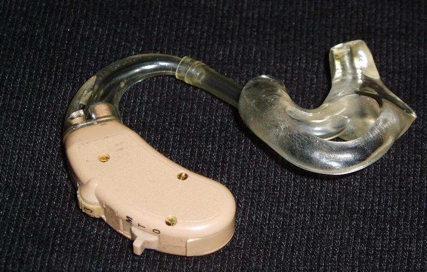 (image from Udo Schröter via Wikimedia Commons)
People often think of assistive devices as things that are used exclusively by people with physical disabilities. In fact, the top of the Wikipedia entry for “Assistive technology” reads “Assistive technology is an umbrella term that includes assistive, adaptive, and rehabilitative devices for people with disabilities and also includes the process used in selecting, locating, and using them.” (Emphasis mine.)
Artist / educator / deep thinker Sara Hendren, in an essay entitled All Techology is Assistive, responds to this sort of thinking:
Instead of labeling some technologies and not others as assistive, let’s start like this: We’re all getting all kinds of help from the things we make. All kinds of help, all the time, for our many material and social and educational and political needs. Private needs and public ones. No one is exempt.
An assistive device, for our purposes, is fundamentally any piece of technology which makes any task or practice easier for any person. A cane is an assistive device: it helps somebody walk more easily. A pair of reading glasses is an assistive device: it helps someone read. A bicycle is an assistive device: it helps someone move quickly from one place to another.
There are a huge variety of creative and interesting assistive devices which look very little like the classic pink-plastic device shown above, and which serve all sorts of purposes.
Some examples
Noted researcher Temple Grandin worked with Prof. Wendy Jacob to produce “squeeze chairs”: pieces of furniture with inflatable elements designed to provide deep pressure, a sensation which is known to significantly calm and comfort some people on the autistic spectrum:
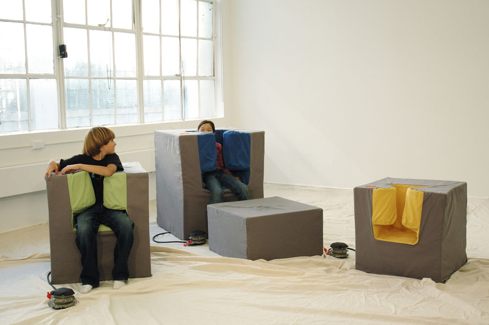 (Squeeze Chair image from Sara Hendren’s Abler blog)
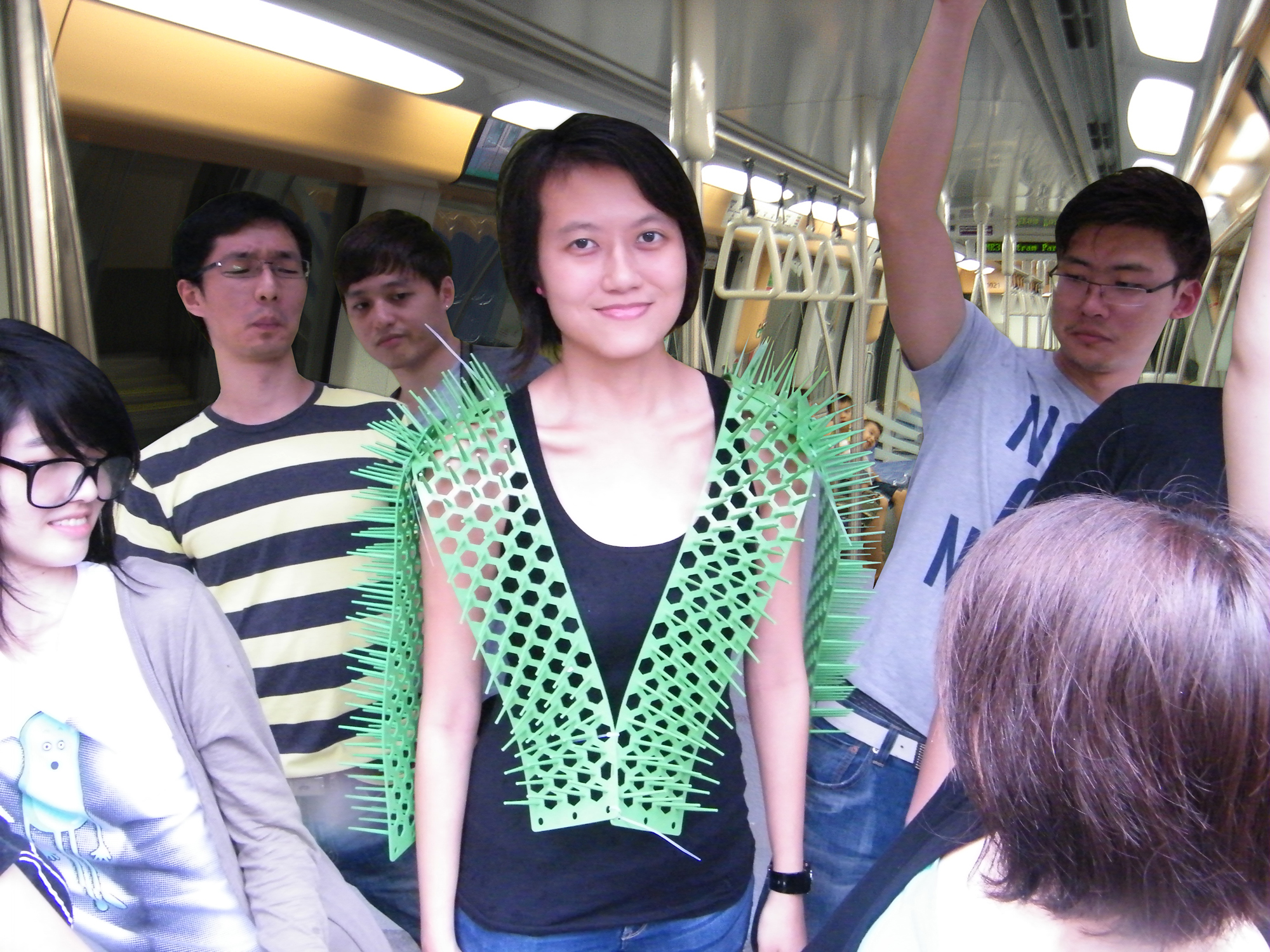
Industrial designer Siew Ming Cheng wanted the people near her on the subway to maintain a healthy distance, so she built “Spike Away” in a two-day workshop:
CMU design student Mackenzie Cherban made a really strong project to help her grandmother, who has limited hearing, know when her cell phone is ringing from the next room over. It consists of a photosensor positioned to face into the screen of a smart device (phone, tablet, etc.). An Arduino reads the photosensor’s values, and when it detects a light level over a certain threshold, it triggers two large bright LEDs on a breadboard to blink. The idea is that these indicator lights could be the next room over from the phone/tablet, and alert the user to the fact that the phone has a notification.
In 2009, a woman named Cindy had a major heart attack, and in the course of her hospitalization had a strong reaction to a drug she was given and nearly died. She survived, but owing to complications she had to have at least some amputation done somewhere on all four of her limbs. Waking up from the ordeal after a coma, she was living in a body that was profoundly changed.
Sara Hendren (mentioned above) and her colleague Caitryn Lynch found out about Cindy and the ingenious range of adaptations and assistive devices she uses, and they built a website that explores them in some depth called Engineering at Home. In many cases, Cindy repurposed an existing tool to suit her own needs, while in other cases, the tools were built specifically for her.
Long a fan of handwritten correspondence, Cindy had lost the ability to hold a pen in her right hand until her prosthetist built her a silicone boot to put at the end of her arm, with a hole in it for the pen to go through:
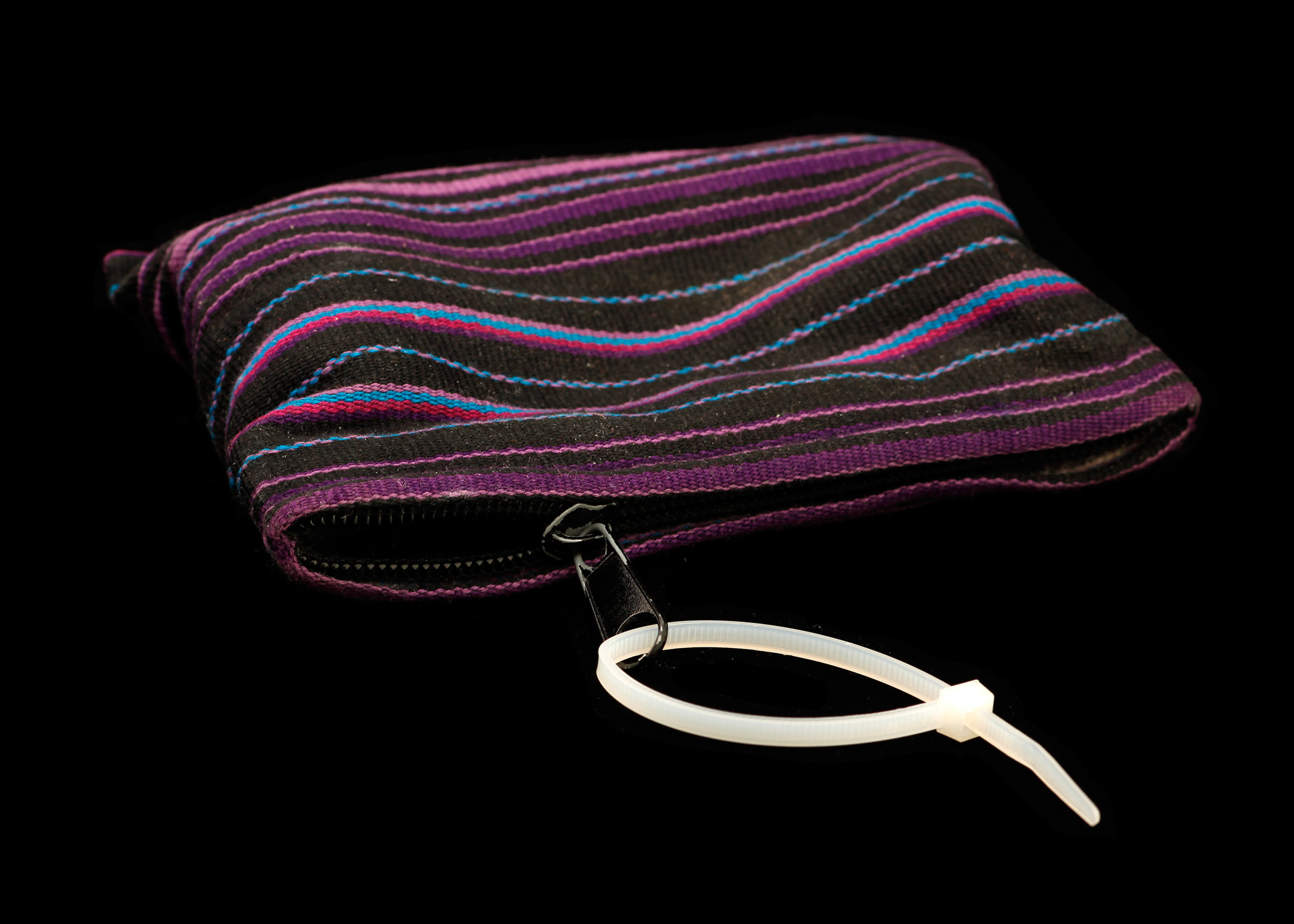
Many of the adaptations are decidedly low tech. Cindy says she has “hundreds” of cable ties, which make it easier for her to grip all sorts of things, such as zipper pulls:
Often, Cindy is able to use an existing tool for a purpose other than what is typical. For instance, she uses cooking tongs to hold a sandwich so she can easily pick it up and put it down while eating, just like everyone else at the table is:

All of these disparate examples are meant to show that 1) “assistive technology” is actually a very broad category, 2) low-tech answers can be very good answers, and 3) the potential range of inventive ideas to address various problems is enormous.
(One note on #2 above is that this project assignment requires that you build some electronic logic of some sort into your assistive device. But perhaps you will not need to begin with the electronics, which may, for instance, provide additional useful affordances to a device that is primarily physical.)
Begin by brainstorming
Begin by taking note of your daily life, trying to use a critical eye on yourself as much as you’re able. Are there any tasks that you regularly do that are difficult or frustrating for you? Are there things that are difficult to reach; do you fall asleep in an uncomfortable pose; do you wish you would do a better job of brushing your teeth or talking with strangers on the bus or washing your hands regularly? Do you have discomfort in your body that some well-designed tool could help with? Are there important things you forget regularly?
Look at your life with a critical eye over the next couple of days, make a note of things that are in any way difficult for you, and sketch out at least three (very sketchy) ideas to bring in to discuss briefly in class on Monday 2/19.
Building a simple physical mockup
Once you have some idea of the thing you want to build, you may want to investigate a space-filling mockup. Keep it simple; throwing something together with cardboard and hot glue is a great way to get some ideas about what your assistive device could look like. Does it fit into a pocket? Or a small pouch? Do you need an enormous cart to move it around the world? If you could idealize it into any form, what would that be? (If there’s one thing we know about electronics, it’s that there are ways to make them quite small; there may be miniaturization techniques applicable to your project.)
Building the final physical embodiment of your device
Building hardware is often far more challenging than meets the eye! As soon as you want to depart at all from something as simple as a lasercut wooden box, you will find that building satisfactory forms—especially if they have any moving parts whatsoever—is often a very complex undertaking. Depending on your particulars, this may be the most difficult part of the project to scope effectively. The best advice here is very general: start early with some sketches of what you want to make; move from sketches to some sort of fabrication; and try to guard against spending too many hours quibbling about very fine details.
Building an electronic mockup
If you are at a point where you’re ready to begin to prototype electronic logic, then by all means, dust off the breadboards and whatever components you’ll need, and throw something together. We are at a point in the course where you should feel comfortable with the software and electronics you’ll need to get started, and the first step is to just jump right in.
Once you’ve begun, you may identify a particular challenge—for instance, you find some complex software timing issue you don’t know how to solve, or you will need to use an electronic component that is new to you. These are the sorts of questions that Joseph and Zach are happy to help with during office hours or via email. But the only way to identify these sticking points is to get to the point that you actually encounter them, which is why building a simple mockup early is a good idea.
Feedback allocations
Documentation is worth 65% of the grade for this project, and a good portion of the documentation grade consists of images and discussion of your steps and missteps along the way. Documentation will be due after the project critique on Monday, March 5th, but it’s not possible to take meaningful progress images at any time other than while you’re actually progressing! For that reason, it’s critical that you take pictures as you’re going. Pictures of your mess of components on the table—pictures of any experimental models you try, which may work or may fail—screenshots of expected or unexpected Serial feedback during your testing—pictures of anything along the way that will help you explain your process. Take lots of pictures as you go!
The demonstration for this project requires that you make something that works; demonstrating its actual functioning at the crit will be a portion of your grade. (Partial credit may be given if it is only partially working.)
Credit is allocated as follows:
- 65% documentation
- 30% images
- 25% writing sections
- 5% schematic
- 5% code
- 15% concept: the idea is good, original, and ostensibly useful to the creator
- 20% execution: technical performance (judged at the final crit)
- 10% input works reliably as intended
- 10% output works reliably as intended
Documentation content requirements
Documentation for this project is due on Sunday, March 11th, at noon (Pittsburgh time). Note that this date is during spring break! (I need to submit midterm grades for you which include the documentation grade for this project.)
If you have any questions about the submissions requirements, or run into technical problems, be sure to contact the instructor or TA before the due date.
Your documentation is submitted in the form of a post on the course WordPress site. In order from top to bottom, the documentation should include:
-
A “featured image” that is a good overall view of the project. This image will show up above the title of your project in the overview page. This image should be one of the “well-shot” images described below, or a cropped subset of one of them. Select the featured image by clicking on “set featured image” in the right column of the post editing page.
-
The project title.
-
A one-sentence explanation of the project. This should be short and sweet.
-
Carefully- and well-shot images of the final project. Take these using IDeATe’s PhotoZone backdrop and lighting for an especially easy professional look, or shoot out in the field if you prefer. The DSLR photography guide provides a lot of pointers.
At least three shots:- Overall photo for proportion and scale
- Detail photo of any part that you’d like to highlight (up to 3)
- Images showing the use of the thing (up to 3)
- Optional—if it helps illustrate the operation or use, embed a gif or gifv or short .mov (do not merely link to an outside hosting service)
Each image should be captioned. (To add captions in WordPress: click on an image, click on the pencil icon to edit it, write a caption, and click “update.”) The captions serve to explain both what the viewer is looking at, as well as elucidating some of the operating details of the object. Three captioned images is the minimum; use more of them if you want to tell a deeper story about the project.
Process
-
Identify two decision points in your process, at which you made a choice that significantly affected the outcome of the project. Perhaps you decided some technical goal was too difficult to achieve and instead opted for a simpler alternative. Perhaps you changed project goals and “pivoted” because of a surprise finding. This section is meant to give your readers some insight into your process.
-
To the extent possible, provide captioned images illustrating these decision points. Sometimes you have a decision point that only shows up in retrospect; in this case you may not have an image available and you’ll need to rely on a verbal description of the decision.
-
Include at least three images that simply illustrate any aspect of your process you’d like to highlight. For instance, if you made sketch of a thing, and then you built that thing, include an image of the sketch as well as the thing you made. If you had a moment when you could not solve a software issue, include a screengrab of the offending software and explain how you resolved the problem.
Discussion
Write at least one paragraph for each of the prompts below.
-
Self critique pertaining to the project. Are you happy with how the project came out? Did it satisfy your own goals? This shouldn’t be a recital of your process, but rather a meaningful reflection. You may want to respond to any interesting or useful comments you get during our class crit in this section.
-
Any surprises that came along the way. Did something work better than you thought it would? Worse? Did you expect that you’d want to use your project in one way, but preferred to use it in another? Did you complete the build as planned and realize it wasn’t actually that useful? Etc.?
-
What you learned about your own abilities and/or limitations through the process of working on this project. These could be technical in nature (i.e. “I found that coding this particular behavior was surprisingly difficult”), or not (i.e. “I enjoyed making cardboard forms very much, and I think it will be a useful prototyping medium for me in the future”). What would you do differently next time? What would your advice to your past self be? Did you get hung up at a particular point in progress, or fail to see an easy workaround to a problem? Did you find a creative spark you didn’t anticipate?
-
Next steps. Do you expect to build another iteration of this project? If so, describe what you’re planning to do. If not, describe what you would do if you were to build another iteration, based on the experience you had with this first one.
Technical information
-
Schematic, hand-drawn and scanned, or executed in software like Fritzing, EAGLE, in some flowchart application like draw.io, or any other way that produces a legible output. This should be done well enough that a competent person, reading the drawing and with the appropriate parts, could recreate the electrical system of the project. If you’re drawing on paper, use a ruler to make straight lines, and scan (rather than photograph) the page. Parts should be labeled unambiguously: an Arduino Uno R3 should have all of those words labeling it, and not just the letter ‘A’!
-
Code submission, embedded into the project page, and preferably also with a Github or other version control service public-facing link. Include license text at the top of your code if you wish (i.e. copyright, CC BY-SA 4.0, the MIT License, release it to the public domain, or just follow your heart). If you have written code that you wish to keep strictly proprietary for any reason, please speak with the instructor about an exception to this documentation requirement. Make sure that your final code as it appears on the public-facing post is correct!
Updated code submission instructions:
-
To add properly formatted code to your post:
- Paste your code into the editor,
- Add the tag
[code language="C"]above the first line of code and the tag[/code]below the last line of code, and - Select all of the code text and change its paragraph style to “Preformatted”
-
If you’re having a hard time submitting or formatting the whole of your code in WordPress, you can instead choose to embed a small piece of it (perhaps 10–20 lines) that:
a. points out something interesting in the way you chose to write the code, or
b. highlights a challenge you had in writing the code, or
c. illustrates anything else you’d like to call out in your code.If you embed only a snippet, you should write a few lines of text (outside of the embedded code) explaining why you chose to share that piece of code: what is interesting/critical/noteworthy about it?
If you embed a snippet instead of the full code, you will also need to include a link to the full code on a version control service such as Github, or email your full code to the course staff.
