
This project aimed to assist users in tracking the time they have spent on their phone throughout the day, using a goal set by the user and a bracelet with simple functionality to alert the user of their phone use.
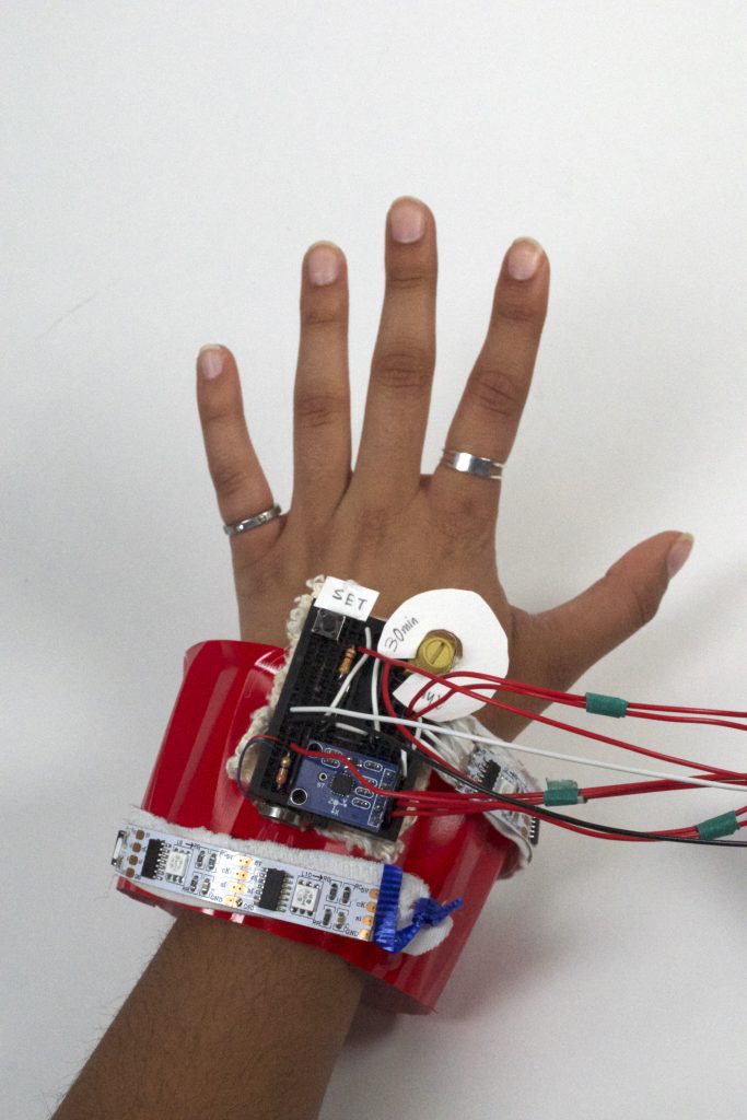
This photo shows how the prototype bracelet would be worn on the user.
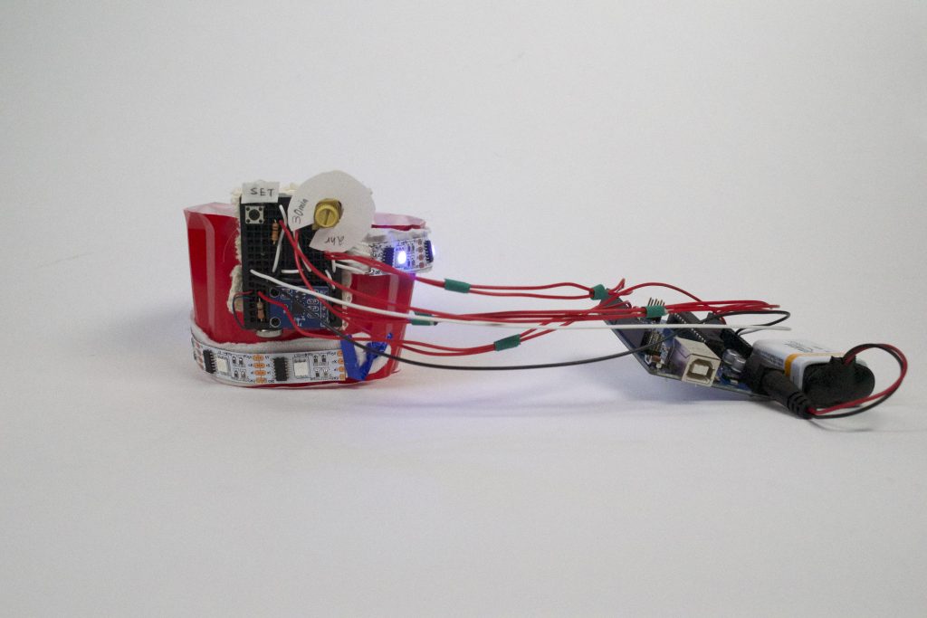
Above is an example of how the bracelet would look once the user has reached their daily limit.

This photograph depicts the features available to the user – specifically, the ability to set a daily limit of phone use, the LEDs indicating time spent, and the buzzing functionality of the bracelet when the user has reached their limit (bottom left of breadboard).

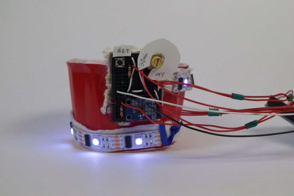
This picture illustrates the bracelet indicating an amount of phone use when the user has not reached their daily limit.
Process:
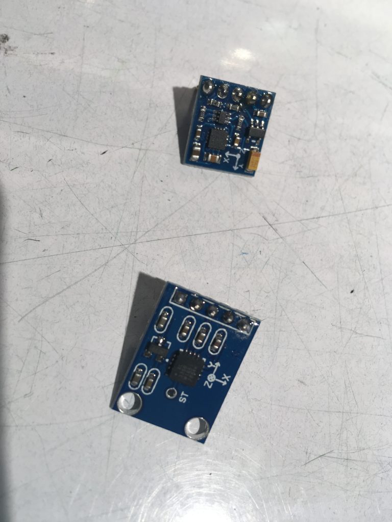
This photo illustrates the first major decision I made in this project, specifically choosing an appropriate sensor. In this picture, I was deciding between using an analog accelerometer and a digital accelerometer. At first, I tested a digital accelerometer, but due to the simplicity software wise of the analog accelerometer, I decided to use that instead. I also briefly considering using a tilt sensor, for simplicity purposes, but decided against it because of the limited amount of data I would be able to receive from it.

One major decision point during this project considered the form of its final state. I wanted to stick to my original vision of a bracelet, but there were many different ways implement that. This picture shows some of my earlier thoughts of creating some sort of static structure to mount the Arduino and breadboard onto, with the LED strip wrapping around the user’s wrist sort of like a strap.

This picture shows the final breadboard I used with all the electronic components excluding the Arduino/Power source. In the end, I decided to choose a bangle style bracelet, mainly for ease of creation and testing purposes. Condensing the breadboard and figuring out how to most efficiently mount the parts was one of the most technically challenging aspects of this project. This image shows that process about halfway complete.
Discussion:
Overall, I was satisfied with the technical functionalities of this project and my ability to make the best of trying out new components to use and being adaptable when testing didn’t work. I think the one aspect where I was definitely disappointed with the final result was aesthetics. Because the project required so many different electronic components and wiring in a specific way, I didn’t have enough time to work on the appearance of the final project. Additionally, the main functionality depended on accelerometer data, and when testing these data values, I was more concerned with simply mounting the breadboard and LED on some sort of physical structure to begin getting values, rather than making sure the form was as visually appealing as it could be. I think if I were to redo this project, I would first create the physical model and then figure out how to do the wiring and mounting aspect, rather than vice versa, as I did.
One of the main surprises in this project was the ease of getting values from the accelerometer. I assumed that figuring out the correct orientation and values for x/y/z would be the most challenging part of this project, but it turned out to be pretty simple, which I had not predicted. On the contrary, figuring out how to properly send data to LED lights and control them the way I wished to turned out to take much more time than I expected. I also added more components than I originally thought I would, specifically the vibrating motor, button and potentiometer. I think those aspects were necessary to make the project more practical, but also distracted from the main functionality, being the light up of the LED using data from the accelerometer.
Going into this project, I prioritized aesthetics last because I believed that I could more creatively troubleshoot that aspect rather than technical/electronic bugs and fixes. However, now I think that it is actually the opposite and when it comes to technical challenges, I am very creative and adaptable in my approaches, but when it comes to visual or physical design, I am more rigid in changing my original vision and it is harder for me to figure out a way to get across the same experience for the user when problem solving under pressure or time. Also, I didn’t set aside as much isolated time for ideation and brainstorming for this project as I did for the first project, and as a result my ideas were less creative. I have learned that it works better for me to set aside even short blocks of time on different days only devoted to thinking about new ideas, rather than one large block or doing it in combination with other activities (such as thinking when I workout or get food).
I don’t plan on building another iteration of this project, however, if I were to build onto what I have already, I would do a major redesign to make it more visually appealing and also do a little more research in how phone use can be detected from hand/wrist motion, because I think if my bracelet were to be used by real people, it would turn out to be unpredictable and possibly unreliable. Additionally, I would make some of its features digital – specifically, the functionality of setting a daily limit of phone use – in order to condense the physical size of it and remove unnecessary physical components (the button and potentiometer).
Technical Information:
Because I was not able to properly format all of my code into WordPress, I decided to show the following code snippet. The two functions shown below demonstrate my algorithm for 1) calculating a user-specified daily limit and 2) displaying the amount of time spent on the phone visually.
In the first function, I came up with a simple mathematical formula to help the user choose their goal. Specifically, a low-high range would be set on the bracelet physically, and from where the user set the potentiometer within that range, a limit would be calculated. This part of the code was challenging for me because I had not used floats in Arduino before, but they were necessary in order to calculate the limit (since a fraction over is calculated in line 3 and if this variable is set as an int, the limit would always be 0).
In the second function, the code loops through each LED individually and checks whether that LED index is greater than the percent of time out of the limit spent on the phone, divided by 10. This is because the percent is out of 100, but each LED is indexed from 0-8. Because there are 9 LEDs (this was what I had to work with), not 10, one challenge I had was figuring out a way to indicate to the user that 100% of their limit was met. For that reason, I decided to use the vibrating motor to indicate that the limit was met, rather than adding an additional LED or some other type of output.
int getLimit(int pot) {
  float range = (float)(hi - lo);
  float dec = (float)(pot / 1024.0);
  float change = (float)(range * dec);
  int n = lo + change; ;
  return n;
}

void updateBand(int percent) {
  for (int i = i; i < strip.numPixels(); i++) {
  if ((percent / 10) >= i) strip.setPixelColor(i - 1,   Color(255, 255, 255));
  else strip.setPixelColor(i, Color(0, 0, 0));
  }
  strip.show();
}
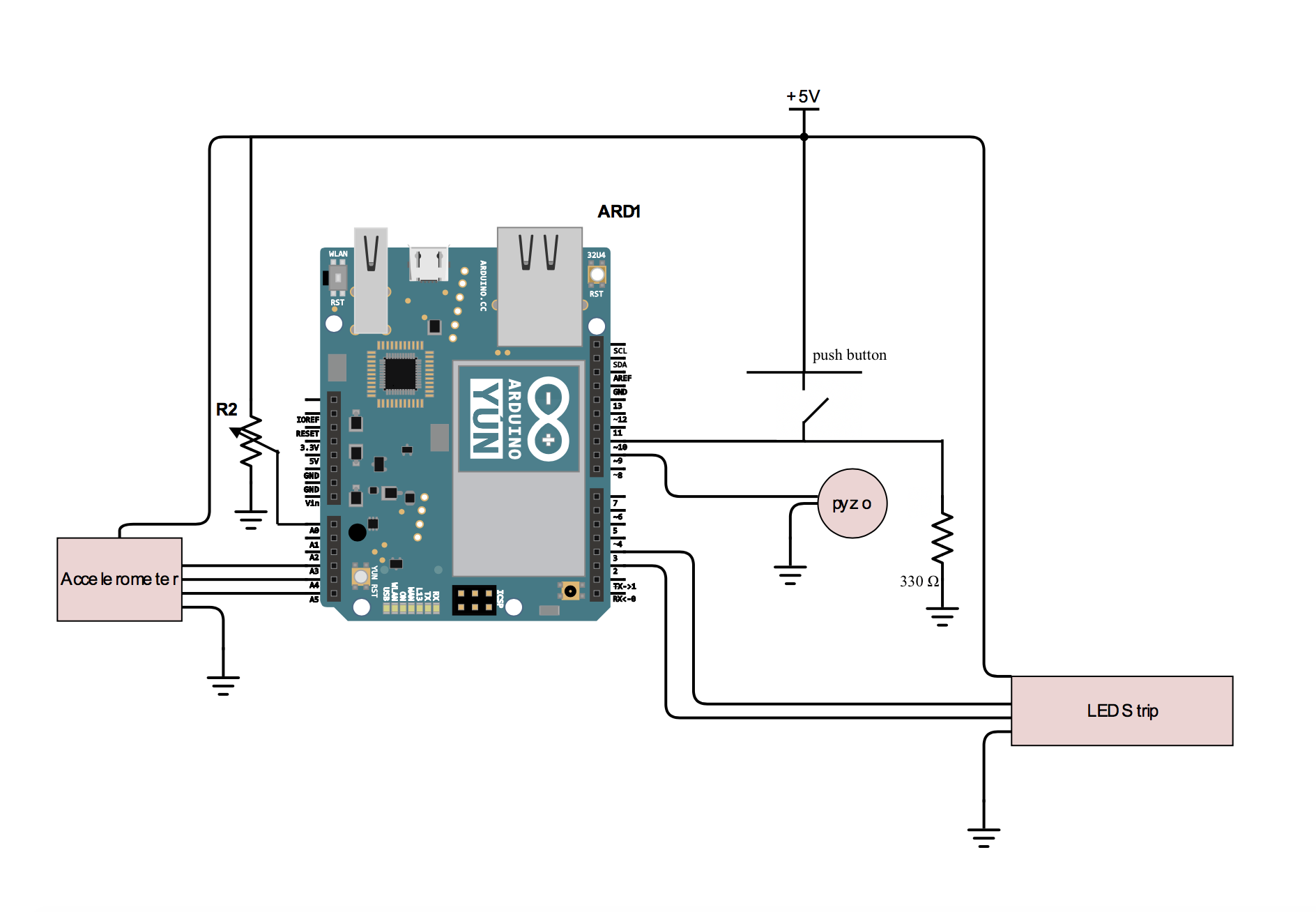
Schematic
Leave a Reply
You must be logged in to post a comment.