
The Weather Light is a device that tracks temperature and the amount of ambient light and changes the color of an RGB LED strip to inform the user of the current weather conditions. For example, a high UV reading will make the light more purple, while a high temperature reading will make the light more red.
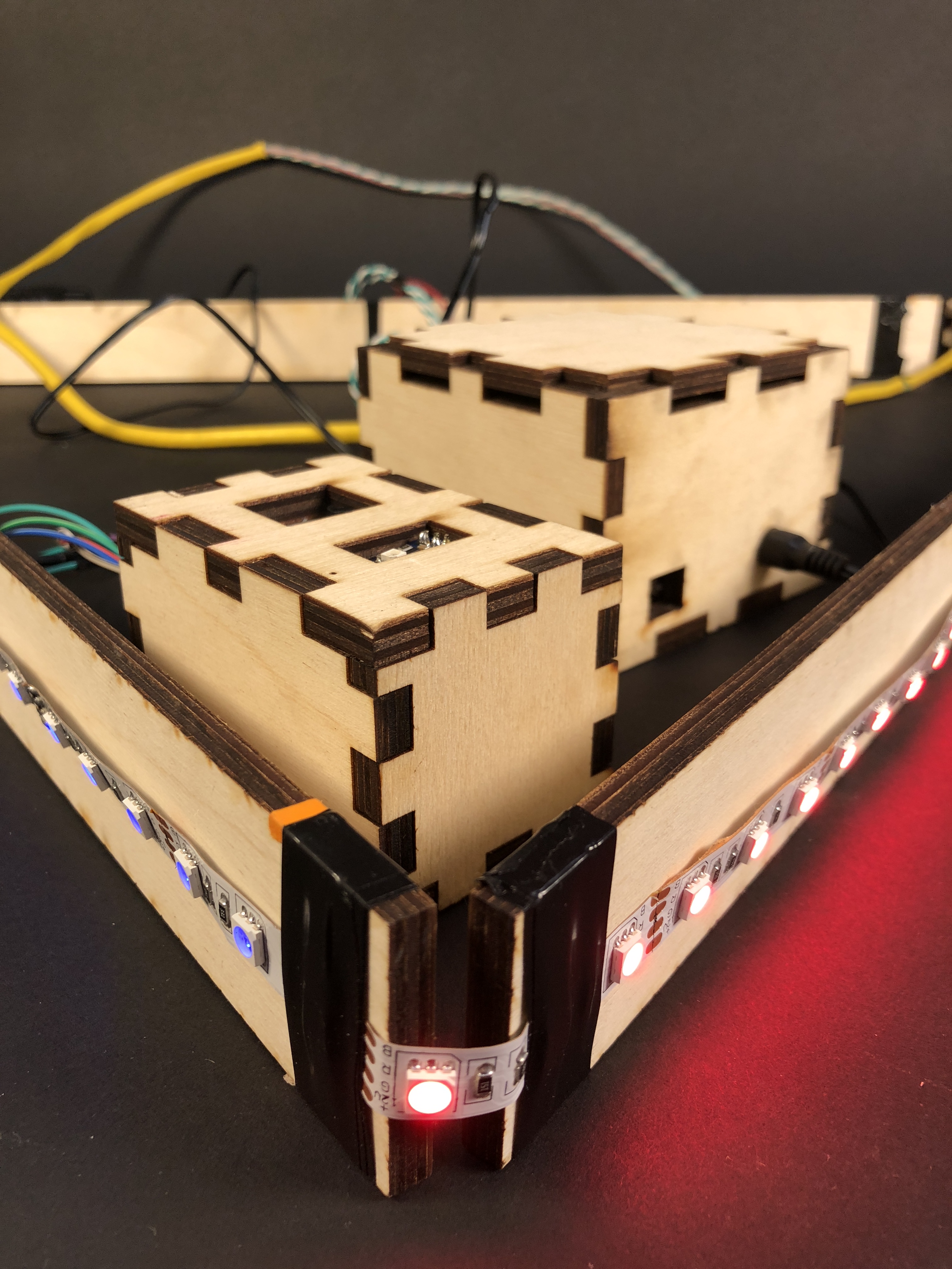
Overall View of the Weather Light
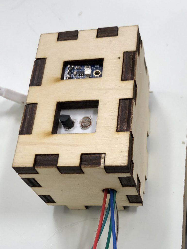
Detail of the Sensor Unit
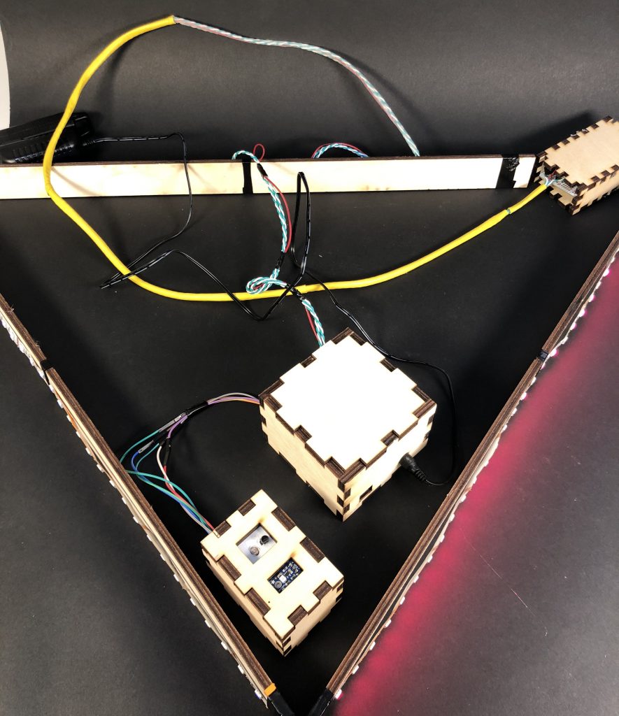
Overall scale of the Weather Light
The Process
The original idea was to have a light strip match the color of the sky. The most difficult part of the process was figuring out how to accurately measure the brightness and color of the sky. At first I tried using three photoresistors with a red, green and blue filter over each one. As a quick and easy prototype, each photoresistor was linked to an LED with its respective color.
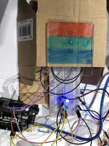
Colored Filters Prototype
I used colored lights on my phone to calibrate the photoresistors, but the when trying this system with actual sunlight each photoresistor gave nearly identical values. This would make for a very boring weather light that only ever changed at sunset and sunrise.
I decided to change my original idea. Instead of displaying the color of the sky, the light-strip would change based on the weather. I added a temperature and UV sensor, and removed two of the photoresistors. I also replaced the system of three LEDs with an RGB light-strip.
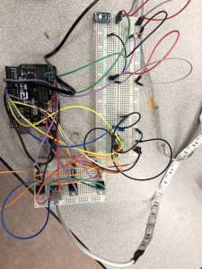
Breadboard Prototype with new sensors and LED Light strip
With the addition of the UV and temp sensors, the Weather light took its final from.
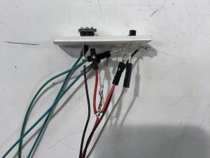
Detail of the Sensors
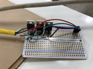
Detail of the MOSFET board
Taking the breadboard design to a presentable form was fairly straightforward. The Lightstrip was soldered to the same board as the MOSFETs. The sensors were mounted on a piece of foam-core to secure them. I laser cut three boxes: one for the sensors, one for the MOSFETs and one for the Arduino. I also cut three pieces of wood to make a baking for the lightstrip. Because the sensor unit needs to be outside, and the lights should be able to be placed on a wall or ceiling, I used 3 ft long cables between the boxes.
Technical Information
Schematic
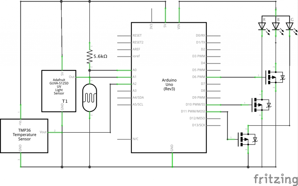
Schematic
Code
int cellR = A0;
int uvPin = A1;
int tmpPin = A2;

int redPin = 10;
int greenPin = 9;
int bluePin = 6;

void setup() {
 pinMode(cellR, INPUT);
 pinMode(uvPin, INPUT);
 pinMode(tmpPin, INPUT);

pinMode(redPin, OUTPUT);
 pinMode(greenPin, OUTPUT);
 pinMode(bluePin, OUTPUT);

 Serial.begin(9600); // starts serial communication at 9,600 baud (the rate)
}

void setColor(int red, int green, int blue)
{
 #ifdef COMMON_ANODE

#endif
 analogWrite(redPin, red);
 analogWrite(greenPin, green);
 analogWrite(bluePin, blue);
}

void loop() {
 int valR;
 int valUV;
 int r, g, b;

//convert voltage to farenhieght
 int rawvoltage = analogRead(tmpPin);
 float millivolts = (rawvoltage/1024.0) * 5000;
 float tmp = millivolts/10;

 valR = analogRead(cellR); // do the analog read and store the value and convert to rgb data
 valUV = analogRead(uvPin);

//Serial Prints for Debuging
 Serial.print(rawvoltage);
 Serial.println("R " + String(valR) + " UV " + String(valUV) + " TEMP " + String(tmp));
 delay(20); // slow the loop down a bit before it repeats

//Values are set for indoor testing use
 if (valUV >= 512){
 setColor(valUV/4, 0, valUV/4);
 }

 else if (valR < 200){
 setColor(valR/4, valR/4, valR/4);
 }
 else if (valR >= 900){
 setColor(0, 0, 0);
 }
 else if (tmp >= 60){
 for (r = 0; r < rawvoltage/4 ; r++){
 setColor(r, 0, valUV);
 }
 for (r = rawvoltage/4; r > 0; r--){
 setColor(r, 0, valUV);
 }
 }

else if (tmp <= 20){
 for (b = 20; b < rawvoltage/4 ; r++){
 setColor(0, b-20, b);
 }
 for (b = rawvoltage/4; b > 20; r--){
 setColor(0, b-20, b);
 }
 }
}
Discussion
Although the Weather Light was satisfactory I feel that there is more I could have done. I only used three sensors, and one LED strip. If I had had more time (and the arduino had more pins), I would have added a second or third light strip to better display weather information. I would have also liked to have more data to calibrate, as I only was able to test the project on rainy and overcast days.
Because my initial idea was to display the color of the sky I tried to use basic image processing to get that data. I used openCV in python to try and make this work, but could not install a specific dependency for an unknown reason. I would like to try and use this software on a different project and get it working.
The light strip I used was also fairly unreliable. The color was displayed correctly on the first third of the strip, but the red channel dropped out for the rest. It would also turn off and on if it was bumped. I tried to solve this by soldering it to a board but this problem continued. Even though the light strip itself was finicky, I learned how to use the p-channel MOSFETs to power it. I also learned what RGB values created what colors.
Leave a Reply
You must be logged in to post a comment.