Introduction:
Our goal with this project was to create an assistive device to help improve a part of someone’s day-to-day life. We teamed up with Wilma, a local elderly woman, and met with her to develop a product that addresses a personal problem that she has. During our initial meeting, she noted how she has difficulty remembering the contents of her basement freezer. We quickly identified this as a problem that we could address. Because she finds it difficult to go downstairs, Wilma wanted a way to know exactly what was in her downstairs freezer without having to walk down from the main floor to check. We set out to develop a way for Wilma to keep track of her freezer inventory from the main floor. To see details on our first iteration, refer to our documentation here.
What we built:
Our final product allows for Wilma to easily track the inventory of her freezer. As she uses or buys new food items, she can log the changes in quantity using a device nearby her downstairs freezer. Wilma can do this by selecting a card from a stack that includes all of her most frequently used food items, and tapping the card against the device. The display then shows the food and its current quantity, which can be updated with two buttons (plus/minus). As Wilma updates her inventory from the downstairs freezer, the device on the first floor instantly updates to reflect the changes. While Wilma is upstairs, she can scroll through a list showing what foods she has and how many she has of them, which saves her a trip downstairs before she goes on a shopping run.
Overall Photo:
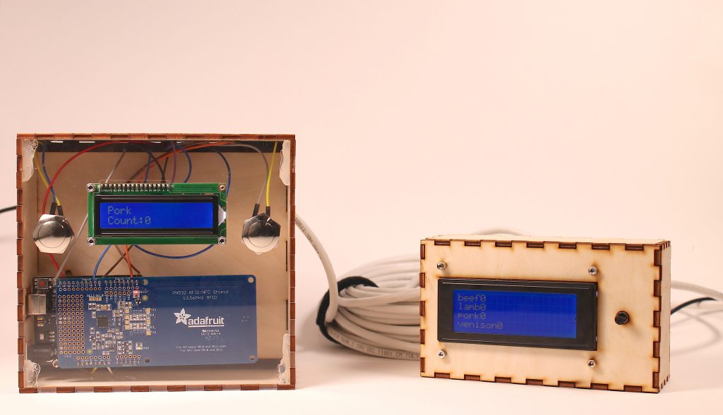
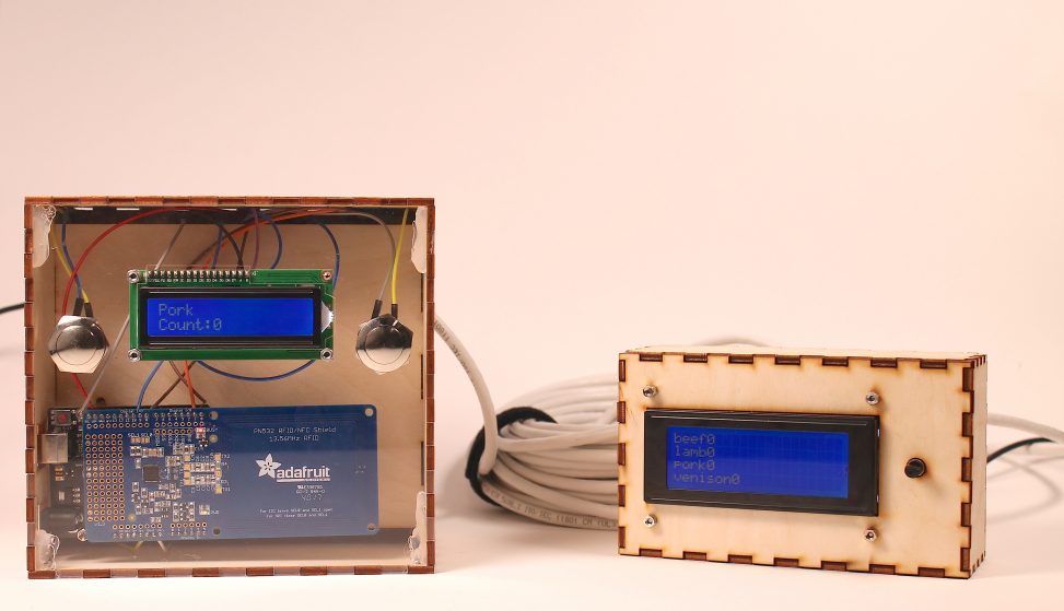
Overall Photo of Device : Scanner box to be put in the basement (Left), and display box to be put on the first floor (Right)
Detail Photos:
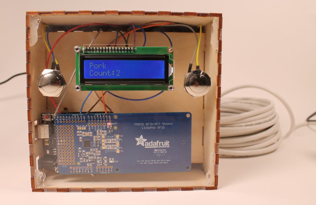
Close-up of scanner box – The front plate is transparent to see where the scanner is
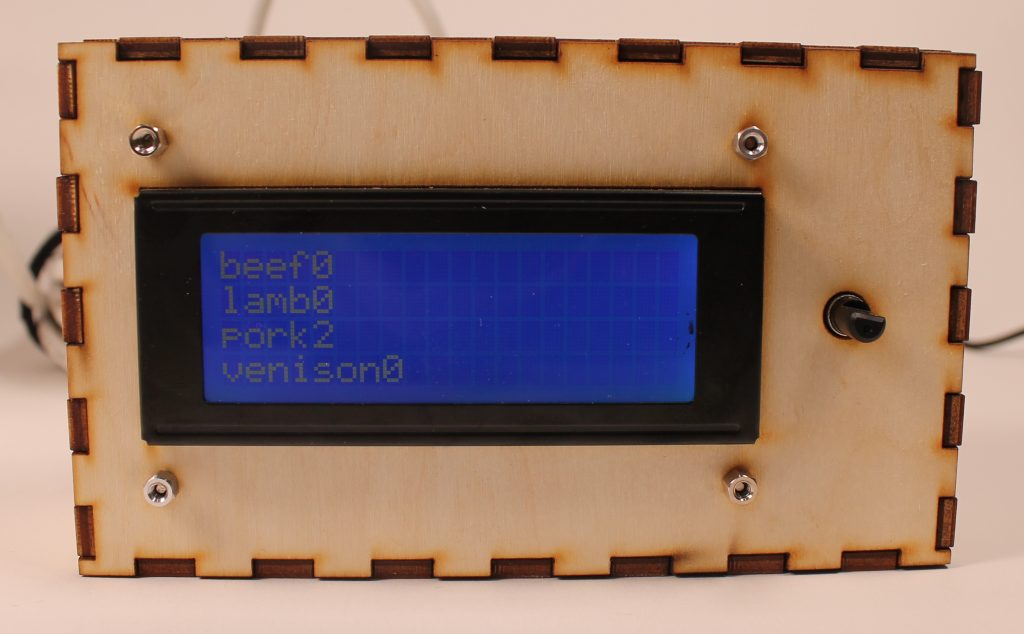
Close up of display box – Number of each food item will be updated accordingly to the basement scanner box input
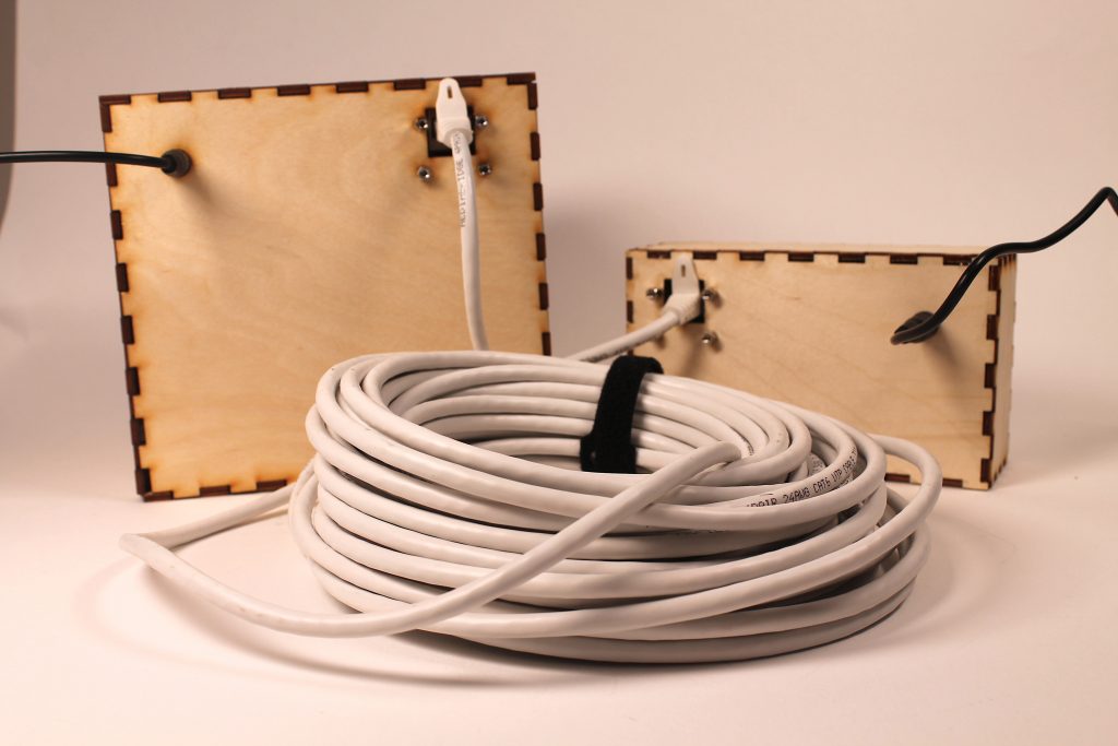
The two boxes in the basement and first floor are connected with an Ethernet cable
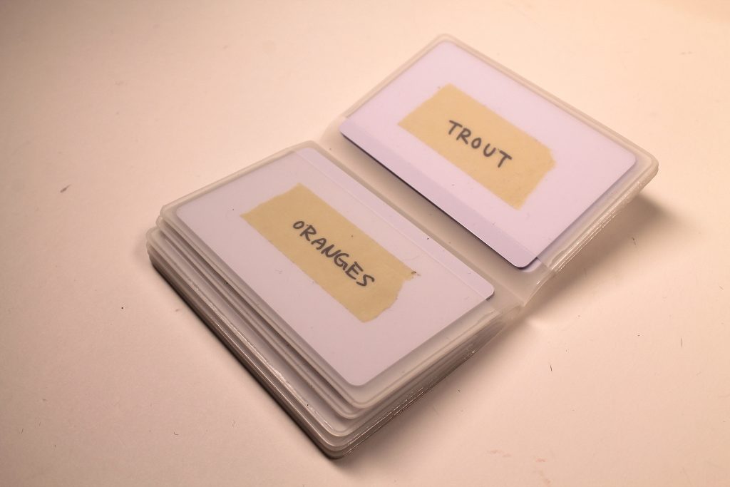
Different cards are available for scanning
In Use Photos:
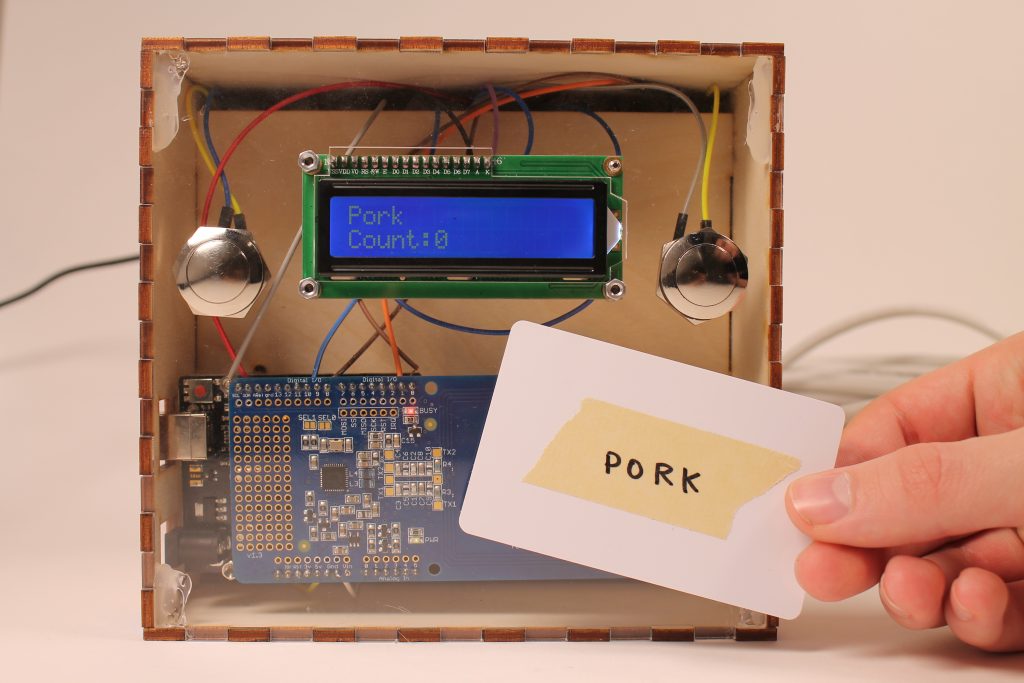
A food item card must be scanned to update its count
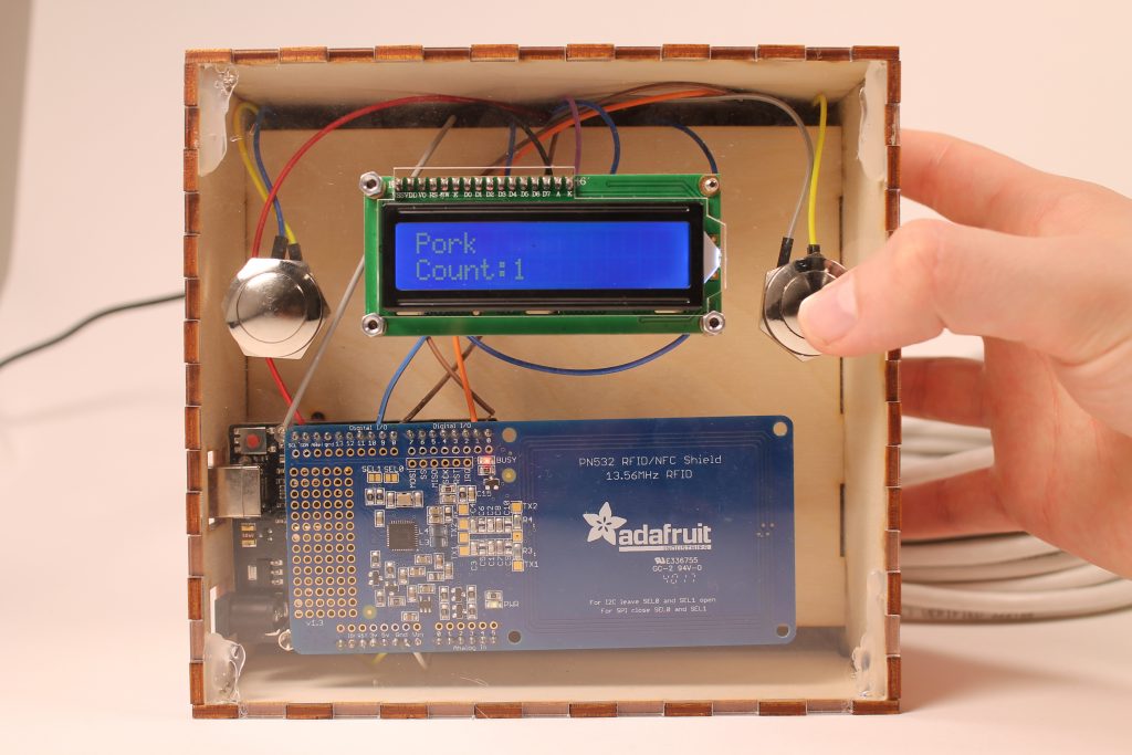
Wilma can then press the plus or minus button to update the count of the food
Wilma can easily keep track of her groceries with the RFID cards
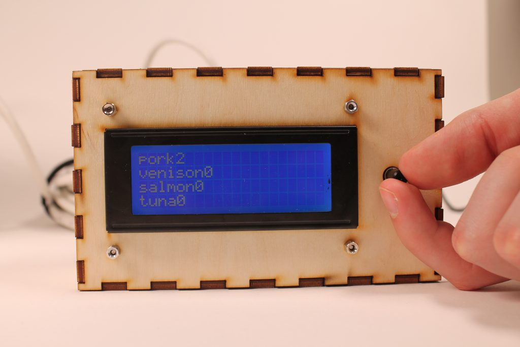
The updated count will then be reflected on the first floor display box, and the user can rotate the switch to scroll through the display for different food items
Wilma can scroll through her freezer inventory on the first floor
Narrative:
Wilma is on the main floor of her house when she realizes she needs to go grocery shopping. She does not remember what she bought a couple weeks earlier or what her and her husband have been eating recently. Instead of walking downstairs to check her freezer, she goes to the display next to the door and scrolls through the list of her freezer inventory. Now that she has a good idea of what she needs to buy, Wilma is able to go grocery shopping to stock up on carrots, potatoes, and beef.
When Wilma comes back from the store, she goes downstairs to put her groceries in the freezer. After Wilma places the beef in the freezer, she taps the “beef” card on our gadget, and adds one to the beef count. Later that night, Wilma is looking through her freezer inventory upstairs, trying to decide what to make for dinner. Now that her freezer is fully stocked with beef, carrots, and potatoes, she decides to make beef stew for her and her husband.
How we got here:
We went through many iterations of this product before it took on its final appearance. Originally, this product started out as a physical representation of a shopping list. Downstairs, nearby the freezer, we made many blocks that could be placed on a board. On the upstairs display, the items on the downstairs board were reflected on a small LCD display, to serve as a reminder before Wilma decides to go shopping.
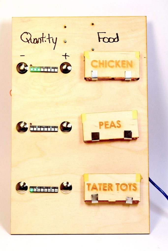
Our prototype using food blocks
Even before we arrived at this design, we went through several iterations to perfect the block detecting mechanism. The main idea is that by adding the block to the board, the block would complete a voltage divider circuit. Using this circuit, we could detect which block is on the board. One of the big challenges we faced initially was to get good electrical contact between the blocks and the board.
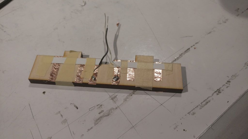
This is how we initially tried to detect the block using conductive tape.
Although the shopping board design had its strengths (we got feedback from Wilma and others that they really liked the tactile element of our project), we decided that we needed to revamp this project in order to make it truly practical. One issue that was noted by several people was that the blocks were too bulky. This made it impractical to make many blocks, because it would take up too much physical space. Another problem with our initial design was that it could only display three food items at a time. For our final design, we wanted to make a product that was more flexible than this. Overall, people seemed to like our solution to address Wilma’s accessibility problem. Wilma herself noted that it would be useful to know what is in her freezer downstairs without having to actually go downstairs.
For our final product, we wanted to draw from the strengths of our original design (physical element and downstairs/upstairs convenience), while addressing some of the shortcomings (bulkiness, limited number of food items). The solution we came up for the bulkiness issue, that also made the device more reliable overall), was to swap the blocks for RFID cards. The RFID cards, roughly the size and thickness of a credit card, are stored neatly in a holder nearby the downstairs device. To address the limited number of food items, we implemented a scrolling feature that takes advantage of a rotary encoder. We found that this was an intuitive way to search through large lists of food.
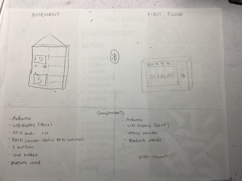
Image of brainstorming process for our initial iteration of the final design
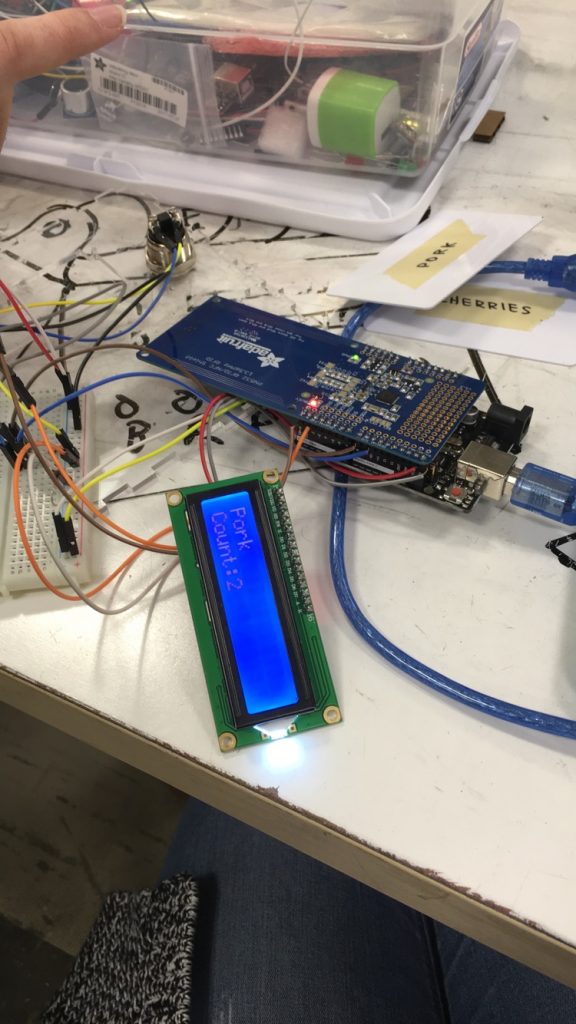
A picture to show when we successfully set up the scanner and the display with the RFID cards

Picture to show how the food items were displayed on the display box
Even to get to this point, however, we ran into many technical issues. One of the larger issues that we had was how to get the two arduinos to communicate with one another. We started by simply connecting the arduinos via the tx and rx pins and trying to send over a simple string. From there we tried to get the string to become a usable variable. Once we were able to get that done the issue was how to send over the information we wanted, two different numbers and allow the receiving arduino to know which number corresponded to which variable. We were able to get it to work by adding each incoming character as a string and then using a colon as an identifier to differentiate the two different variables. Then we converted the separated strings to integers which we were then able to use to update the spot in the arrays for the food and counts.
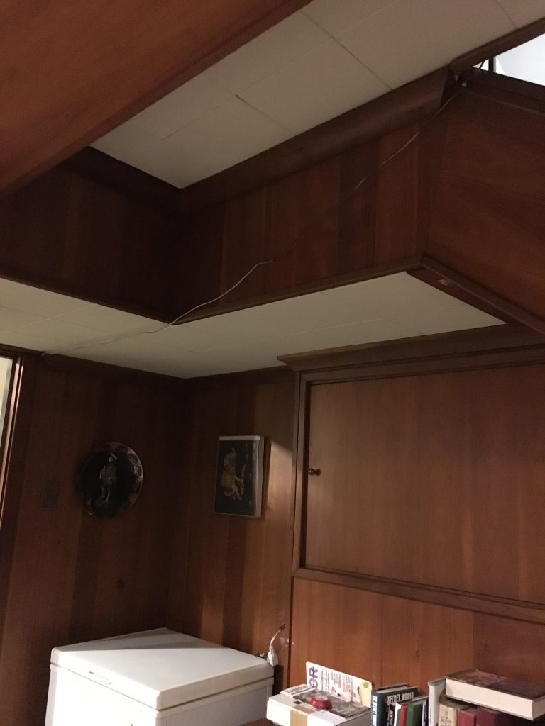
Another aspect of our project that we changed from our initial iteration is the method for communicating between the two arduinos. We initially wanted to have them communicate wirelessly using bluetooth. However, we realized that this may be problematic if the arduinos are placed on separate floors, and communication becomes unreliable. The next option we came up with was an Ethernet cable, which would allow reliable communication. After visiting Wilma’s house, we were able to confirm that this was a viable option. There was already a telephone cable running from the first floor to the basement, so adding another cable would not be an issue. Moreover, there were outlets near the basement freezer, which allows easy installation of the device.
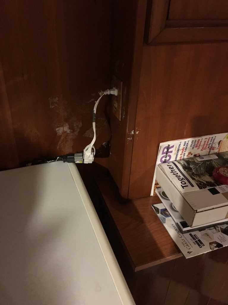
Outlet near the freezer – allows easy installation of our device
Telephone cord running from freezer (seen in bottom left corner of picture) to upstairs through the staircase
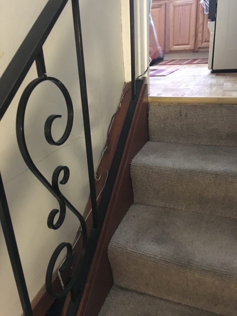
Gap between wall and stairs so cables can run through
Conclusions:
The final crit was very valuable in giving us ideas of how we could improve our project in the future if we were to move forward as well as allowing us to see what we did well. I think people liked the overall functionality of our project. The ability to have the two separate systems talk to each other and have the different displays update together seemed to be a useful idea that we implemented well. There were a couple ideas brought up during the final crit that seemed to make sense for future iterations of the product. Several people commented on different ways to display the content on the upstairs device. One person made the fair point that it would be useful to “be able to sort (the) display by number.”. We also noticed that it would be more helpful for Wilma if the display box is more interactive, such as it acting as a shopping list and reminding her to buy a certain food item.
We found that working with an older person was an interesting process. In the initial stage when trying to identify a problem, it was difficult as they have already accustomed to a certain lifestyle, and were wary of introducing technology since they did not grow up with it. However, we appreciated how cooperative Wilma was, as she came to our meeting with ideas in her mind about certain issues technology could solve. Also, we realized that showcasing our past projects was very effective for introducing new ideas. If we have another opportunity to work with an older person, we would want to have more examples of how technology can help someone’s life, to provide a better understanding of physical computing. Visiting Wilma’s house was also a major step in the process, as it immediately provided us with a more realistic sense of how she may use this device and how it can be implemented in her house.
In terms of the iteration process, we recognized the importance of exploring different options when hitting obstacles, instead of trying to pursue the same method for a long time period. Especially with the issue for communication between the two arduinos, we were able to find the best method by fast paced trial and error. When working under a time pressure, we found that it was important to keep open perspectives and explore other viable options.
Overall, we really enjoyed working with Wilma, and are happy with how our final project turned out. Hopefully, Wilma will find our device useful in keeping track of the foods she needs to buy.
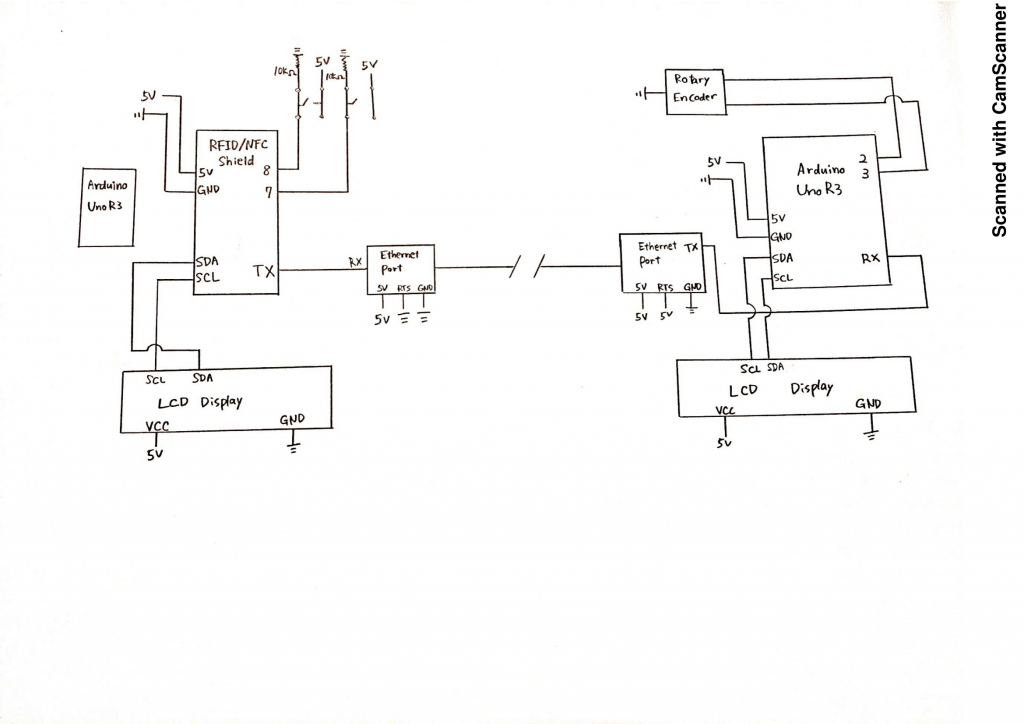
Circuit Diagram:
Technical Details:
Code for Basement:
/**************************************************************************/
/*!
 @file readMifareClassic.pde
 @author Adafruit Industries
 @license BSD (see license.txt)

This example will wait for any ISO14443A card or tag, and
 depending on the size of the UID will attempt to read from it.

If the card has a 4-byte UID it is probably a Mifare
 Classic card, and the following steps are taken:

Reads the 4 byte (32 bit) ID of a MiFare Classic card.
 Since the classic cards have only 32 bit identifiers you can stick
 them in a single variable and use that to compare card ID's as a
 number. This doesn't work for ultralight cards that have longer 7
 byte IDs!

Note that you need the baud rate to be 115200 because we need to
 print out the data and read from the card at the same time!

This is an example sketch for the Adafruit PN532 NFC/RFID breakout boards
 This library works with the Adafruit NFC breakout
 ----> https://www.adafruit.com/products/364

Check out the links above for our tutorials and wiring diagrams
 These chips use SPI to communicate, 4 required to interface

Adafruit invests time and resources providing this open source code,
 please support Adafruit and open-source hardware by purchasing
 products from Adafruit!
*/
/**************************************************************************/
#include <Wire.h>
#include <SPI.h>
#include <Adafruit_PN532.h>
#include <LiquidCrystal_I2C.h>
#include <Math.h>
LiquidCrystal_I2C lcd(0x27, 16, 2);
#ifdef __AVR__
#include <avr/power.h>
#endif

// If using the breakout or shield with I2C, define just the pins connected
// to the IRQ and reset lines. Use the values below (2, 3) for the shield!
#define PN532_IRQ (2)
#define PN532_RESET (3) // Not connected by default on the NFC Shield

// Uncomment just _one_ line below depending on how your breakout or shield
// is connected to the Arduino:

// Use this line for a breakout with a hardware SPI connection. Note that
// the PN532 SCK, MOSI, and MISO pins need to be connected to the Arduino's
// hardware SPI SCK, MOSI, and MISO pins. On an Arduino Uno these are
// SCK = 13, MOSI = 11, MISO = 12. The SS line can be any digital IO pin.
//Adafruit_PN532 nfc(PN532_SS);

// Or use this line for a breakout or shield with an I2C connection:
Adafruit_PN532 nfc(PN532_IRQ, PN532_RESET);

#if defined(ARDUINO_ARCH_SAMD)
// for Zero, output on USB Serial console, remove line below if using programming port to program the Zero!
// also change #define in Adafruit_PN532.cpp library file
#define Serial SerialUSB
#endif
const int POSBUT = 8;
const int NEGBUT = 9;
int lastButP = 0;
int ButP = 0;
int lastButN = 0;
int ButN = 0;
int indexNum = 0;

char* foods[] {
 "Beef",
 "Lamb",
 "Pork",
 "Venison",
 "Salmon",
 "Tuna",
 "Cod",
 "Trout",
 "Shrimp",
 "Clams",
 "Strawberries",
 "Cherries",
 "Mixed fruits",
};
int counts[sizeof(foods) / 2] = {0};
const unsigned long idnums[sizeof(foods) / 2] = {
 1288439685,
 1828249131,
 969280133,
 2838093867,
 1903429509,
 1624895643,
 4041343644,
 1345447067,
 1343218843,
 1079115932,
 3491956869,
 756091013,
 1961469925,
};
uint32_t cardid = 0;
uint32_t lastcardid = 0;

void setup(void) {
 pinMode(POSBUT, INPUT);
 pinMode(NEGBUT, INPUT);
 Serial.begin(115200);
#ifndef ESP8266
 while (!Serial); // for Leonardo/Micro/Zero
#endif

nfc.begin();

uint32_t versiondata = nfc.getFirmwareVersion();
 if (! versiondata) {
   Serial.print("Didn't find PN53x board");
   while (1); // halt
 }
 // configure board to read RFID tags
 nfc.SAMConfig();
 // Initialize lcd
 lcd.init();
 lcd.backlight();

}


void loop(void) {
 //pin setup for buttons
 ButP = digitalRead(POSBUT);
 ButN = digitalRead(NEGBUT);
 uint8_t success;
 uint8_t uid[] = { 0, 0, 0, 0, 0, 0, 0 }; // Buffer to store the returned UID
 uint8_t uidLength; // Length of the UID (4 or 7 bytes depending on ISO14443A card type)

// Wait for an ISO14443A type cards (Mifare, etc.). When one is found
 // 'uid' will be populated with the UID, and uidLength will indicate
 // if the uid is 4 bytes (Mifare Classic) or 7 bytes (Mifare Ultralight)
 success = nfc.readPassiveTargetID(PN532_MIFARE_ISO14443A, uid, &uidLength, 20);
 if (success) {
    cardid = uid[0];
    cardid <<= 8;
    cardid |= uid[1];
    cardid <<= 8;
    cardid |= uid[2];
    cardid <<= 8;
    cardid |= uid[3];
    //new card detected!
    if (cardid != lastcardid) {
       for (int index = 0; index < sizeof(foods) / 2; index = index + 1) {
          if (idnums[index] == cardid) {
             indexNum = index;
          }
    }
    lcd.setCursor(0, 0);
    lcd.print(" ");
    lcd.setCursor(0, 1);
    lcd.print(" ");
   }
 }
 //check if button was pressed, and update count
 if (ButP == 1) {
    if (ButP != lastButP) {
       counts[indexNum] = counts[indexNum] + 1;
       Serial.print(String(indexNum));
       Serial.print(":");
       Serial.println(String(counts[indexNum]));
       lcd.setCursor(0, 1);
       lcd.print(" ");
    }
    delay(25);
 }
 else if (ButN == 1) {
    if (ButN != lastButN) {
       counts[indexNum] = counts[indexNum] - 1;
       if (counts[indexNum] < 0) {
          counts[indexNum] = 0;
       }
       Serial.print(String(indexNum));
       Serial.print(":");
       Serial.println(String(counts[indexNum]));
       lcd.setCursor(0, 1);
       lcd.print(" ");
    }
    delay(25);
 }
 lastButP = ButP;
 lastButN = ButN;
 lastcardid = cardid;

//display on lcd
 if (cardid != 0) {
    lcd.setCursor(0, 0);
    lcd.print(foods[indexNum]);
    lcd.setCursor(0, 1);
    lcd.print("Count:" + String(counts[indexNum]));
 }
}

Code for First Floor:
#include <Adafruit_PN532.h>

// Setting up the counter
int reading = 0;
int lowest = -24;
int highest = 0;
int changeamnt = 1;
int array[] = {1, 2, 3, 4, 5, 6, 7, 8};
// Timing for polling the encoder
unsigned long currentTime;
unsigned long lastTime;
int lcdreading = 0;

// Pin definitions
const int pinA = 2;
const int pinB = 3;
int change = 0;
// Storing the readings

boolean encA;
boolean encB;
boolean lastA = false;
#include <Wire.h>
#include <LiquidCrystal_I2C.h>
#include <Math.h>
LiquidCrystal_I2C lcd(0x27, 20, 4);
char* foods[] {
 "beef",
 "lamb",
 "pork",
 "venison",
 "salmon",
 "tuna",
 "cod",
 "trout",
 "shrimp",
 "clams",
 "strawberries",
 "cherries",
 "oranges",
 "apples",
 "mixed fruits"
};
int counts[sizeof(foods) / 2] = {0};
int index = 0;
const unsigned long idnums[sizeof(foods) / 2] = {
 1288439685,
 1828249131,
 969280133,
 2838093867,
 1903429509,
 1624895643,
 4041343644,
 1345447067,
 1343218843,
 1079115932,
 3491956869,
 756091013,
 1961469925
};
boolean stringComplete = false;
String inputString = "";
char rcvd;
String inString = "";
int a = 0;
int b = 0;
void setup() {
 // set the two pins as inputs with internal pullups
 pinMode(pinA, INPUT_PULLUP);
 pinMode(pinB, INPUT_PULLUP);
 // Set up the timing of the polling
 currentTime = millis();
 lastTime = currentTime;
 // Start the serial monitor for debugging
 lcd.init();
 lcd.backlight();
 Serial.begin(115200);
}


void loop()
{
 if (Serial.available() > 0) {
    int inChar = Serial.read();
    inString += (char)inChar;
    int lineIndex = inString.indexOf('\n');
    int colonIndex = inString.indexOf(':');
    if (inChar == '\n') {
       String indexNumS = inString.substring(0, colonIndex);
       String countNumS = inString.substring(colonIndex + 1, lineIndex);
       a = indexNumS.toInt();
       b = countNumS.toInt();
       counts[a] = b;
       Serial.println(a);
       Serial.println(b);
       inString = "";
    }
 }
 currentTime = millis();

if (currentTime >= (lastTime + 5))
 {
 // read the two pins
 encA = digitalRead(pinA);
 encB = digitalRead(pinB);
 // check if A has gone from high to low
    if ((!encA) && (lastA))
    {
    // check if B is high
       if (encB)
       {
       // clockwise
       if (reading + changeamnt <= highest)
          {
          reading = reading + changeamnt;
          change = 1;
          lcd.setCursor(0, 0);
          lcd.print(" ");
          lcd.setCursor(0, 1);
          lcd.print(" ");
          lcd.setCursor(0, 2);
          lcd.print(" ");
          lcd.setCursor(0, 3);
          lcd.print(" ");
       }
    }
 else
 {
 // anti-clockwise
    if (reading - changeamnt >= lowest)
    {
       reading = reading - changeamnt;
       change = -1;
       lcd.setCursor(0, 0);
       lcd.print(" ");
       lcd.setCursor(0, 1);
       lcd.print(" ");
       lcd.setCursor(0, 2);
       lcd.print(" ");
       lcd.setCursor(0, 3);
       lcd.print(" ");
    }
 }
 // Output reading for debugging
 Serial.print("Change ");
 Serial.println(change);
 Serial.println(reading);
 }
 // store reading of A and millis for next loop
 lastA = encA;
 lastTime = currentTime;
 lcdreading = (-1) * reading;

}
 if (lcdreading > 25 ) {
    lcdreading = 0;
 }
 Serial.print("lcdreading ");
 Serial.println(lcdreading);
 lcd.setCursor(0, 0);
 //lcd.print(" ");
 lcd.print(foods[lcdreading]);
 lcd.print(counts[lcdreading]);
 lcd.setCursor(0, 1);
 //lcd.print(" ");
 lcd.print(foods[lcdreading + 1]);
 lcd.print(counts[lcdreading + 1]);
 lcd.setCursor(0, 2);
 //lcd.print(" ");
 lcd.print(foods[lcdreading + 2]);
 lcd.print(counts[lcdreading + 2]);
 lcd.setCursor(0, 3);
 //lcd.print(" ");
 lcd.print(foods[lcdreading + 3]);
 lcd.print(counts[lcdreading + 3]);
}
Leave a Reply
You must be logged in to post a comment.