Read more about earlier stages in our project:
First meeting/ideation: https://courses.ideate.cmu.edu/60-223/s2019/work/interview-with-elinor/
First prototype: https://courses.ideate.cmu.edu/60-223/s2019/work/team-elinor-prototype-documentation/
What We Built
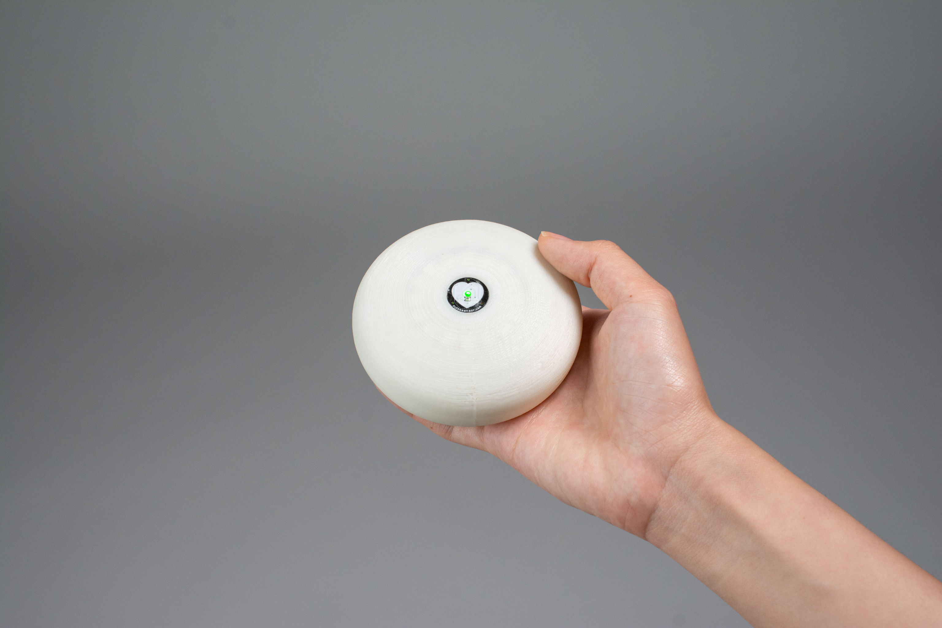
The “puck” is compact enough to be carried wherever Elinor goes and was designed with her hand size in mind.
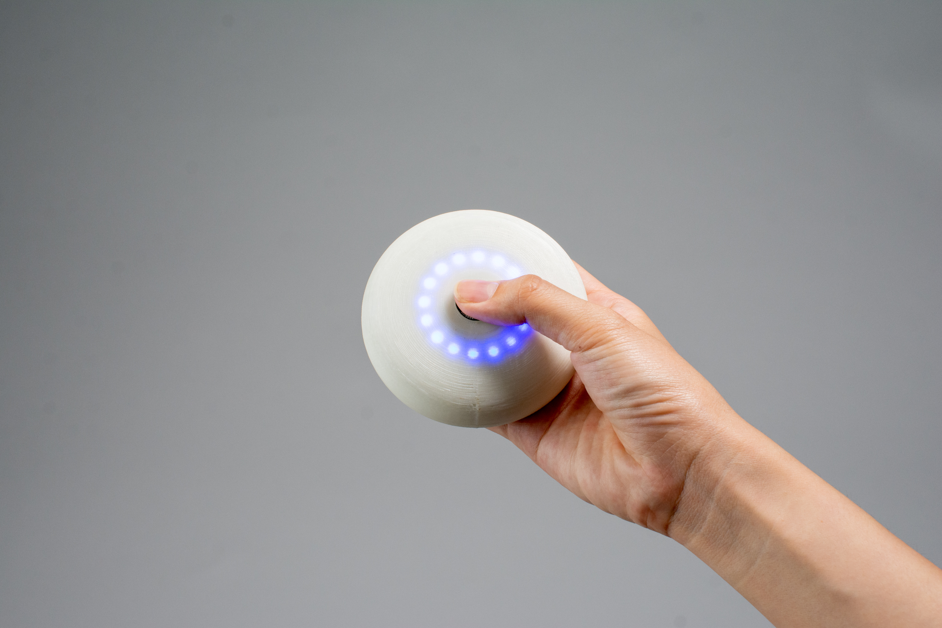
A sequence of blue pulses guides the rate of deep breathing.
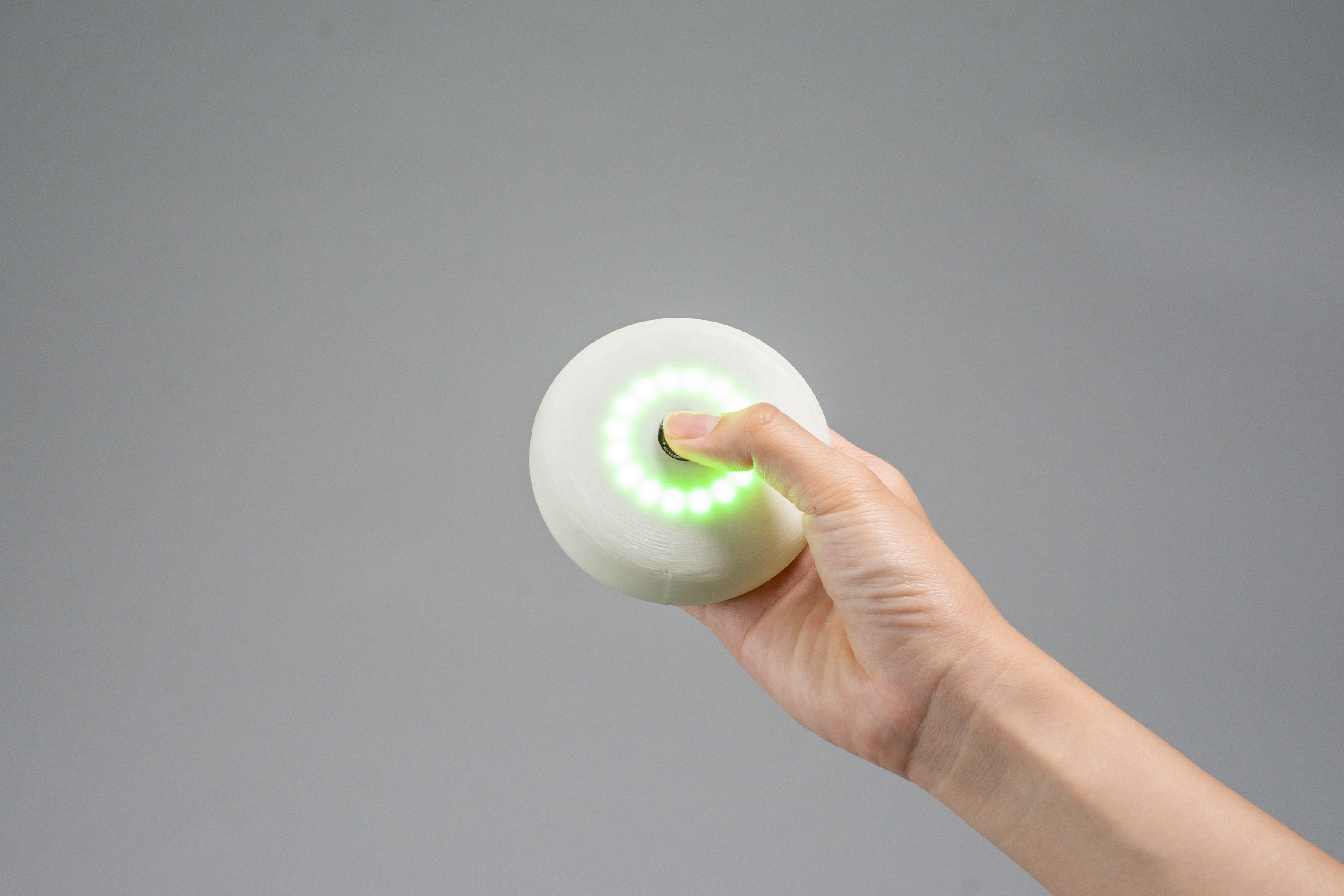
The ring of lights turns green to signal the end of a minute of deep breathing.
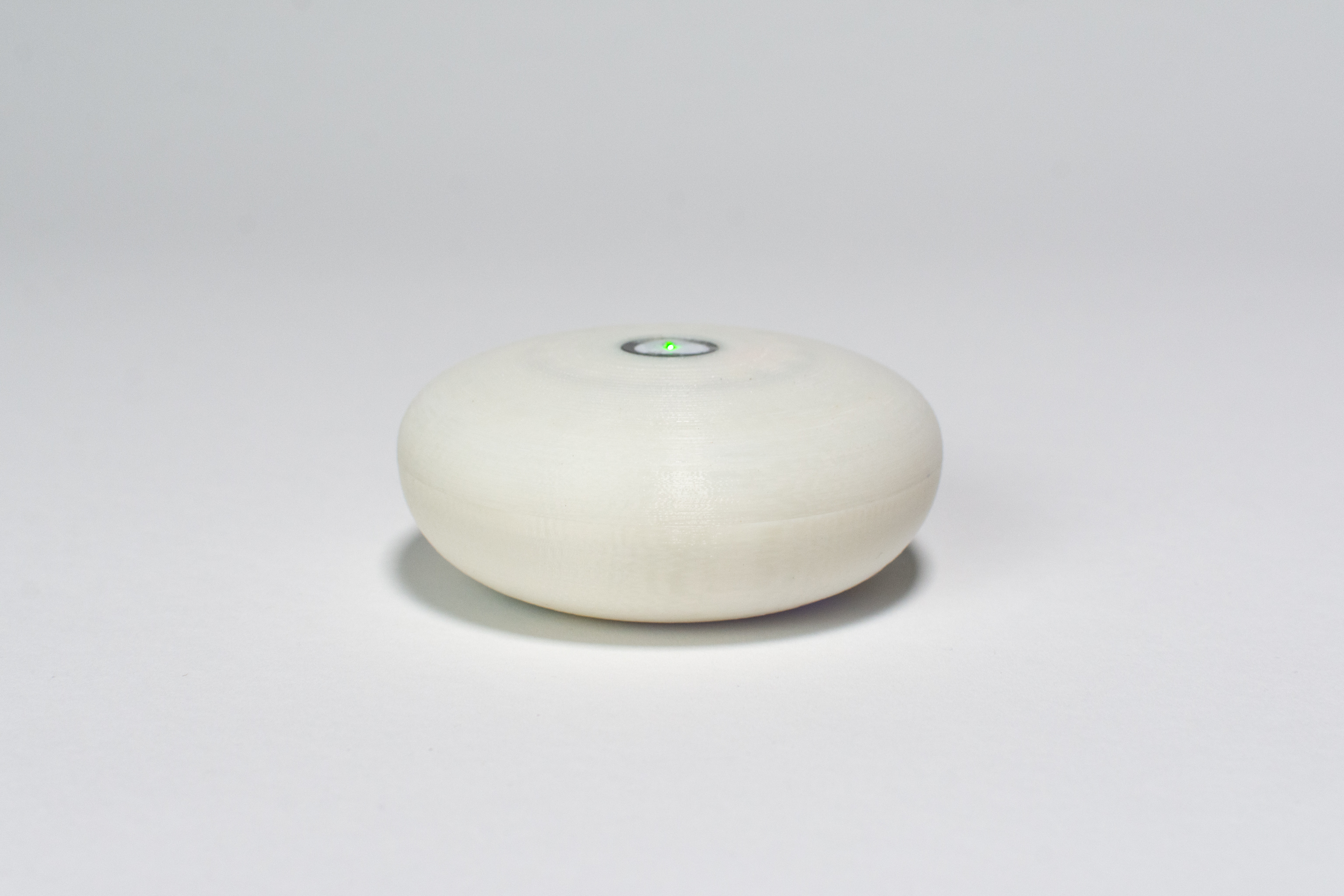
Inspired by smooth river stones, the puck was designed to be smooth and rounded for great ergonomics.
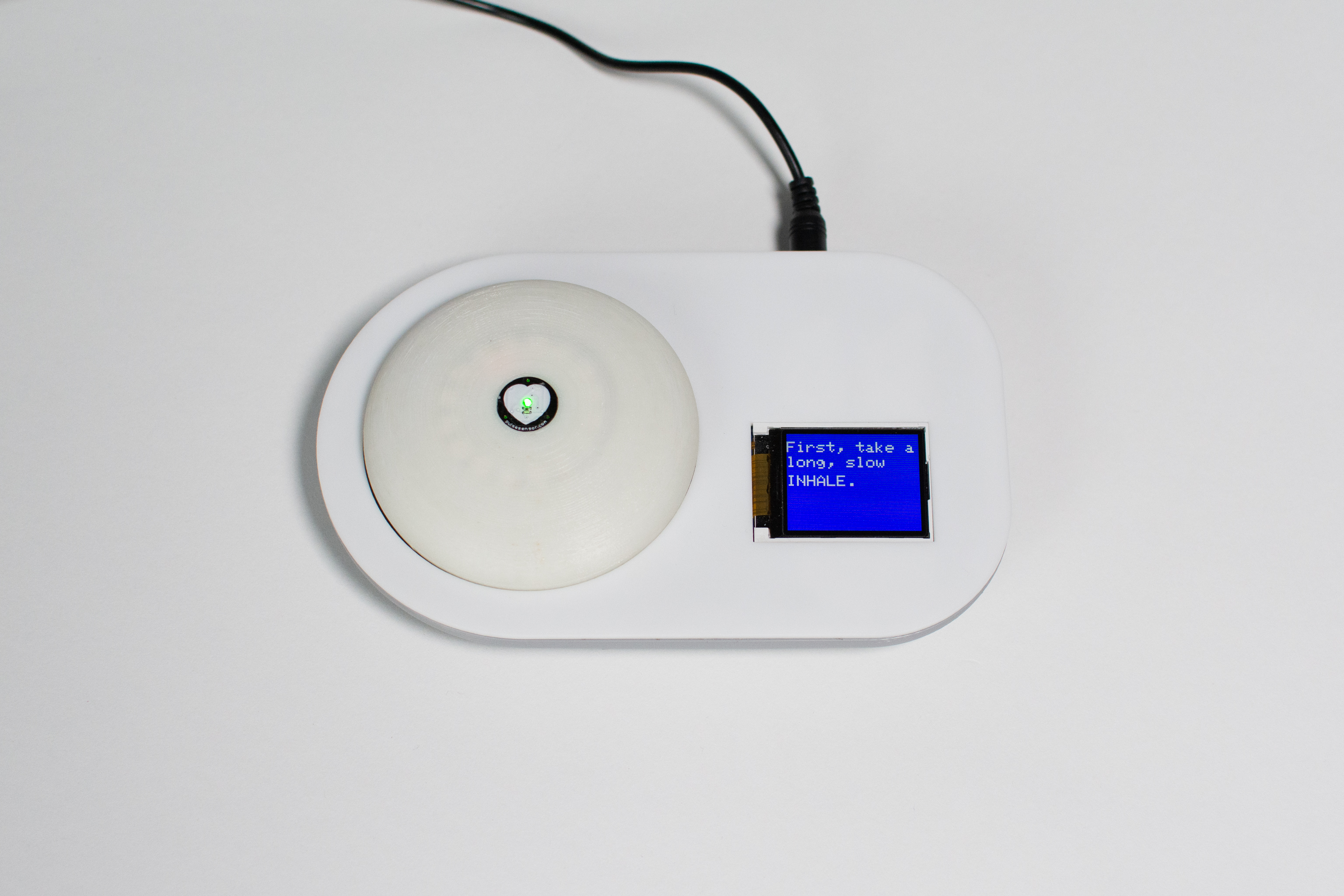
As the portable puck charges in the cable, a display guides Elinor through more mindfulness exercises.
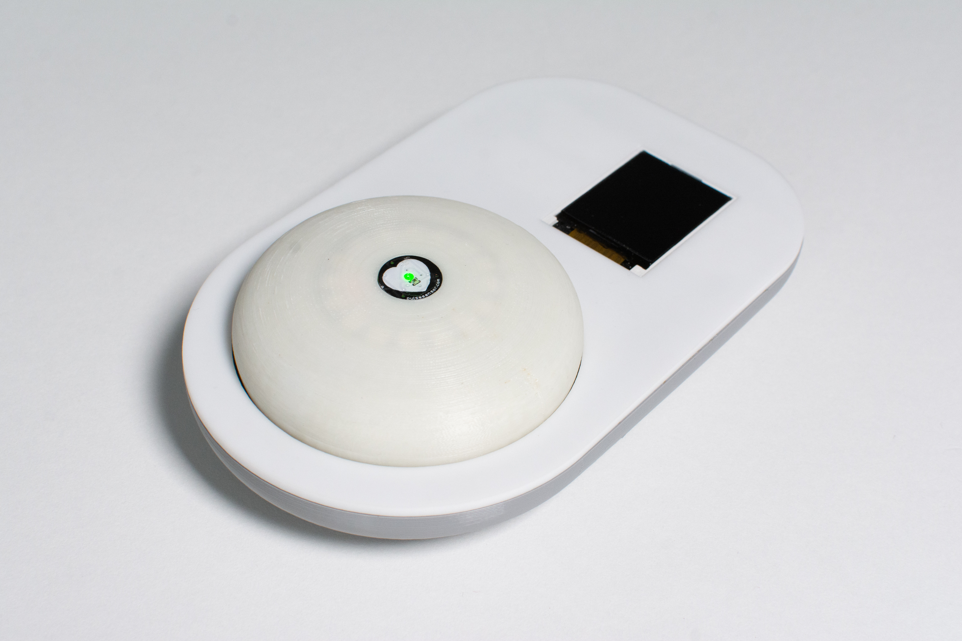
The puck and dock were designed together to be approachable and small enough to be placed on a nightstand or desk.
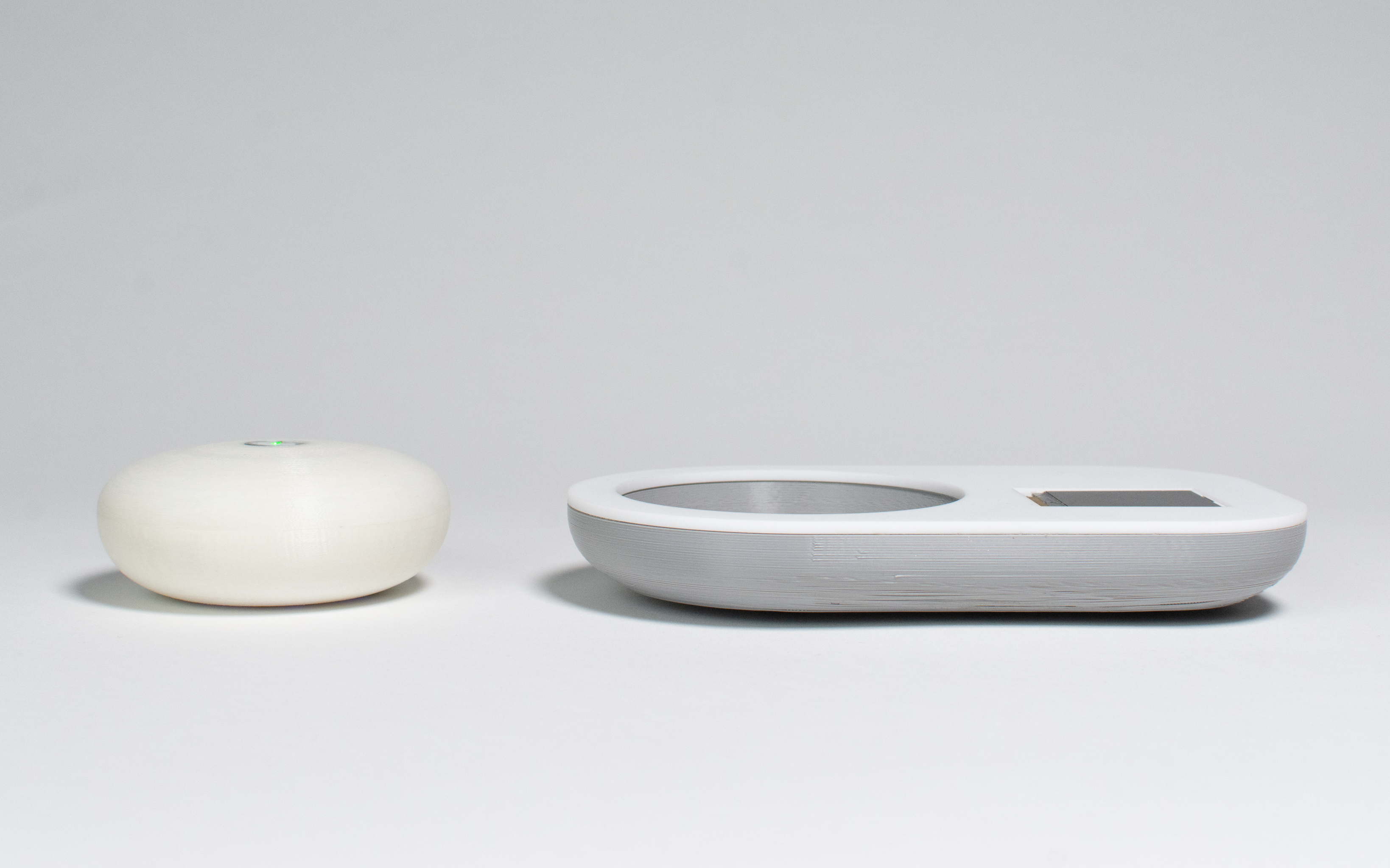
Fitting all the necessary components inside both enclosures proved a challenge, but was possible through careful modeling and prototyping.
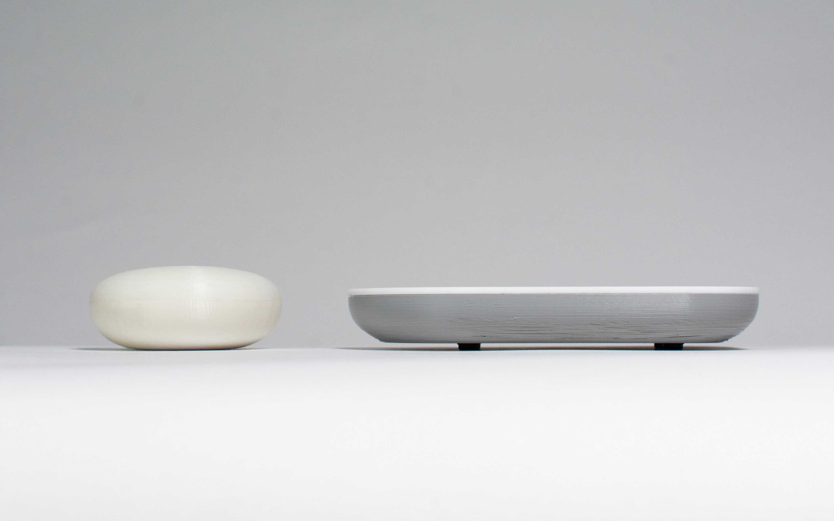
The puck measures about an inch and a half in height, meaning that the many parts inside had to be stacked and arranged carefully.
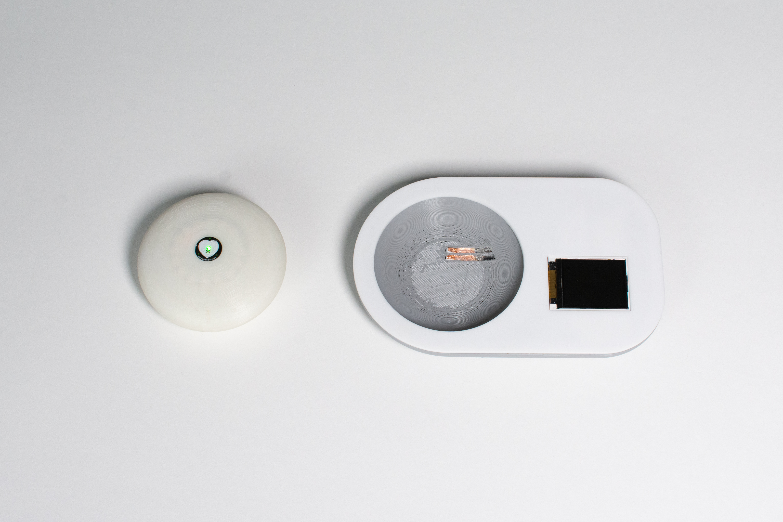
A pair of copper contacts on the dock provide omnidirectional charging to the battery inside the puck.
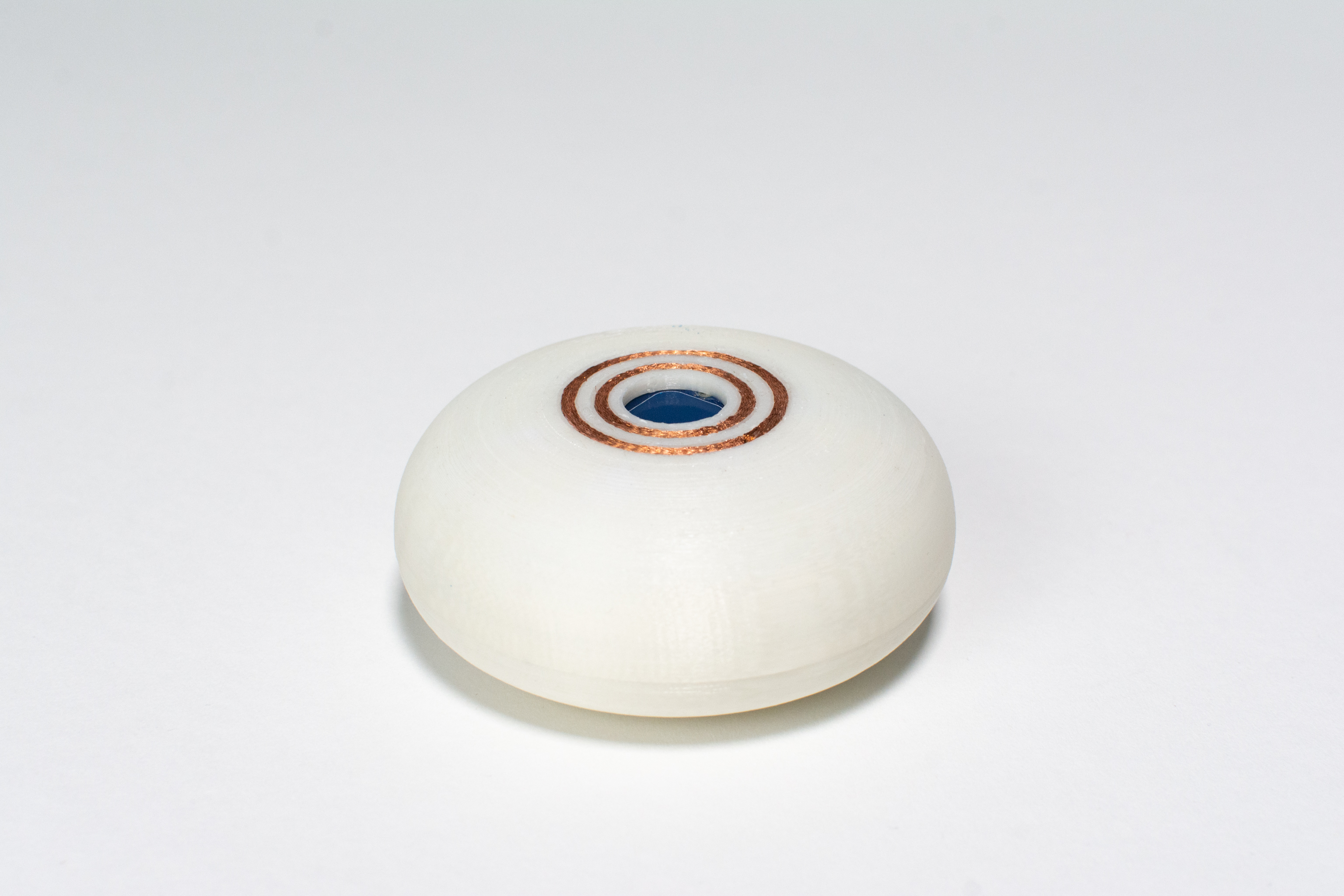
Two concentric rings surround the capacitive touch sensor. When Elinor returns home, she can simply drop the puck on the dock to start charging – no need to align contacts or plug in a cable.
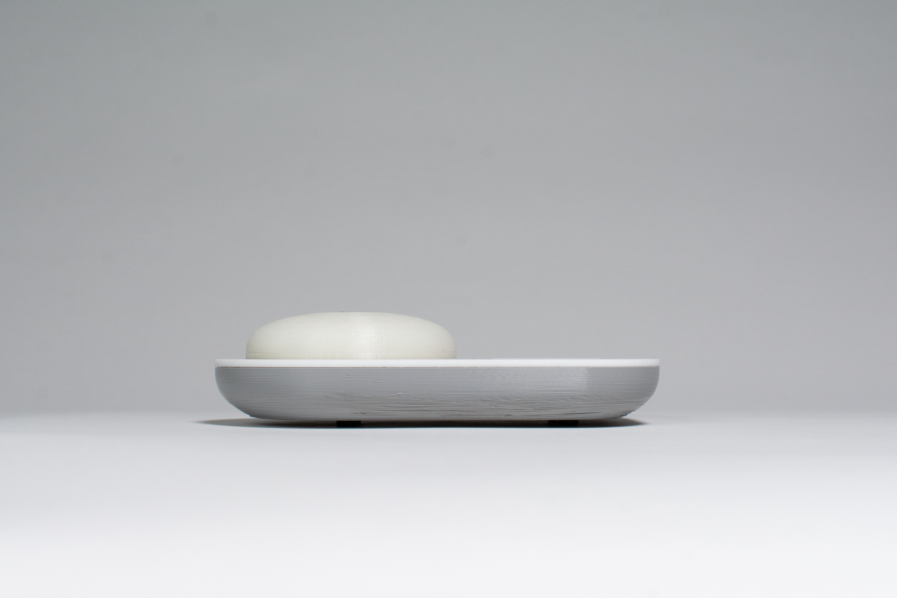
The puck charging on the dock.
Here’s how we imagine Elinor using our device:
Elinor wakes up in the morning and opens her calendar app on her phone to familiarise herself with the agenda for the day. The first thing she needs to do is drop her daughter off at school. Before leaving, she takes her mindfulness device with her and drops it in her bag.
After dropping her daughter off, she goes straight to a meeting and then to the grocery store. By the time she finishes grocery shopping, Elinor is feeling exhausted and has 5 minutes to spare before she needs to go back home. She takes out her mindfulness device and completes some deep breathing for 2 minutes while playing calming music on her meditative playlist, and feels so much more relaxed than she did before. She’s ready to go back home and tackle the rest of her day!
When she gets home, she decides she wants to do a few more breathing exercises. She sits at her desk where the dock for her mindfulness device is, and reads the instructions on the screen for 5 more minutes. Before going to sleep, she drops her mindfulness device in the dock that stays on her desk and it starts charging so it’s ready for her to use tomorrow.
When Elinor drops the puck onto the dock to charge, the display welcome her home and guides her through an optional meditation exercise.
How We Got Here
On the day of our final presentation and critique, we were really proud of how everything came together into a working device. Our last prototype is miles away from how our first prototype looked, and incorporated feedback from Elinor regarding features she wanted to see in our device as well as how she wanted it to look and feel.
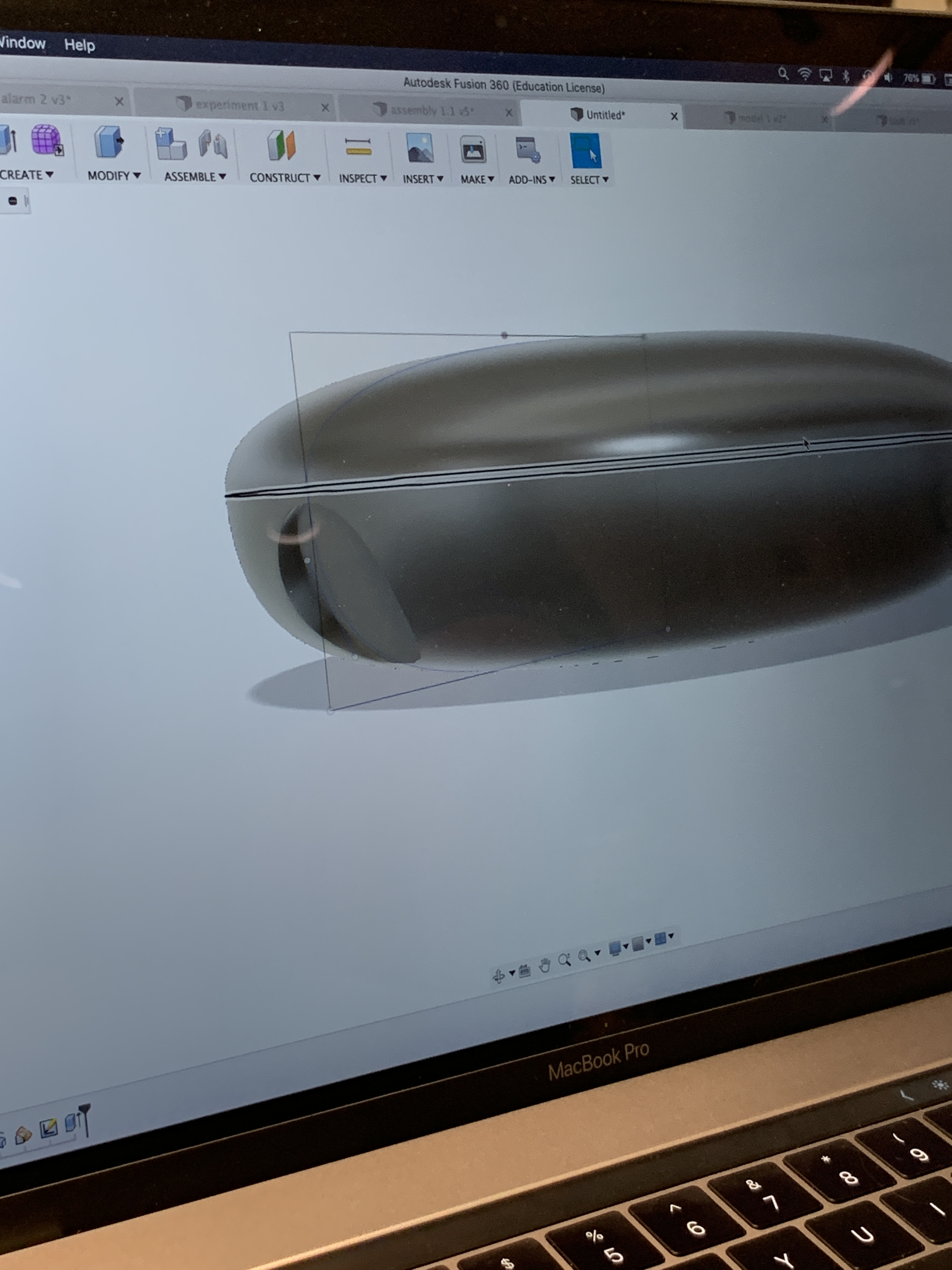
Starting to work on what our device would look like
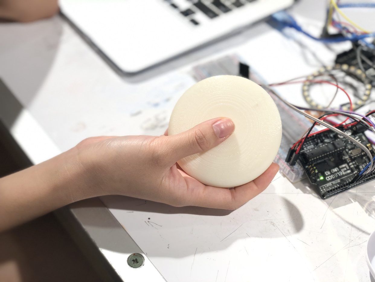
The first 3D print of a solid puck shape. We tested out the size of this one before moving on
One of our first considerations was the form factor of our portable device. Since Elinor will be using this device to help her through meditative exercises and to relax, it was important that the device itself evoked a sense of calmness. We were inspired by shapes like worry stones and organic forms such as a Google home that Elinor could easily hold in one hand while she uses it. We went through several different iterations of the form, starting with a compact puck looking shape and tested out the shape and size with Elinor before landing on the final form.
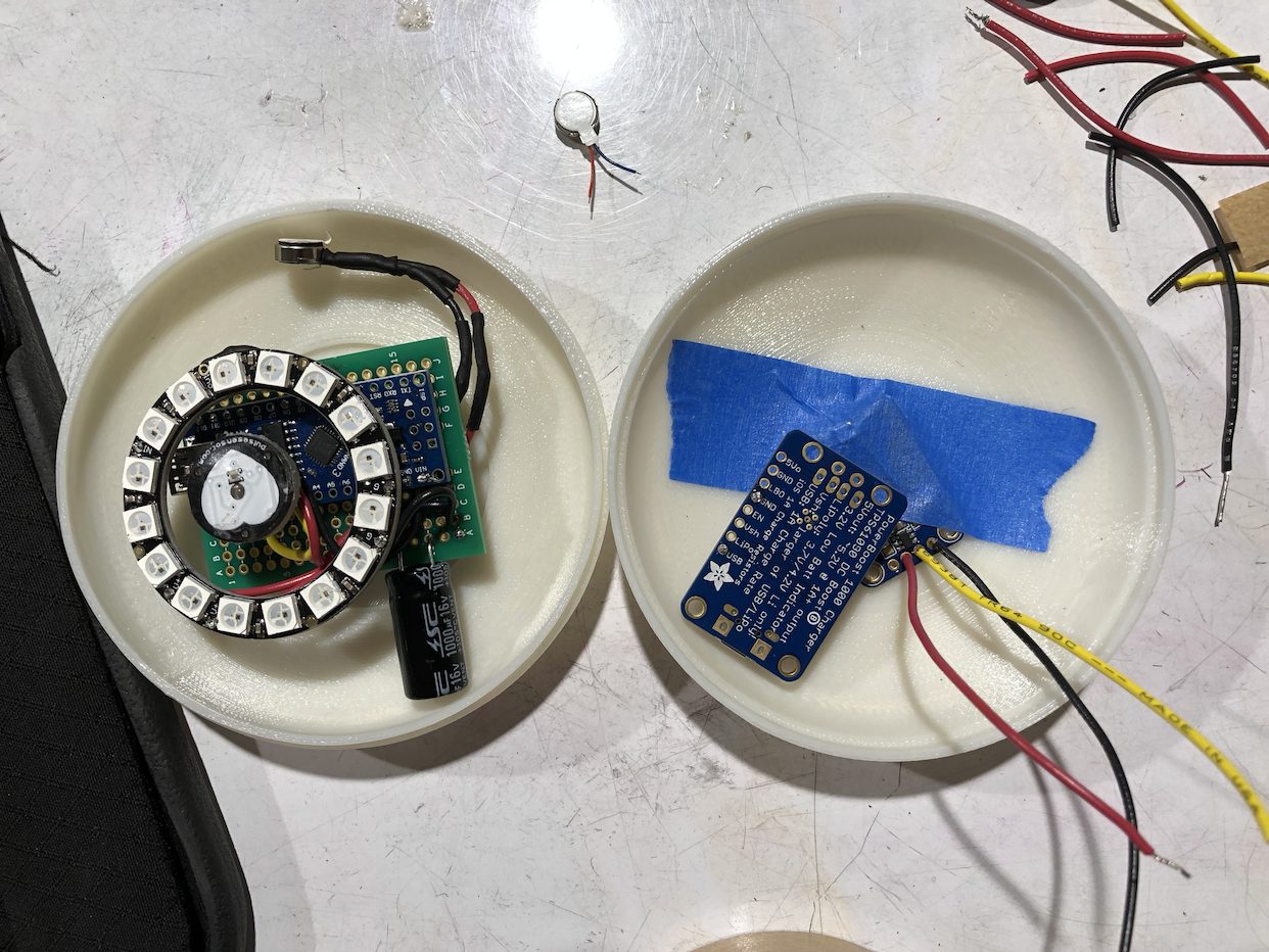
After testing with elinor’s hand, we landed on a size and also measured out our components to make sure everything fit inside
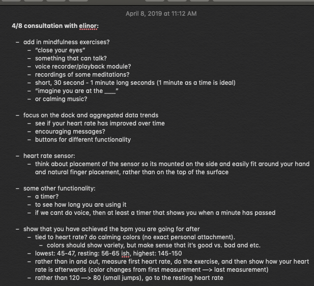
Notes from our consultation with Elinor after our first prototype
Elinor also provided a lot of inspiration for what types of features she wanted to see in our device. In the beginning, we intended on having an LED ring to visualise her heart rate through pulsing as well as a vibrating motor to provide haptic feedback. After meetings however, we learned that Elinor was less interested in features such as haptic feedback and was more interested in actually learning breathing/meditation exercises, so we created a playlist with calming sounds and guided breathing exercises as a companion and also added in an LCD screen in the dock that would teach her exercises and worked on building the most functionality in regard to the LED ring– such as changing colors. The pulsing started out with only basic white LEDs that corresponded with her heart rate. Elinor told us that she would love to see a variety of colors and that she would prefer colors other than white, so we used a light purple color for the first 5 seconds of usage while a baseline rate is being set, blue during the actual minute of deep breathing, and green to indicate when a minute has passed and the heart rate sensor turns off. We considered what types of colors would be most calming– we started out having red as the indication that a minute has passed, but decided it was too harsh and changed to red.
The idea for a one-minute timer also came from Elinor, who did not previously meditate or complete any type of breathing exercises during her lifestyle. She also did not want 5 or 10 minute long cycles because those are harder to fit into her schedule. As we hope our device can act as a sort of gateway into bringing more relaxation into her life, each breathing cycle is set at one minute at a time so that it’s something quick that can be done even while she is in her car.
We ran into many challenges along the way in regards to the electronic component of building our device. The heart rate sensor that was available to check out in our lab was a really finicky part and often displayed strange (too high or too low) heart rate readings when we used it (more details about the problems we ran into can be read here). We thought about going a different route and pivoting to use a different part or tackle the issue of mindfulness in a different way but ultimately decided to stick with it and order a new heart rate sensor that would hopefully work better. Fortunately, the new part that we ordered behaved much more normally and although far from medical grade, displayed normal and pretty accurate heart rate readings when compared with an apple watch.
Another issue we ran into was with the wireless data transmission. Initially, one of the features that we wanted to have was wireless data transmission from Elinor’s portable device to the dock that stayed at home to display average BPM and average usage amounts over the course of a day and over the course of a week. We worked really hard on implementing this feature and was able to make it work in the beginning stages, but when we went to put all of the parts together, we discovered that both devices needed to use the same specialised pin (the SPI pin) on the Arduino. We attempted to find workaround solutions and followed tutorials that had the same problem but ultimately was not able to fix the issue and decided to devote the rest of our time to making all of the other components of our final product work properly and look great.
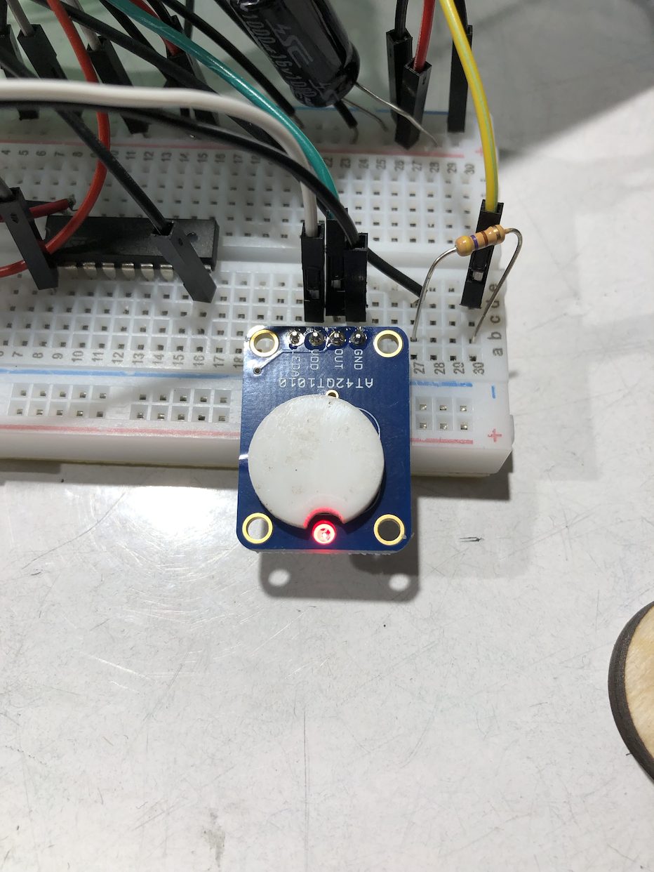
We added in a capacitative sensor that will turn on and off the device so that the heart rate sensor is not constantly measuring
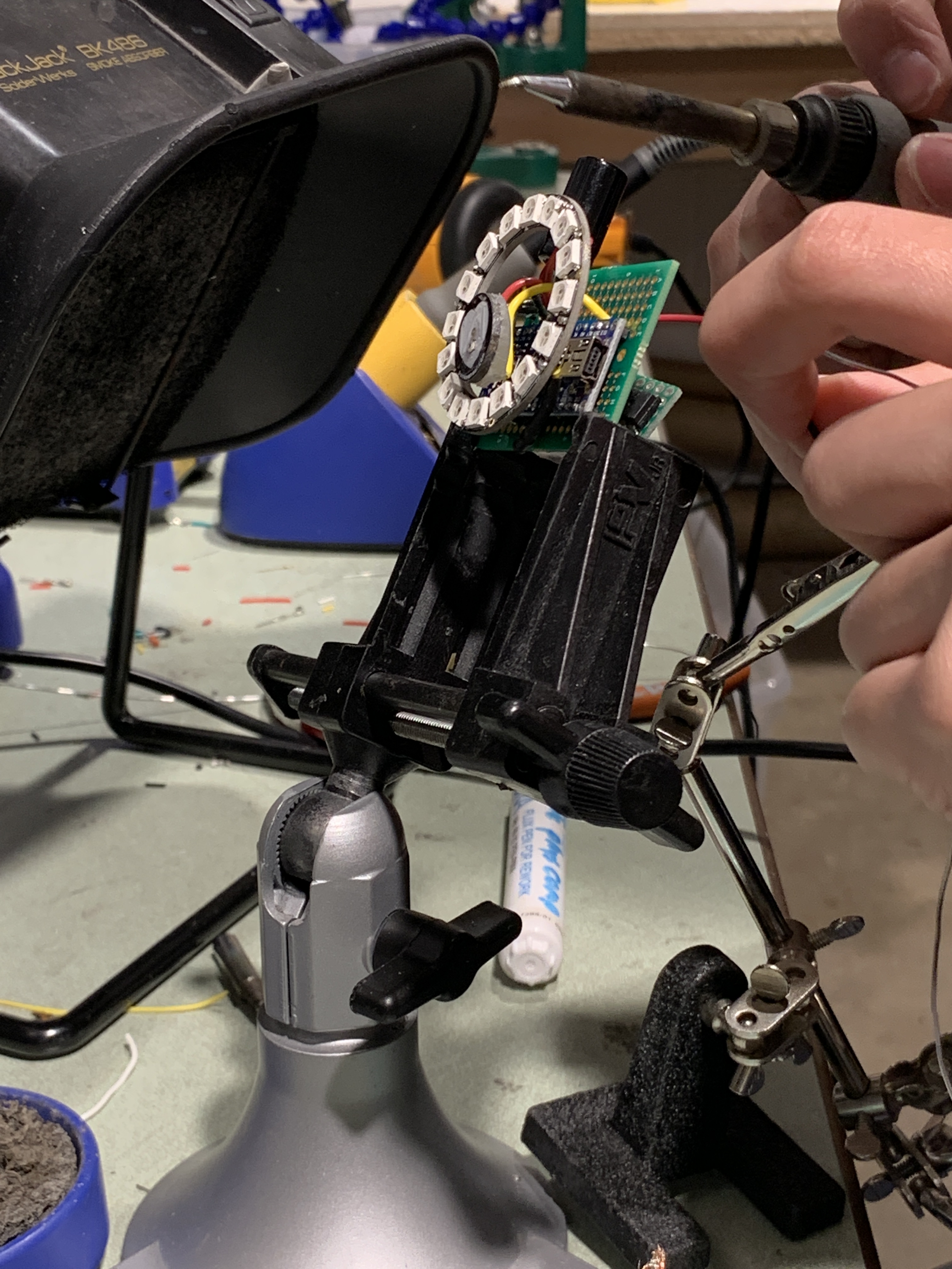
Soldering all of our components together to make them fit into our shell
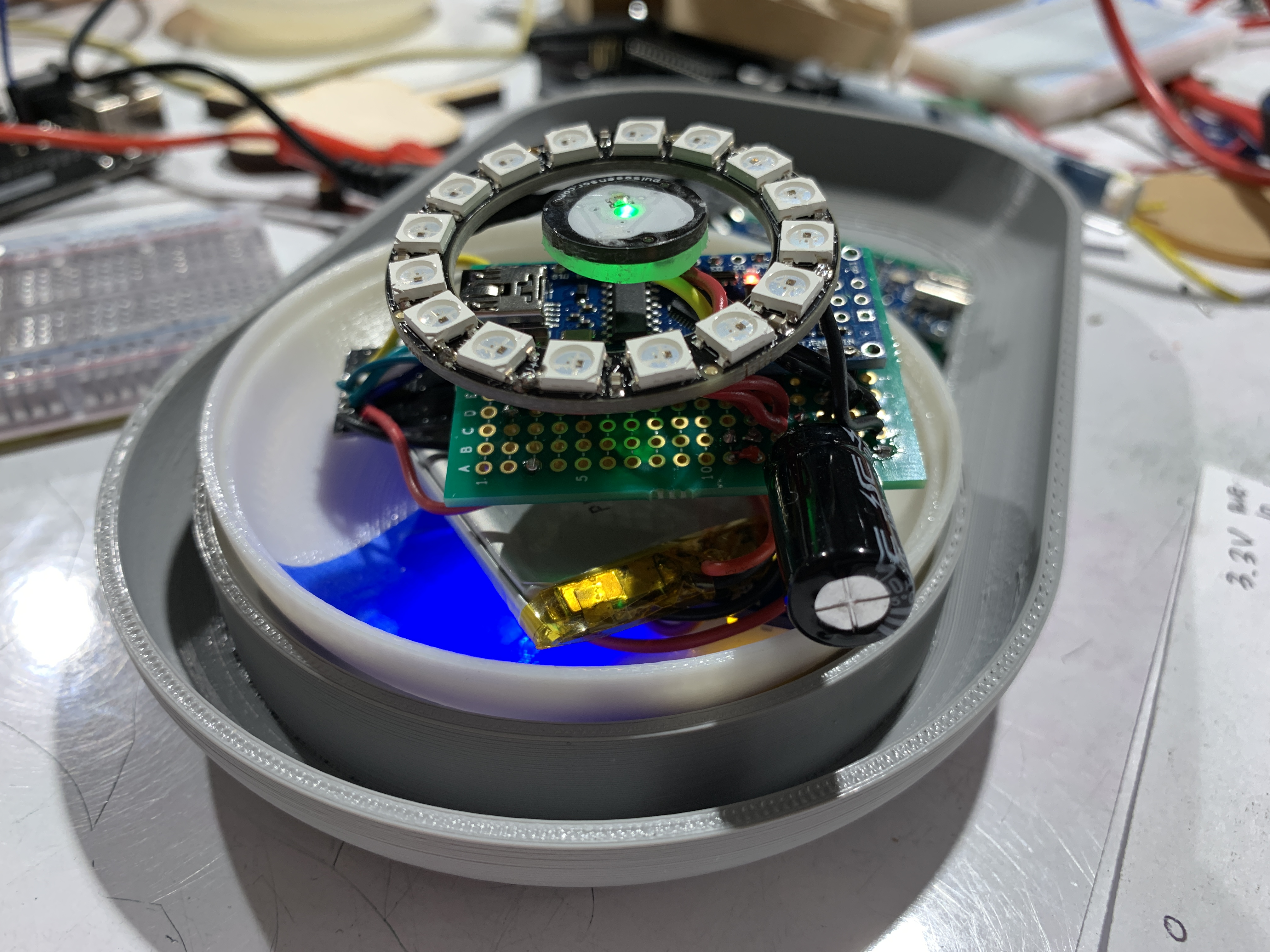
Making sure everything fits inside!
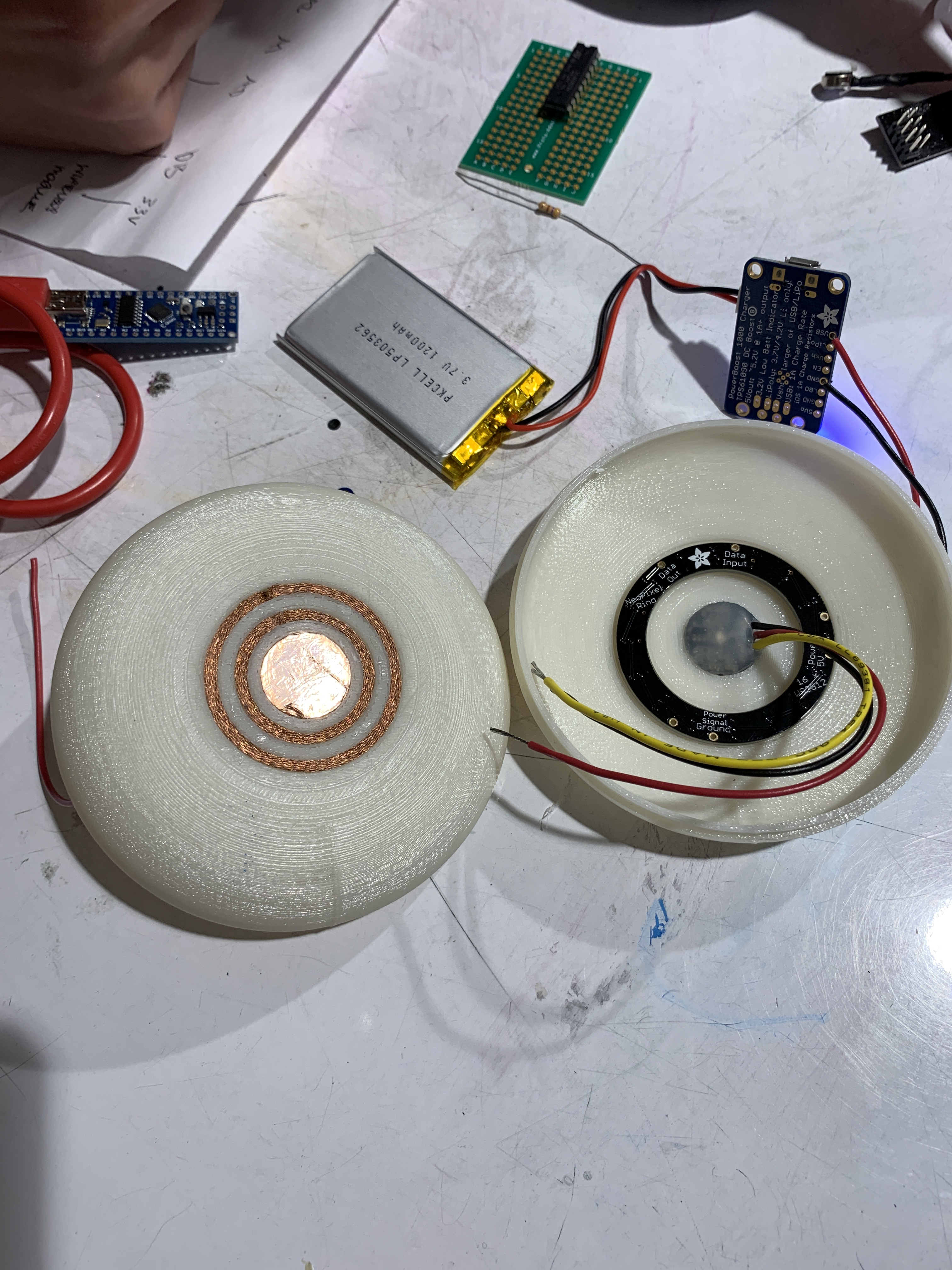
Working on the contacts to make sure the rechargeable battery works
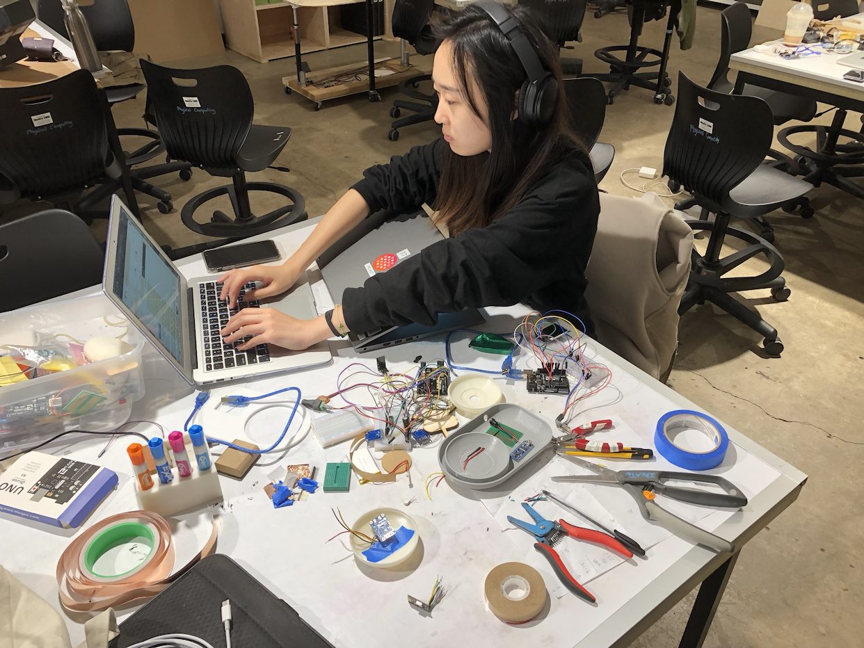
Working hard to debug and work with the mess of components on the 11th hour!
As most long-term projects go, we were initially able to stick to our schedule and plan as we worked individually on software and hardware. However, as we got closer to final critique day, we realised that fabrication and assembly of our products took much, much longer than we expected. The night before the critique we worked tirelessly to debug, solder, and assemble everything into a functioning beautiful device! The issues that we mentioned were by far our biggest problems but we wanted to make sure to deliver Elinor something that she would really appreciate.
Conclusions and Lessons Learned
At the critique, the positive feedback was largely directed at the form factor of the device and how polished it looked– “The design of the device is lovely. It looks very touchable and smooth.” “Nice design and good calming indicator.” We were really happy that visitors who came by and interacted with our device seemed to feel a sense of calmness from the device itself, which is what we had really hoped and intended for.
Recurring feedback that we received mostly revolved around if Elinor would actually use our device, and the necessity of it– “It depends on the user to create a habit.” “Doesn’t seem to solve a large problem.” Some future features we would want to add to address this sort of feedback would be to focus on data feedback between the portable device and the dock so that Elinor can take a look back at how many times she has used the device, and if her resting heart beat or average BPM has improved over the course of her usage. This would definitely be implemented in a second iteration of our project.
We also considered this “can’t she just use her phone?” factor throughout our design process, and made a conscious decision to keep our device as analog as possible. Elinor uses her digital phone, tablet, and watch very often and we wanted to create something more tactile and interactive that she can integrate into her daily life without feeling a huge sense of foreignness. The functionality exists on other devices, but the way that the features are presented is one of the most important parts.
In a future iteration, we would also definitely add more features for the portable component such as a different time length setting for the device so that Elinor can have 1, 3, 5, 10 minute settings. Some other, more physical features we would focus on if we had more time would be to refabricate the dock using a more sturdy print to make sure that it will stay on her desk without any issues or breakage.
Working with Elinor was a really unique experience that we had not been able to experience through a class or through any other project. At school we are constantly surrounded by like-minded people who often have similar life experiences. We had a great time visiting Elinor’s house and learning about the different perspectives that she has on life. This project also allowed for us to stretch our minds in terms of designing for her, since the prompt was really open-ended and let us work with an abstract problem like mindfulness.
We did feel a bit of a disadvantage as a two-person team, since one of us almost solely focused on software and the other on hardware. If we had one more person, we feel that we would have been able to add more functionality than we were able to, or spend even more time honing in on the form factor. Despite this, we are really proud of what we were able to create and learned a lot not just about electronics, but about working with people who are different from us! Watching Elinor use our device on final critique day was definitely the highlight of the project.
Schematic:
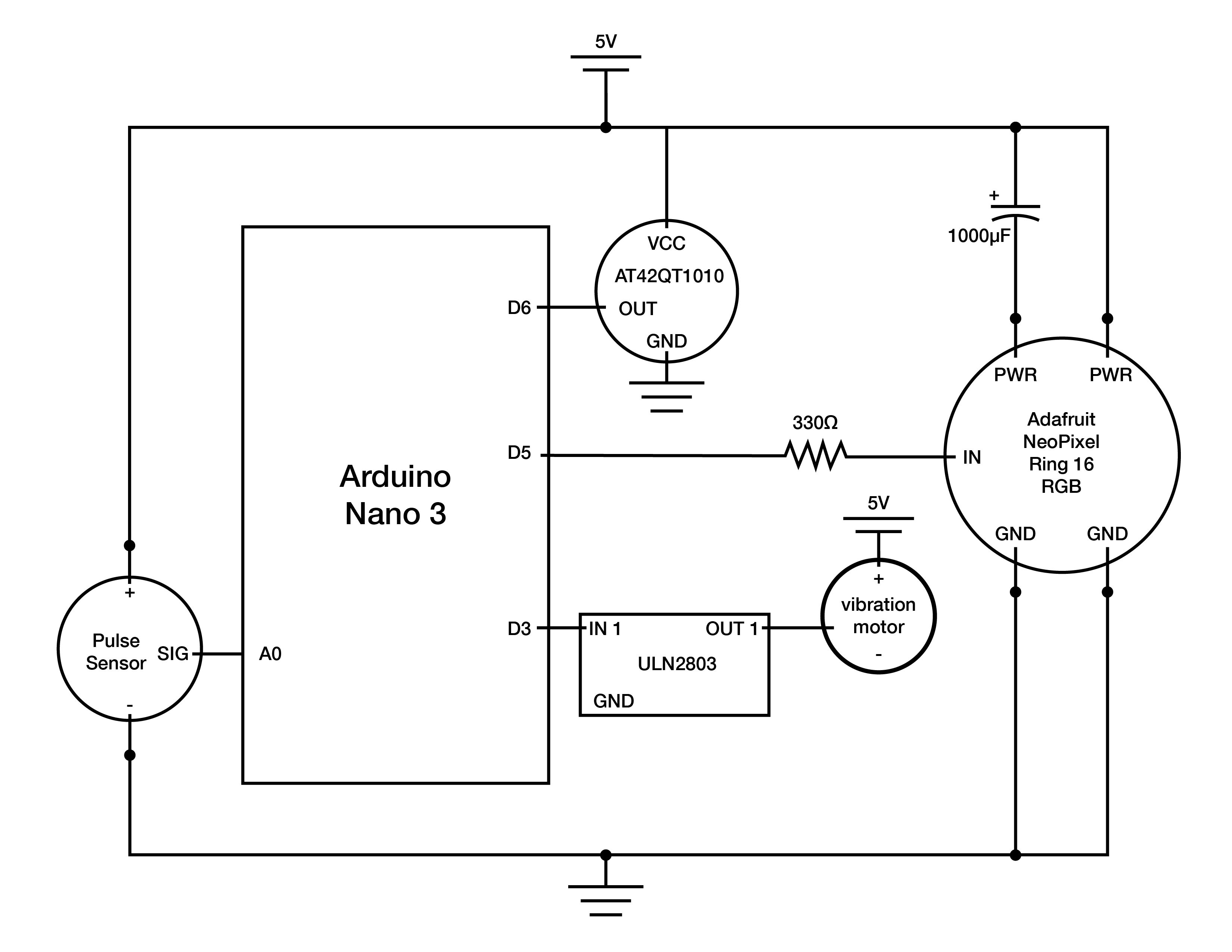
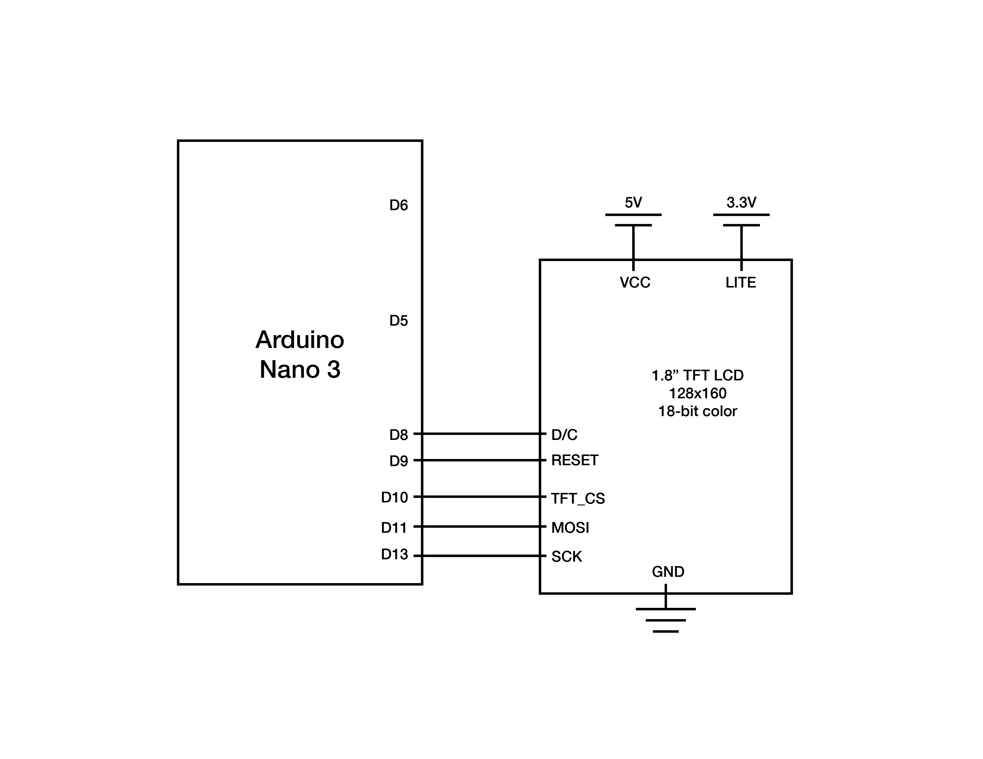
Code for the portable device:
/*
 *  Mindfulness Device
 *
 *  Karen Kim + Ian Shei
 *
 *  This code uses a pulse sensor to measure heart rate
 *  and display it through an LED ring. There are
 *  different thresholds that determine the speed
 *  of the pulsing of the LED ring.
 *
 *  Input: heart rate sensor (A0), capacitative sensor (Pin 6)
 *  Output: LED ring (Pin 5)
 *
 *  Example code used from:
   http://pulsesensor.com/pages/pulse-sensor-amped-arduino-v1dot1
   Version 1.0 by Mike Barela for Adafruit Industries, Fall 2015
*/

#include <Adafruit_NeoPixel.h>    // Library containing
#include <SPI.h>
#include <nRF24L01.h>
#include <RF24.h>

#define CE_PIN   9
#define CSN_PIN 10

// Behavior setting variables
int pulsePin = A0;                 // Pulse Sensor purple wire connected to analog pin 0
int blinkPin = 13;                // Digital pin to blink led at each beat
int ringPin  = 5;                 // pin to do fancy neopixel effects at each beat
int fadeRate = 0;                 // used to fade LED on with PWM on ringPin
int sensorPin = 6;
const int motorPin = 3;

// array for LED brightness pulsing values
int brightnessVal [201] = {0, 0, 0, 1, 1, 2, 2, 3, 4, 5, 6, 8, 9, 10, 12, 14, 16, 18, 20, 22, 24, 27, 29, 32, 35, 37, 40, 43, 46, 49, 53, 56, 59, 63, 66, 70, 73, 77, 81, 84, 88, 92, 96, 100, 104, 108, 112, 116, 119, 123, 128, 132, 136, 139, 143, 147, 151, 155, 159, 163, 167, 171, 174, 178, 182, 185, 189, 192, 196, 199, 202, 206, 209, 212, 215, 218, 220, 223, 226, 228, 231, 233, 235, 237, 239, 241, 243, 245, 246, 247, 249, 250, 251, 252, 253, 253, 254, 254, 255, 255, 255, 255, 255, 254, 254, 253, 253, 252, 251, 250, 249, 247, 246, 245, 243, 241, 239, 237, 235, 233, 231, 228, 226, 223, 220, 218, 215, 212, 209, 206, 202, 199, 196, 192, 189, 185, 182, 178, 174, 171, 167, 163, 159, 155, 151, 147, 143, 139, 136, 132, 128, 123, 119, 116, 112, 108, 104, 100, 96, 92, 88, 84, 81, 77, 73, 70, 66, 63, 59, 56, 53, 49, 46, 43, 40, 37, 35, 32, 29, 27, 24, 22, 20, 18, 16, 14, 12, 10, 9, 8, 6, 5, 4, 3, 2, 2, 1, 1, 0, 0, 0};

const byte slaveAddress[5] = {'R','x','A','A','A'}; // for radio
RF24 radio(CE_PIN, CSN_PIN); // Create a Radio

char message[10]; // array length for radio message
char txNum = '0';

unsigned long currentMillis;
unsigned long prevMillis;
unsigned long txIntervalMillis = 1000; // send once per second


// these variables are volatile because they are used during the interrupt service routine
volatile int BPM;                   // used to hold the pulse rate
volatile int Signal;                // holds the incoming raw data
volatile int IBI = 600;             // holds the time between beats, the Inter-Beat Interval
volatile boolean Pulse = false;     // true when pulse wave is high, false when it's low
volatile boolean QS = false;        // becomes true when Arduoino finds a beat.

// Set up use of NeoPixels
const int NUMPIXELS = 24;           // Put the number of NeoPixels you are using here
const int BRIGHTNESS = 60;          // Set brightness of NeoPixels here
Adafruit_NeoPixel strip = Adafruit_NeoPixel(24, ringPin, NEO_GRBW + NEO_KHZ800);

unsigned long startMillis;
bool inTrial = false;
bool inWait = false;
bool turnOn = false;

int bpmCount = 0;
int bpmAvg = 0;
int totalBPM = 0;
int dailyBPM[10] = {-1,-1,-1,-1,-1,-1,-1,-1,-1,-1};

void setup(){
  pinMode(blinkPin,OUTPUT);         // pin that will blink to your heartbeat!
  pinMode(motorPin, OUTPUT);
  pinMode(sensorPin, INPUT);
  Serial.begin(9600);           // Serial output data for debugging or external use
  strip.begin();
  strip.setBrightness(BRIGHTNESS);
  for (int x=0; x < NUMPIXELS; x++) {  // Initialize all pixels to 'off'
     strip.setPixelColor(x, strip.Color(0, 0, 0));
  }
  strip.show();                     // Ensure the pixels are off
  delay(1000);                      // Wait a second
  interruptSetup();                 // sets up to read Pulse Sensor signal every 2mS

   radio.begin();
   radio.setDataRate( RF24_250KBPS );
   radio.setRetries(3,5); // delay, count
   radio.openWritingPipe(slaveAddress);
}

void loop(){
  int sensorRead = digitalRead(sensorPin);
  // Serial.println(sensorRead);

  if (sensorRead == HIGH){ // use capaacitative sensor to turn on device
    turnOn = true;
  }

  if (turnOn == true){
  if (inWait == false and inTrial == false and QS == true){  // Quantified Self flag is true when arduino finds a heartbeat
//    analogWrite(motorPin, 100);
     Serial.println("START WAIT"); // setting 5 second baseline for heartrate
     inWait = true;
//     inTrial = true;
     startMillis = millis();
//     fadeRate = 255;                  // Set 'fadeRate' Variable to 255 to fade LED with pulse
     Serial.println(BPM);
//     sendDataSerial('B',BPM);       // send heart rate with a 'B' prefix
//     sendDataSerial('Q',IBI);       // send time between beats with a 'Q' prefix
     QS = false;                      // reset the Quantified Self flag for next time
  }

  else if (inWait == true and millis() - startMillis >= 5000){
      Serial.println("END WAIT");

      inTrial = true;
      inWait = false;
      startMillis = millis();
    }

  else if (inTrial == true and QS == true){
    bpmAvg = totalBPM/bpmCount;
//    Serial.println(bpmAvg);
    Serial.println("IN TRIAL");
//    Serial.println(millis() - startMillis);

    if (millis() - startMillis >= 5000){
      Serial.println("END OF TRIAL");
      inTrial = false;
      for (int x=0; x < NUMPIXELS; x++) {  // Initialize all pixels to 'off'
        strip.setPixelColor(x, strip.Color(255, 0, 0)); // blue light for during 1 minute cycle
      }
      strip.show();
      send(bpmAvg);
      totalBPM=0;
      bpmCount=0;
      delay(1000);
      turnOn = false;
    }
 //   fadeRate = 400;
    QS = false;
  }

  if (inTrial == true){
    Serial.print("BPM=");
    Serial.println(BPM);
    totalBPM+=BPM;
    bpmCount+=1;
    ledFadeToBeat(BPM);                    // Routine that fades color intensity to the beat
  }

  else if (inWait == true) {
    for (int x=0; x < NUMPIXELS; x++) {  // Initialize all pixels to 'off'
      strip.setPixelColor(x, strip.Color(0, 255, 0)); // turns off after 1 minute
      }
      strip.show();
  }

  else {
    setStrip(255,0,0,BPM);
    delay(3000);
  }
  delay(100);                          //  take a break
}
}

void ledFadeToBeat(int BPM) {
  static int i = 100;
           // Set LED fade value
  if (BPM < 50){
    i+=1;
      if (i >= 201) {
        i = 0;
    }
    fadeRate = brightnessVal[i];
    fadeRate = constrain(fadeRate,0,255);   // Keep LED fade value from going into negative numbers
    setStrip(0,0,fadeRate, BPM);
  }
  else if (BPM >= 50 and BPM < 80){ // setting BPM thresholds to set pulsing speed
    i+=2;
    if (i >= 201) {
       i = 0;
    }
    fadeRate = brightnessVal[i];
    fadeRate = constrain(fadeRate,0,255);   // Keep LED fade value from going into negative numbers
    setStrip(0,0,fadeRate, BPM);
  }
  else if (BPM >= 80 and BPM < 100){
    i+=3;
    if (i >= 201) {
       i = 0;
    }
    fadeRate = brightnessVal[i];
    fadeRate = constrain(fadeRate,0,255);   // Keep LED fade value from going into negative numbers
    setStrip(0,0,fadeRate, BPM);
  }
  else if (BPM >= 100 and BPM < 120){
    i+=4;
    if (i >= 201) {
       i = 0;
    }
    fadeRate = brightnessVal[i];
    fadeRate = constrain(fadeRate,0,255);   // Keep LED fade value from going into negative numbers
    setStrip(0,0,fadeRate, BPM);
  }
  else if (BPM >= 120 and BPM < 150){
    i+=5;
    if (i >= 201) {
       i = 0;
    }
    fadeRate = brightnessVal[i];
    fadeRate = constrain(fadeRate,0,255);   // Keep LED fade value from going into negative numbers
    setStrip(0,0,fadeRate, BPM);
  }
  else{
    for (int x=0; x < NUMPIXELS; x++) {  // Initialize all pixels to 'off'
       strip.setPixelColor(x, strip.Color(0, 0, 0));
    }
    strip.show();
    i=0;
  }
//  Serial.print("i=");
//  Serial.println(i);
//    sendDataSerial('R',fadeRate);
}

void sendDataSerial(char symbol, int data ) {
//    Serial.print(symbol);                // symbol prefix tells Processing what type of data is coming
//    Serial.println(data);                // the data to send culminating in a carriage return
}

void setStrip(int r, int g, int b, int BPM) {     // Set the strip to one color intensity (blue)
  for (int x=0; x < NUMPIXELS; x++) {
    strip.setPixelColor(x, strip.Color(0, 0, b));
  }
   strip.show();
}

/*
  sending the 10 most recent bpm values to receiver

*/
void send(int bpmAvg) { // function for radio

  // shift every BPM value to the right for the new bpmAvg
  for (int i=0; i<9; i++){
    dailyBPM[i+1] = dailyBPM[i];
  }
  dailyBPM[0] = bpmAvg; //putting newest bpmAvg value at the front of array

  bool rslt = radio.write( &dailyBPM, sizeof(dailyBPM) );
        // Always use sizeof() as it gives the size as the number of bytes.
        // For example if dataToSend was an int sizeof() would correctly return 2

    Serial.print("Data Sent ");
    for (int x = 0; x < (sizeof(dailyBPM) / sizeof(dailyBPM[0])); x++) {
      Serial.println(dailyBPM[x]);
    }
    if (rslt) {
        Serial.println("  Acknowledge received");
        memset(dailyBPM, -1, sizeof(dailyBPM));

        // for (int x = 0; x < sizeof(dailyBPM) / sizeof(dailyBPM[0]); x++)
        // updateMessage();
    }

    else {
        Serial.println("  Tx failed");
    }
}
Code for the dock:
#include <Adafruit_GFX.h>    // Core graphics library
#include <Adafruit_ST7735.h> // Hardware-specific library for ST7735
#include <Adafruit_ST7789.h> // Hardware-specific library for ST7789
#include <SPI.h>


#ifdef ADAFRUIT_HALLOWING
  #define TFT_CS        39 // Hallowing display control pins: chip select
  #define TFT_RST       37 // Display reset
  #define TFT_DC        38 // Display data/command select
  #define TFT_BACKLIGHT  7 // Display backlight pin
#else

  #define TFT_CS        10
  #define TFT_RST        9 // Or set to -1 and connect to Arduino RESET pin
  #define TFT_DC         8
#endif

Adafruit_ST7735 tft = Adafruit_ST7735(TFT_CS, TFT_DC, TFT_RST);

const int CHARGE_PIN1 = A1; // display turns on when contact is made from the device to the dock
const int CHARGE_PIN2 = A2;
const int CHARGE_TOLERANCE = 20;


void setup(void) {
#ifdef ADAFRUIT_HALLOWING
  tft.initR(INITR_HALLOWING);        // Initialize HalloWing-oriented screen
  pinMode(TFT_BACKLIGHT, OUTPUT);
  digitalWrite(TFT_BACKLIGHT, HIGH); // Backlight on
#else
  // Use this initializer if using a 1.8" TFT screen:
  tft.initR(INITR_BLACKTAB);      // Init ST7735S chip, black tab
#endif

  tft.setRotation(1); // rotate the screen to horizontal
  pinMode(CHARGE_PIN1, INPUT);
  pinMode(CHARGE_PIN2, INPUT);
  Serial.begin(9600);

  testfillcircles(10, ST77XX_BLUE);
  testdrawcircles(10, ST77XX_WHITE);
}

void loop() {
  static bool plugged = false;
  int chargeRead1 = analogRead(CHARGE_PIN1); // reading if contact has been made
  int chargeRead2 = analogRead(CHARGE_PIN2);
//  Serial.println(chargeRead1);
//  Serial.println(chargeRead2);

  if ((chargeRead1 - CHARGE_TOLERANCE <= chargeRead2) and  // portable device not plugged in
    (chargeRead2 <= chargeRead1 + CHARGE_TOLERANCE)) {
      plugged = false;
      tft.fillScreen(ST77XX_BLACK);
     }

  else if (plugged == false) { // this condition fires once we plug in
    tftPrintTest();
    plugged = true; // portable device marked as "plugged in" now
}

  delay(500);
}


void tftPrintTest() { // the content of the screens
  tft.fillScreen(ST77XX_MAGENTA);
  tft.setTextColor(ST77XX_WHITE);
  tft.setCursor(0, 30);
  tft.setTextSize(3);
  tft.println("WELCOME");
  tft.setCursor(0, 60);
  tft.println("HOME");
  tft.setCursor(0, 90);
  tft.println("ELINOR!");
  delay(3000);
  tft.setTextSize(1);
  tft.setCursor(0, 20);
  tft.fillScreen(ST77XX_BLACK);
  tft.setTextColor(ST77XX_WHITE);
  tft.println("Hello Elinor!");
  tft.setCursor(0, 40);
  tft.println("Hope you are having");
  tft.setCursor(0, 60);
  tft.println("a great day.");
  delay(5000);
  tft.fillScreen(ST77XX_BLUE);
  tft.setTextColor(ST77XX_WHITE);
  tft.setCursor(0, 10);
  tft.setTextSize(2);
  tft.println("Here are some");
  tft.setCursor(0, 30);
  tft.println("breathing");
  tft.setCursor(0, 50);
  tft.println("tips for you!");
  delay(3000);
  tft.fillScreen(ST77XX_BLUE);
  tft.setTextColor(ST77XX_WHITE);
  tft.setCursor(0, 10);
  tft.setTextSize(2);
  tft.println("First, take a");
  tft.setCursor(0, 30);
  tft.println("long, slow");
  tft.setCursor(0, 55);
  tft.println("INHALE.");
  delay(3000);
  tft.fillScreen(ST77XX_BLUE);
  tft.setTextColor(ST77XX_WHITE);
  tft.setCursor(0, 10);
  tft.setTextSize(2);
  tft.println("Next, a quick");
  tft.setCursor(0, 30);
  tft.println("and powerful");
  tft.setCursor(0, 55);
  tft.println("EXHALE.");
  delay(3000);
  tft.fillScreen(ST77XX_BLUE);
  tft.setTextColor(ST77XX_WHITE);
  tft.setCursor(0, 10);
  tft.println("Take a total");
  tft.setCursor(0, 30);
  tft.println("of 10 breaths");
  delay(3000);
  tft.fillScreen(ST77XX_WHITE);
  testfillcircles(10, ST77XX_BLUE);
  testdrawcircles(10, ST77XX_WHITE);
  delay(4000);
  testlines(ST77XX_YELLOW);
  delay(2000);
  testfastlines(ST77XX_RED, ST77XX_BLUE);
  delay(2000);
  tft.fillScreen(ST77XX_GREEN);
  tft.setTextColor(ST77XX_WHITE);
  tft.setCursor(0, 10);
  tft.setTextSize(2);
  tft.println("Here's a");
  tft.setCursor(0, 30);
  tft.println("tip for you!");
  delay(3000);
  tft.fillScreen(ST77XX_GREEN);
  tft.setTextColor(ST77XX_WHITE);
  tft.setCursor(0, 10);
  tft.setTextSize(2);
  tft.println("Deep breaths");
  tft.setCursor(0, 30);
  tft.println("increase your");
  tft.setCursor(0, 50);
  tft.println("oxygen flow.");
  delay(2000);
  tft.fillScreen(ST77XX_GREEN);
  tft.setTextColor(ST77XX_WHITE);
  tft.setCursor(0, 10);
  tft.setTextSize(2);
  tft.println("Also, it");
  tft.setCursor(0, 30);
  tft.println("promotes a");
  tft.setCursor(0, 50);
  tft.println("state of");
  tft.setCursor(0, 70);
  tft.println("CALMNESS.");
  delay(5000);
  tft.fillScreen(ST77XX_WHITE);
  testfillcircles(10, ST77XX_BLUE);
  testdrawcircles(10, ST77XX_WHITE);
}

void testfillcircles(uint8_t radius, uint16_t color) { //graphics for elinor to view while breathing
  for (int16_t x=radius; x < tft.width(); x+=radius*2) {
    for (int16_t y=radius; y < tft.height(); y+=radius*2) {
      tft.fillCircle(x, y, radius, color);
    }
  }
}

void testdrawcircles(uint8_t radius, uint16_t color) {
  for (int16_t x=0; x < tft.width()+radius; x+=radius*2) {
    for (int16_t y=0; y < tft.height()+radius; y+=radius*2) {
      tft.drawCircle(x, y, radius, color);
    }
  }
}

void testlines(uint16_t color) {
  tft.fillScreen(ST77XX_BLACK);
  for (int16_t x=0; x < tft.width(); x+=6) {
    tft.drawLine(0, 0, x, tft.height()-1, color);
    delay(0);
  }
  for (int16_t y=0; y < tft.height(); y+=6) {
    tft.drawLine(0, 0, tft.width()-1, y, color);
    delay(0);
  }

  tft.fillScreen(ST77XX_BLACK);
  for (int16_t x=0; x < tft.width(); x+=6) {
    tft.drawLine(tft.width()-1, 0, x, tft.height()-1, color);
    delay(0);
  }
  for (int16_t y=0; y < tft.height(); y+=6) {
    tft.drawLine(tft.width()-1, 0, 0, y, color);
    delay(0);
  }

  tft.fillScreen(ST77XX_BLACK);
  for (int16_t x=0; x < tft.width(); x+=6) {
    tft.drawLine(0, tft.height()-1, x, 0, color);
    delay(0);
  }
  for (int16_t y=0; y < tft.height(); y+=6) {
    tft.drawLine(0, tft.height()-1, tft.width()-1, y, color);
    delay(0);
  }

  tft.fillScreen(ST77XX_BLACK);
  for (int16_t x=0; x < tft.width(); x+=6) {
    tft.drawLine(tft.width()-1, tft.height()-1, x, 0, color);
    delay(0);
  }
  for (int16_t y=0; y < tft.height(); y+=6) {
    tft.drawLine(tft.width()-1, tft.height()-1, 0, y, color);
    delay(0);
  }
}

void testfastlines(uint16_t color1, uint16_t color2) {
  tft.fillScreen(ST77XX_BLACK);
    for (int16_t y=0; y < tft.height(); y+=5) {
      tft.drawFastHLine(0, y, tft.width(), color1);
      }
    for (int16_t x=0; x < tft.width(); x+=5) {
      tft.drawFastVLine(x, 0, tft.height(), color2);
      }
}
3D fabrication files:
]]>After meeting with Elinor, we decided that we wanted to make her a device that helps her focus on her mindfulness and encourage her to take some breaks during her busy schedule. The prototype that we built synchronises heart rate monitor readings with an LED ring and a vibrating motor to help Elinor visualise her current state and bring her back down to her resting heart rate.
PROTOTYPE
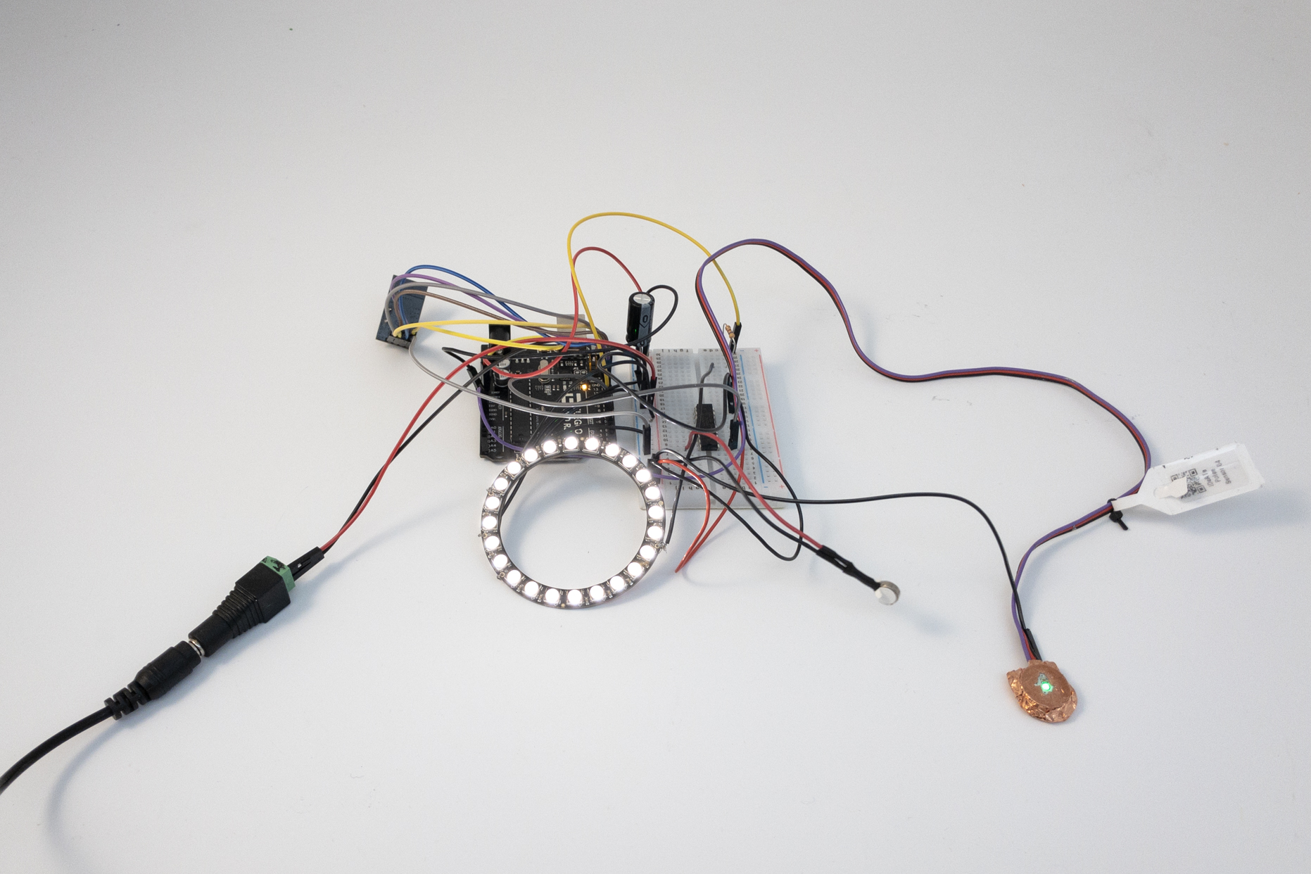
The development/testing setup with components plugged in to a breadboard. Included are a pulse oximeter, vibration motor, LED ring, and wireless communication module.
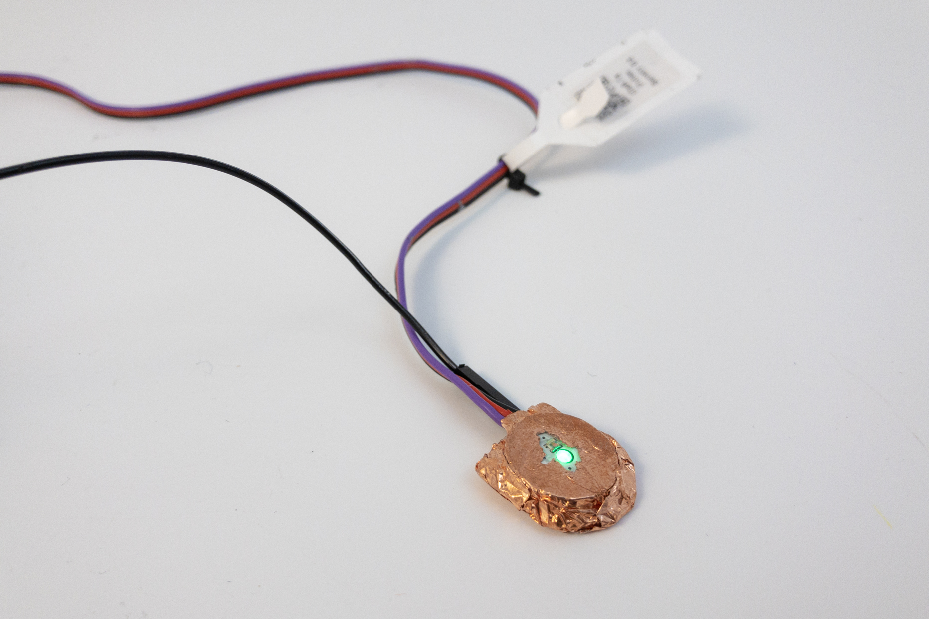
The pulse oximeter (called a “Pulse Sensor Amped”) exhibited large amounts of interference, particularly around moving metal objects. We tried creating a Faraday cage around the part to shield it from such effects, but success was limited.
PROCESS
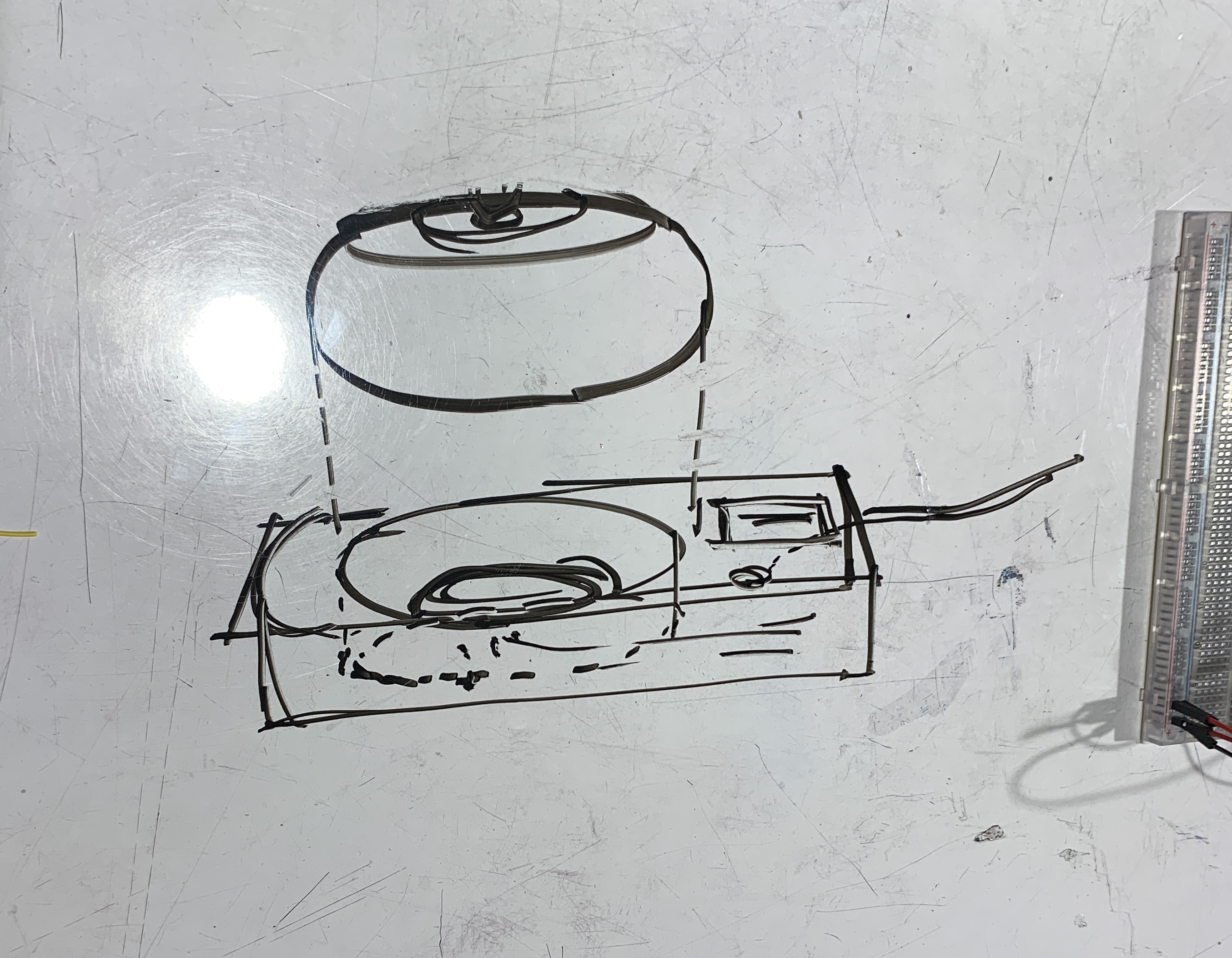
A sketch of how we envision our device: a portable pebble-like device EIinor can take on the go, that has a dock where she can charge it and see historical data related to her heart rates.
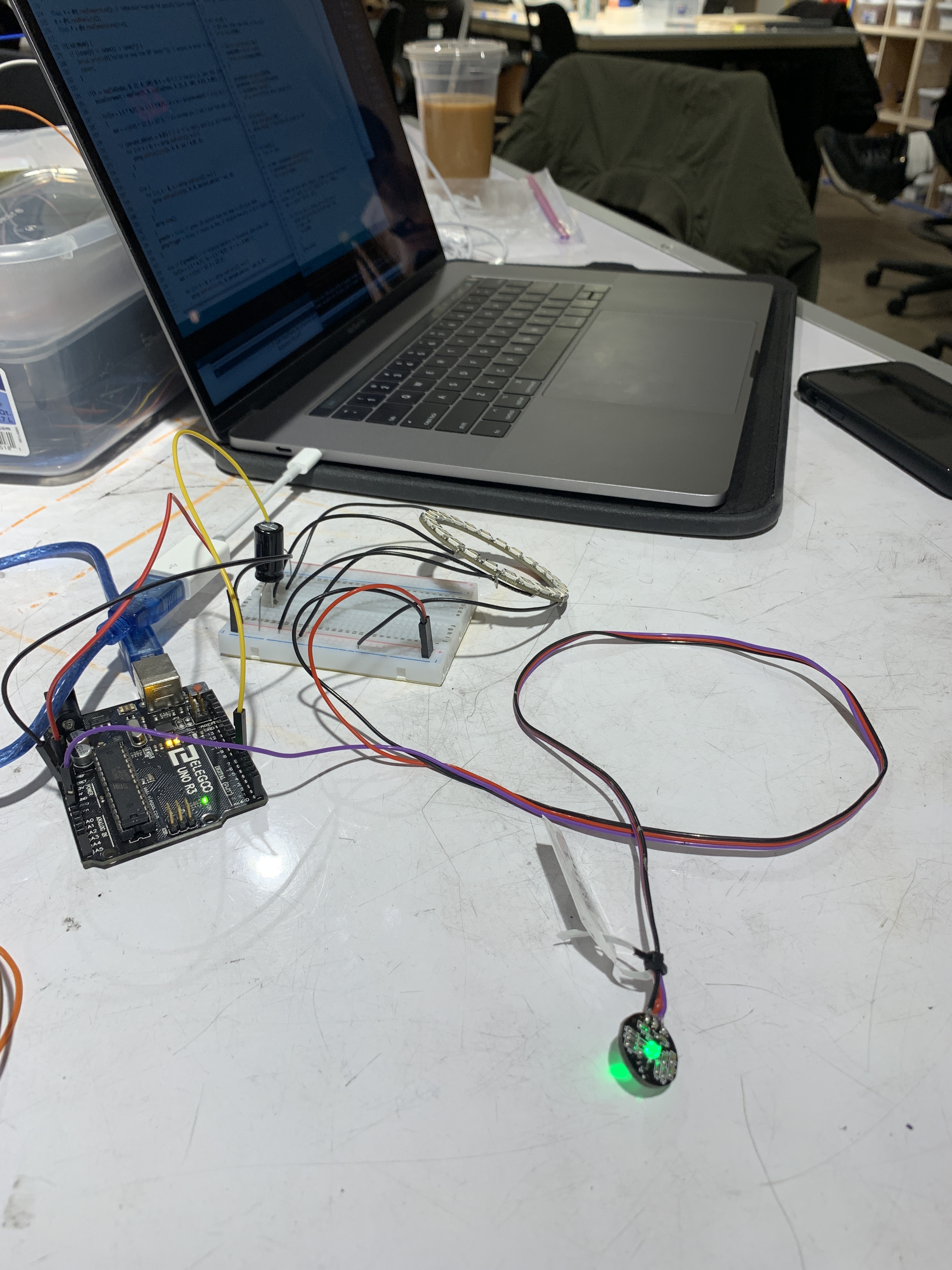
The first electronics part we tackled was the heart rate monitor and synchronising the readings with the LED ring.
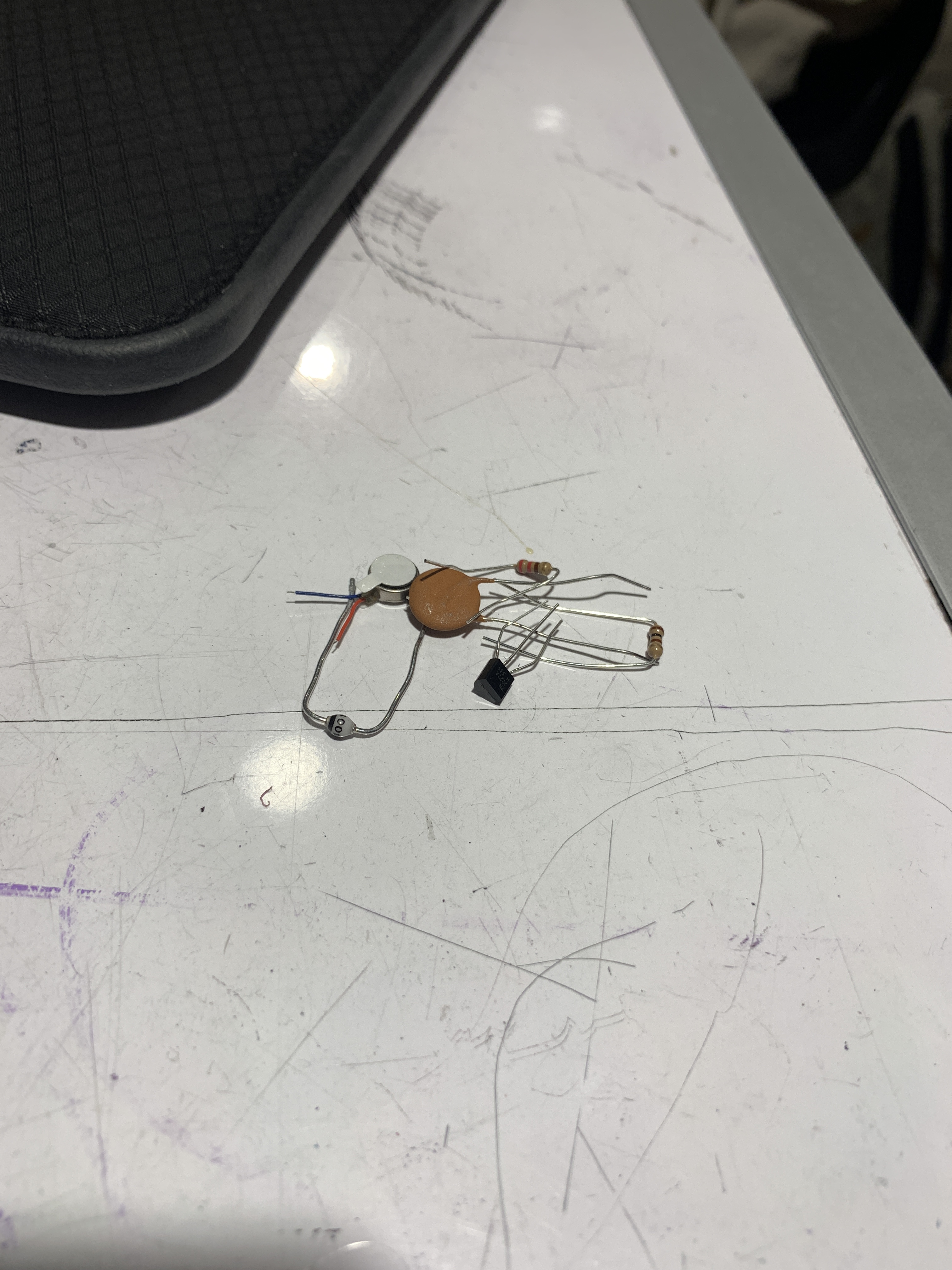
We were originally using all of these parts to wire our vibrating motor, but we learned soon after that we could just use a ULN2803 transistor instead.
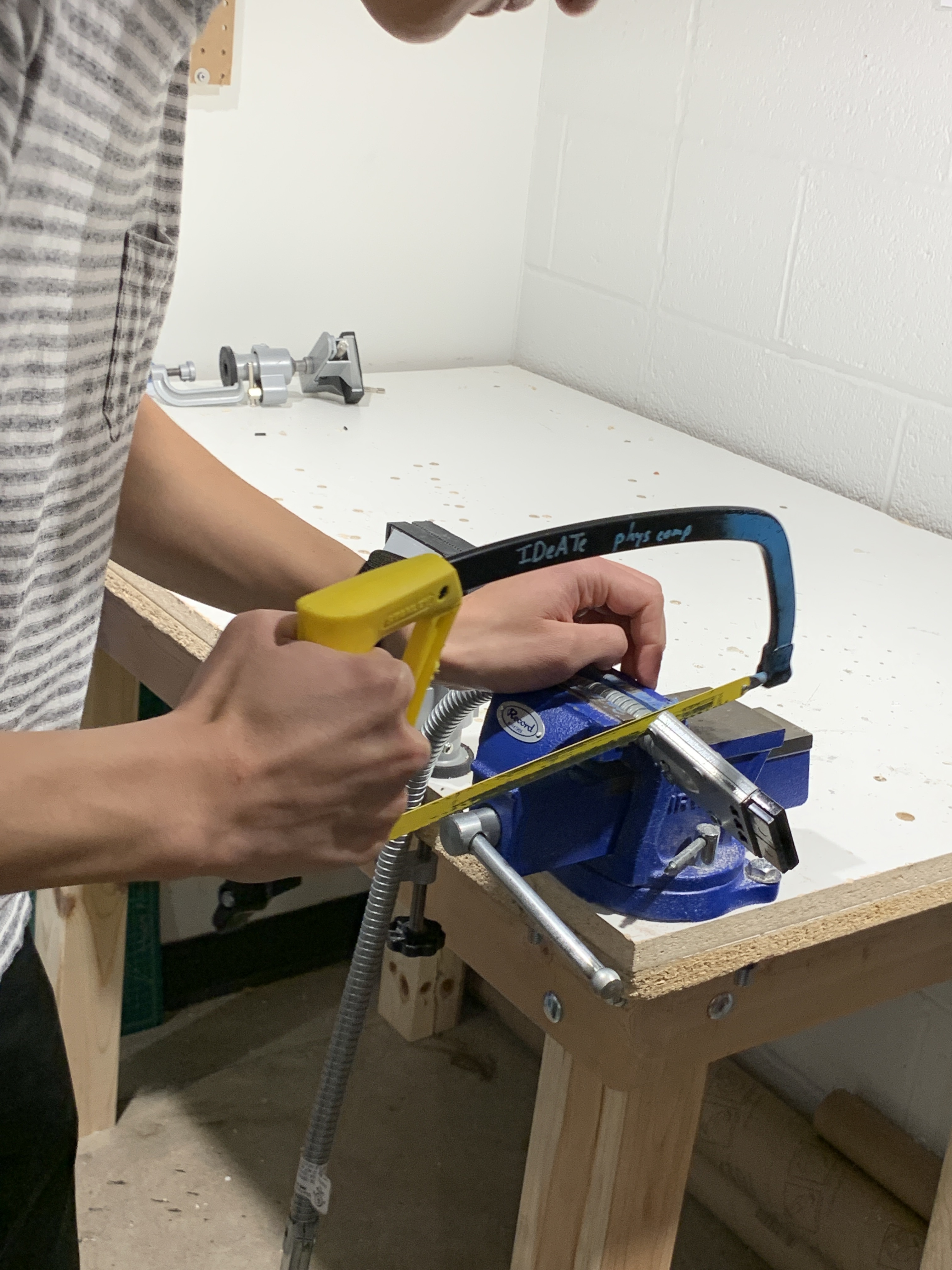
Ian is working with a metal tube that we intended to use over our heart rate monitor because we were running into weird issues with interference from nearby metal objects.
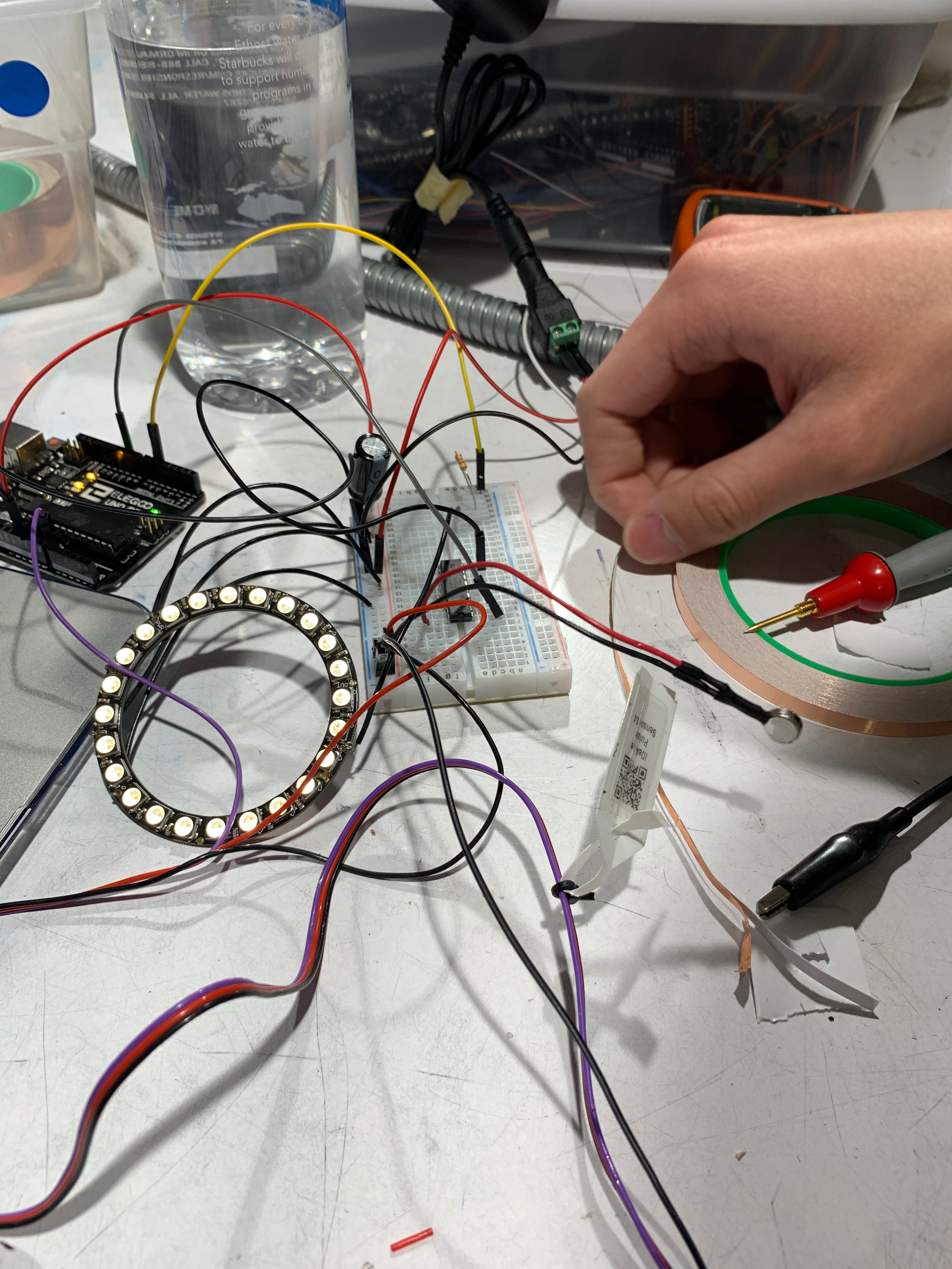
After adding all our basic components (LED ring, heart rate sensor, vibrating motor) it was kind of crazy and we were working to make things as organised as possible, but we were nearing the end of our prototype building.
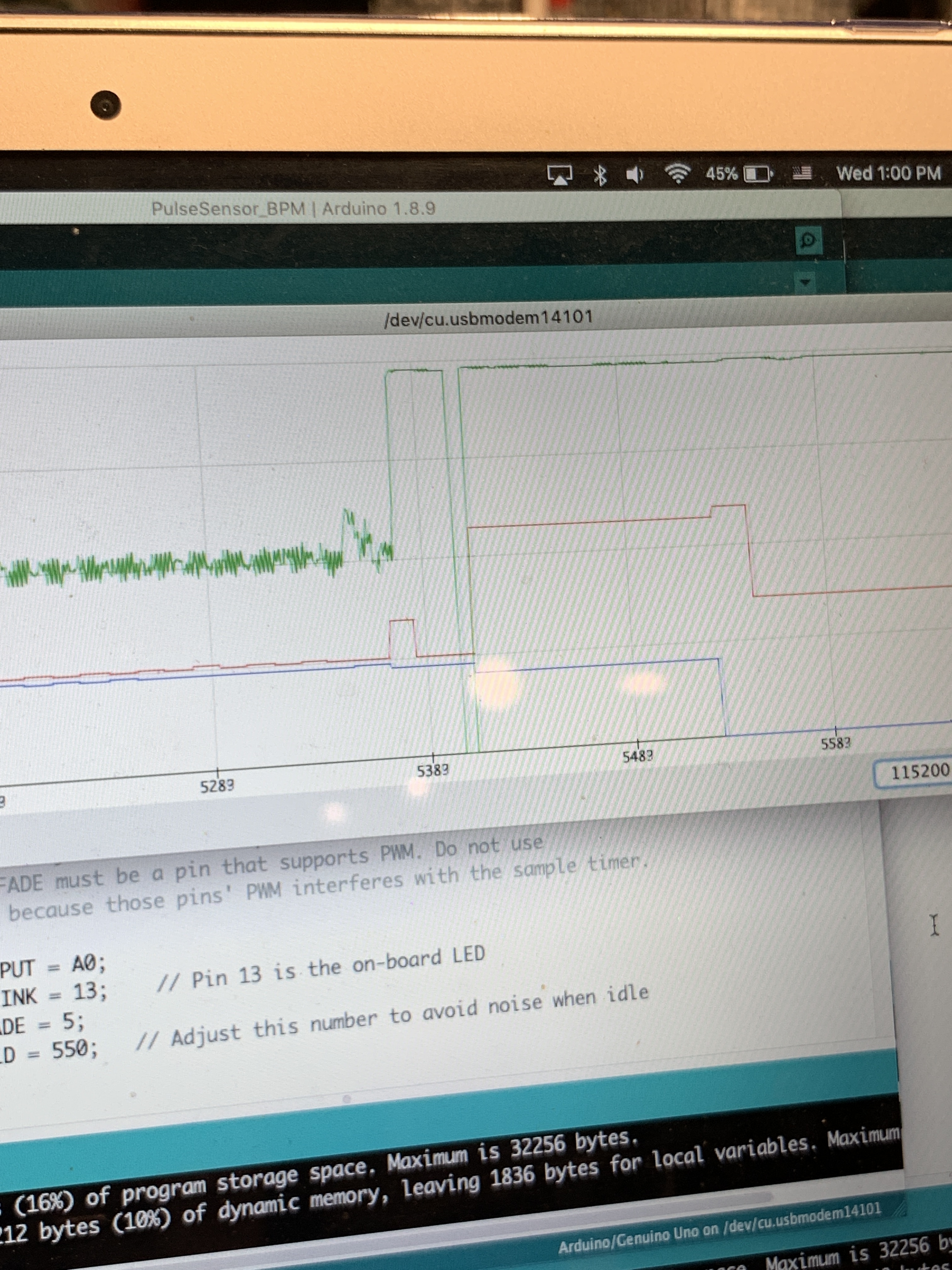
Here (the red line is the heart rate monitor) are some example readings we were getting, where the sudden spikes and dips are due to waving metal objects over the heart rate monitor.
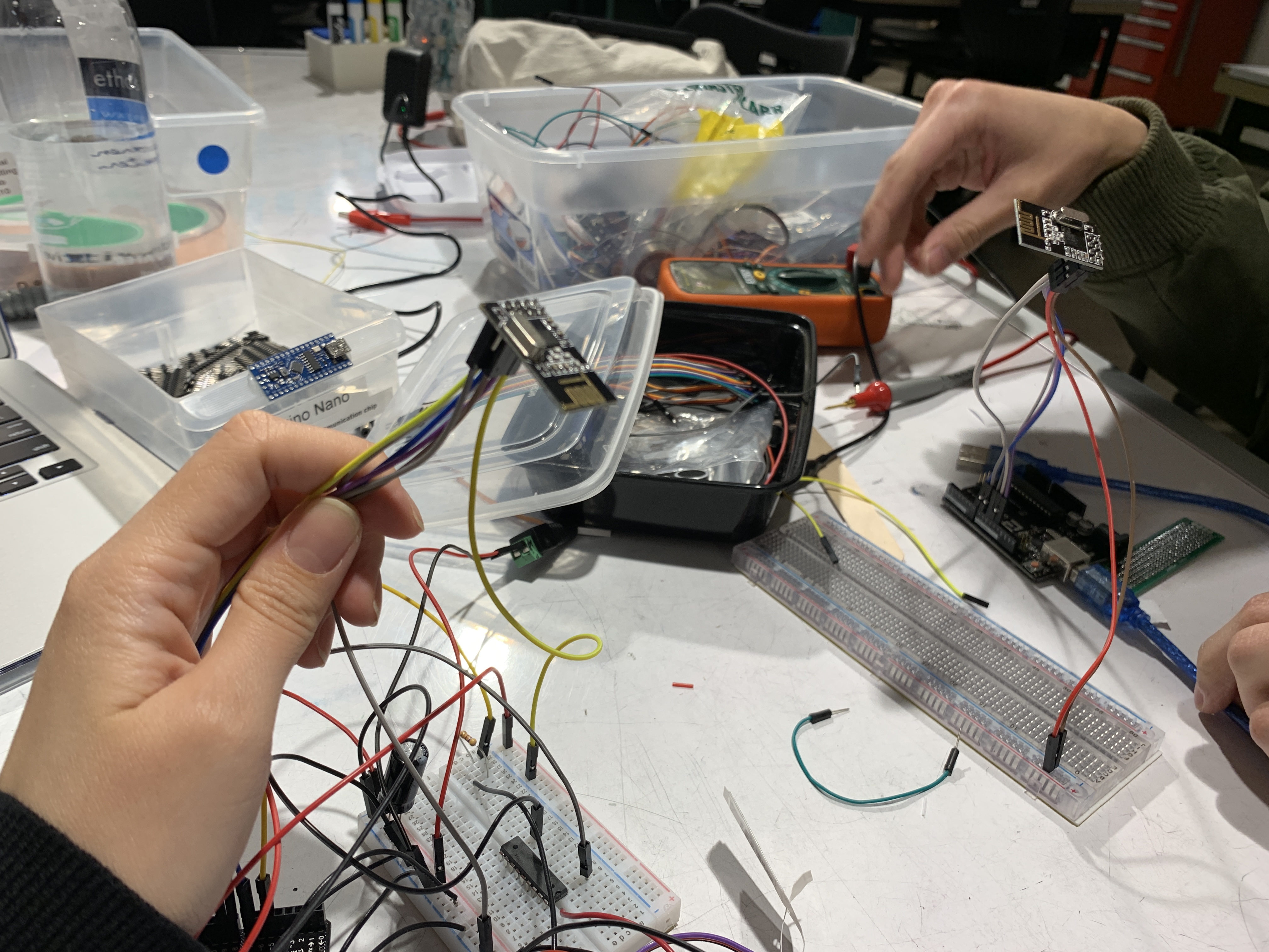
Another feature we worked on was remote data transmission and receiving between 2 Arduinos, so that Elinor can receive data from her portable device on her dock.
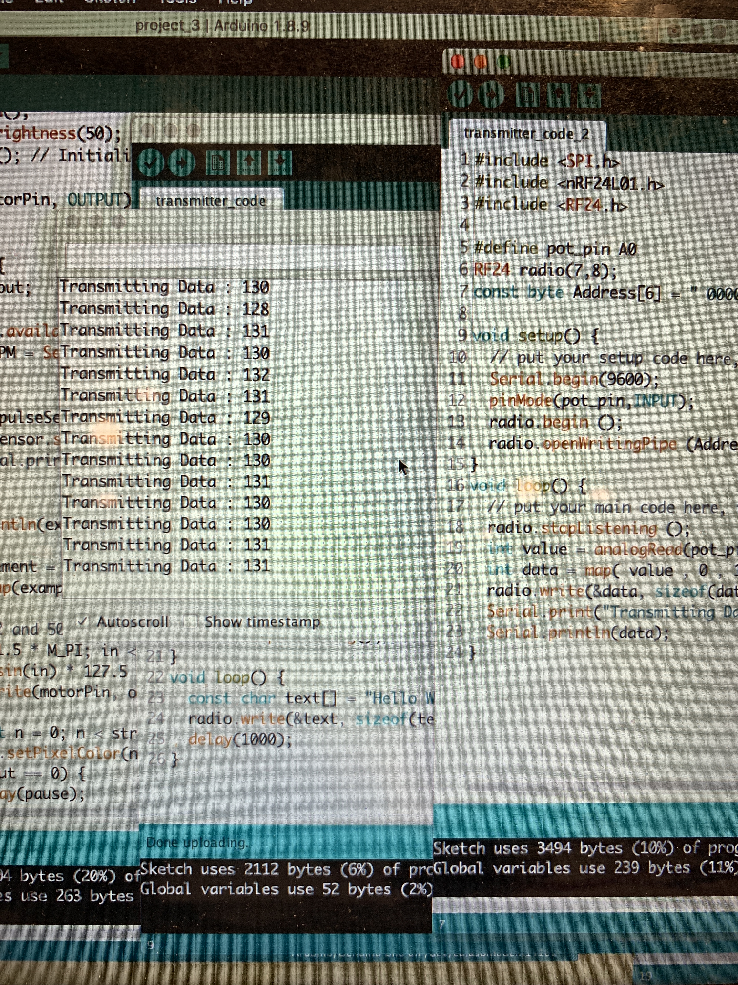
The code for the transmission side of the data transmission/receiving. It took a couple of tries but it ended up working!
Preliminary renders
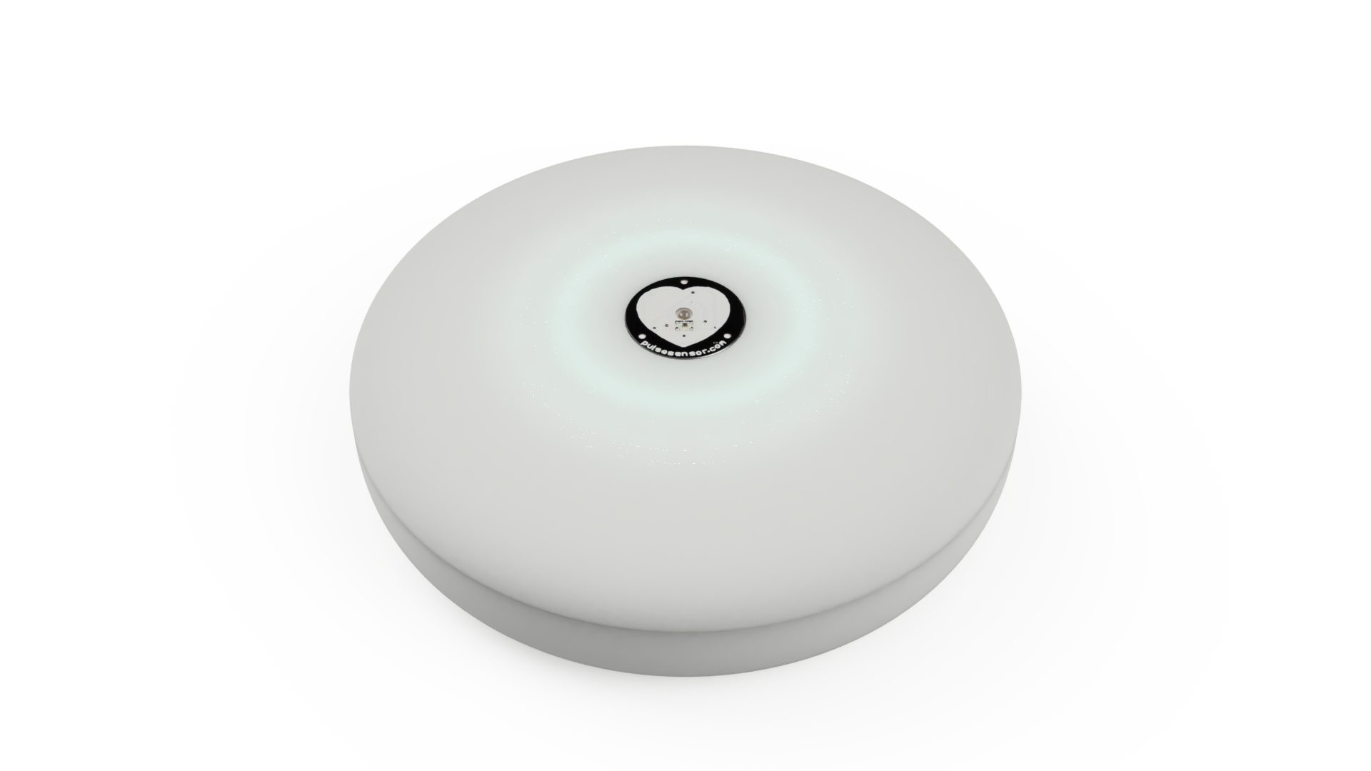
A concept for what the mindfulness device could look like. The LED ring is embedded beneath the surface and diffuses through translucent material.
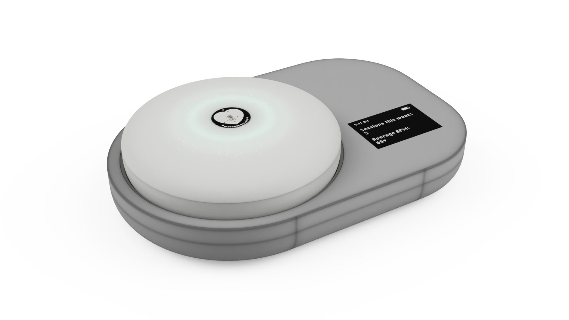
At the end of a day, the “pebble” can be set in its dock to charge and sync data.
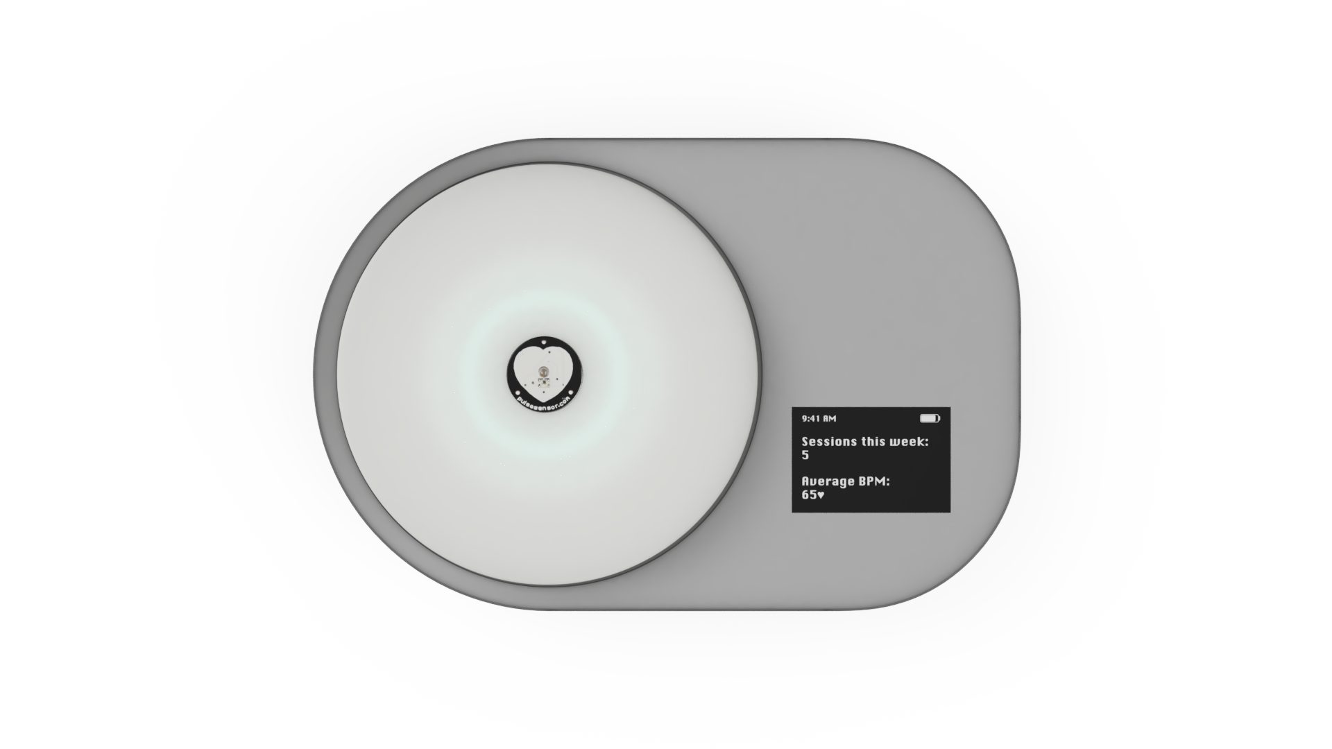
An LCD on the dock provides insights and trends regarding number of sessions a week and heart rate trends.
DISCUSSION
When we first started working on our prototype, we mainly ran into some major issues with the heart rate sensor. On the first couple of days we worked with the part, readings were really stable and showed a lot of promise for our prototype, but some days that we went into the lab to work on it– the sensor would show odd readings that weren’t actually corresponding to our heart rate when we also used other devices like a smartwatch. After testing different theories, we found out that waving metal objects like our phones was causing the readings to spike and dip weirdly. We tried working with a code and adding in some smoothing functions as well as some hardware solutions like covering the part with a metal tube, and ended up wrapping most of the sensor in copper to mitigate the interference of nearby metal objects. For our prototype demo, we inserted code so that BPM can be entered and different speeds of haptic feedback and LED patterns can be visualised.
Some other challenges were related to synchronising the heart rate monitor with both the LED ring and vibrating motor. We wanted both parts to “pulse” in correspondence with the heart rate detected, so that a higher heart rate would map to a faster pulsing and similarly for a slower heart rate. Figuring out the right speed for this pulse took some trial and error and some running up flights of stairs to test for elevated heart rates, but we were able to add in a function that both of us were satisfied with.
The crit on April 8, especially our consultation with Elinor, was really helpful in gauging how Elinor felt about the device at its current state and what she wanted to change about it. She had several ideas for us related to adding in more functionality specifically related to mindfulness, the ergonomic factor of the device shape and sensor placement, and the pulsing component. Elinor was concerned that the device would only act as a heart rate monitor, and suggested adding in some voice control or voice recording playback that plays guided messages of meditative exercises. It was useful to know this information and definitely got us thinking about how we might add in some more functionality without losing the simplicity of the device, since we wanted this to also act as a sort of tactile device that Elinor can physically interact with.
After seeing our renderings, Elinor also mentioned that the placement of the heart rate sensor (on the top surface, right in the middle) could hinder her from being as relaxed as possible, since it isn’t a natural grip for her. The placement of the sensor could possibly be changed from the top to the side of the device so that it reads her heart rate while she holds the pebble in her hand without needing to consciously move her finger to the center.
Next steps
Moving forward, we definitely want to keep Elinor’s considerations at the forefront and work on adding in more functionality that guides her through some relaxation exercises. Due to technical limitations we are unsure if we will be able to implement interactive voice features or voice control, but working on a voice/sound related feature is something to focus on. We are also thinking about creating playlists of calming and meditative music that Elinor can listen to as a supplement to her usage of our device, or a similar solution. After adding some more functionality and finishing up the portable device, we are going to work on the dock and its related features such as charging and data aggregation. The fabrication of the device itself is also really important to us and we want to make sure to have enough time to create a relaxing-looking and feeling device (likely 3D printed).
Additional modes have to also be implemented. Examples would be the lighting/haptic sequence signaling to get ready for a session and different patterns at the end of a session: a sequence to indicate a good session and another to indicate that another session may be in order. Synchronization also has to be hashed out (what the LCD interface looks like, what data is displayed on it, how charging and synchronization works on the backend and human-facing, etc.) Although most major components have been connected to the Arduino with basic functionality, the greatest challenges lie ahead: implementing all necessary features elegantly and effectively and combining electrical components with the physical enclosures.
]]>Our goal is to create a personalized device that will assist an individual in some aspect of their life. In pursuit of this goal, we (Karen and Ian) first needed to learn more about the person we’re designing for, Elinor. Since Elinor was out of town the past week, we had a quick phone call to introduce ourselves and the project briefly before our in-person meeting. We drove out to the suburbs of Wexford, PA, on Friday, March 29th to meet with Elinor at her house, learn more about her life + daily routine, and get to know what type of device might be helpful for her. When we met in person, we focused on seeing her house and environment, as well as learning more details about her lifestyle.
Meeting agenda
Since we met with Elinor first on the phone and then in-person, we planned on learning more basic information about her first, such as:
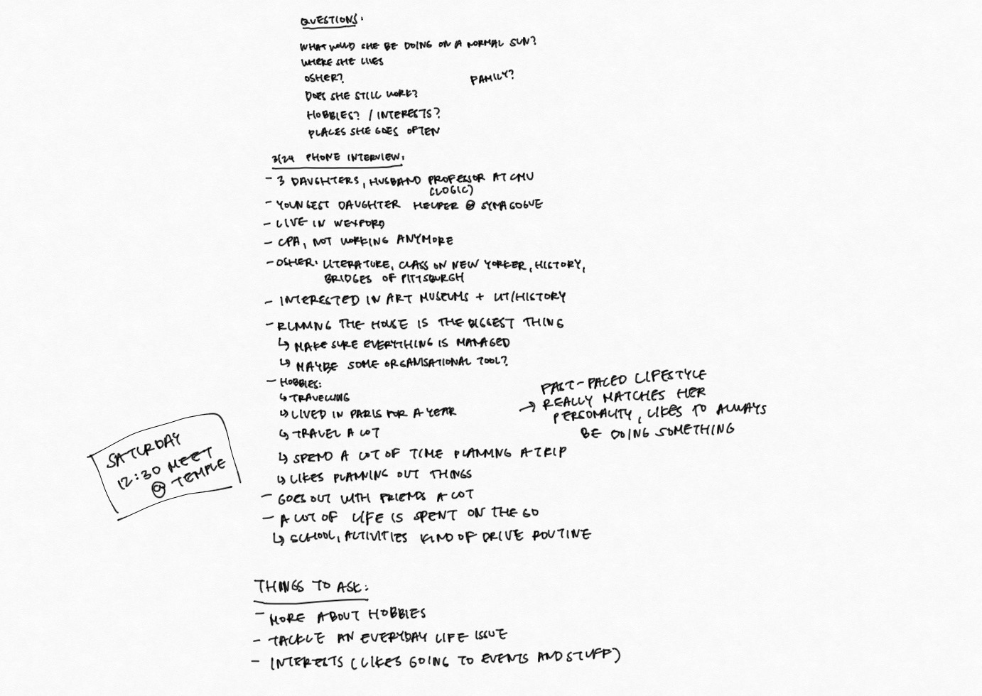
Handwritten notes before interview
After our phone call, we were able to get a sense of her personality and a quick rundown of her daily lifestyle. We were still left with some questions about her hobbies, interests, and what types of issues she might encounter on a daily basis, so we were looking forward to seeing her face-to-face. Before going to her house, we came up with some basic ideas that we wanted to ask her about:
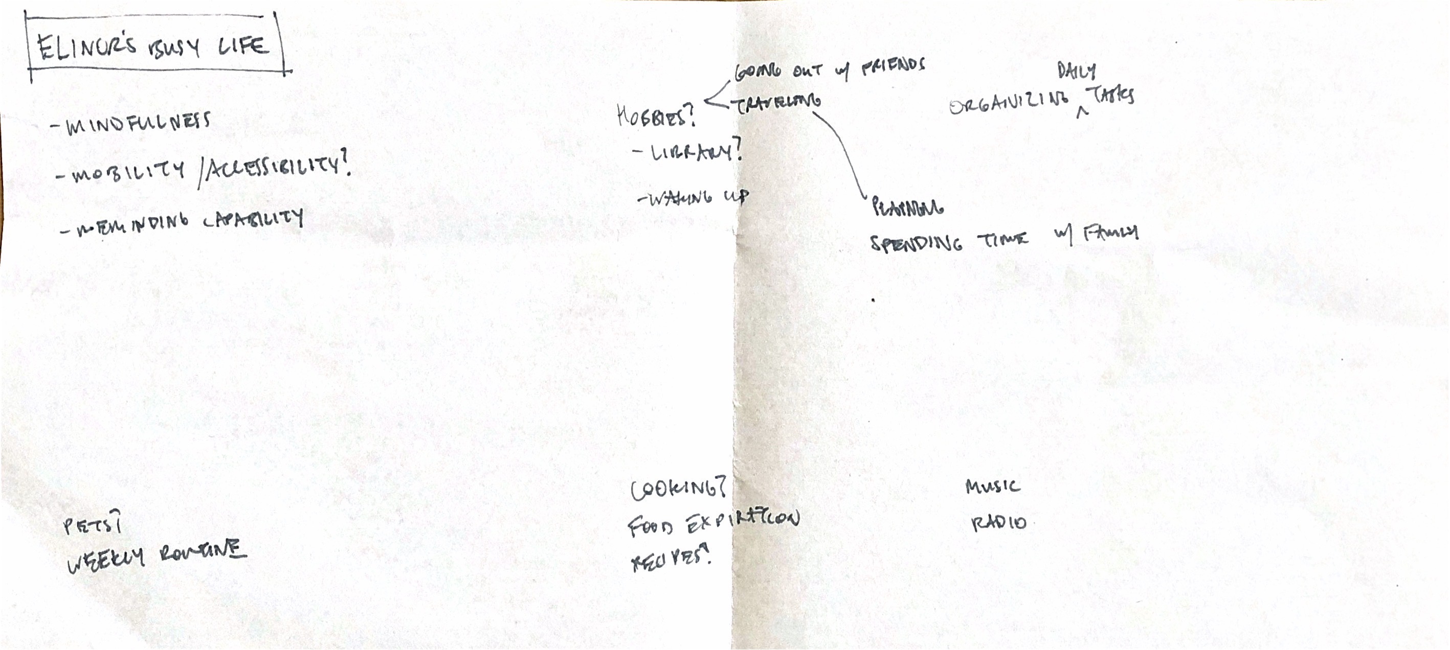
Scanned notes before meeting
For our interview with her, we loosely planned an agenda on our way to her house and wanted to structure our meeting something like this, although we planned on adapting our questions based on any new information we learned or if anything came up that we wanted to address.
- Introduce ourselves and our objective through this project
- Ask about her participation in OSHER classes and some more information about classes she has taken
- A tour of her house and ask her about how she spends her time at home
- Ask her to tell us about her daily routine and hobbies
- Ask about her electronic devices and how she might organise her schedule
- How does she spend her free time
- Ask if she has any issues in her daily life that she might want help with
- Ask her about some ideas that we had after our phone interview, such as mindfulness
- Wrap up, take any photos if needed, say thank you
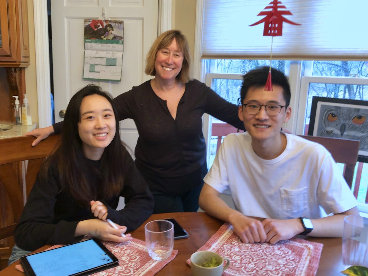
Photo of the three of us, courtesy of Elinor’s daughter Ariella.
Summary + takeaways
Through our conversations with Elinor, we learned that Elinor maintains an active lifestyle and most of her time is spent organizing the lives of her three daughters and other miscellaneous errands that take up her day. Elinor also enjoys travelling, handling investments/stocks, and working with other families in college planning. She described her day-to-day lifestyle as pretty varied and dependent on matching up many different schedules and activities, so we thought that this could potentially be a space for us to explore. Although Elinor really enjoys planning and staying busy, including going to the gym regularly in the mornings, she admitted that she often doesn’t have time to herself to relax and focus on her mindfulness.
Something else that Elinor brought up was that it’s really tedious and time-consuming to organise her mail, since she receives so many different types of mail on a daily basis. Currently, her mail sits in a bag or on her desk before she finds time to go through each one by one. A system that could sort through her mail and keep track of dates when her mail was received seemed like it would be helpful to address this problem.
After going on a tour of her house we learned that her house stays pretty organised and that when Elinor is at home (which isn’t too often), she spends most of the time at her desk on the computer. She also uses an Amazon Echo to play music or do basic commands, and mentioned that integration with her device to serve as a communication device with her daughters would be helpful as well.
Post-meeting
Prior to meeting our client, we were somewhat led to believe that they would require assistance with daily tasks due to their age. However, in our conversations with Elinor, this was clearly not the case. She is about the same age as our parents, raising daughters who are the same age (or younger) than we are. Having recently left her job as a CPA, Elinor has more time to devote to her daughters’ activities, including traveling, managing college applications, and attending extracurricular activities. One could say her energy level exceeded ours, and even conditions that people start to get in their forties (hyperopia or knee issues, esp. when going up and down stairs) she did not have. As a result, our conversation centered around her daily activities. At one point, we were talking about our experiences applying to and attending college. In that sense, it was less of an ‘interview’ with strict question-asker and question-answerer roles and more of a conversation with a friend.
Perhaps if we entered the conversation with that mindset, instead of trying to find an apparent mobility/functional area that could be solved, we could have started ideating on what the device would look like, what it would do, and how it would work, with live feedback from the client. Of course, this can still be accomplished later through email or over the phone/FaceTime, but it would have been nice to have more fleshed out project boundaries earlier in the process.
Overall, we both thought that our meeting was productive and it was really helpful to learn about Elinor in her home environment.
]]>Ian Shei
Winters in Pittsburgh are long and cold, and with the brisk weather comes excessive heating of buildings. Heating through steam radiators invariably drives indoor relative humidity uncomfortably low, causing dry skin, nosebleeds, respiratory problems, and aggravated allergies and skin conditions. It can also dry nasal passages, leading to greater susceptibility in contracting cold viruses. Experts recommend keeping indoor relative humidity between 40 and 60% for comfort, reduction of airborne bacterial and viral transmission, and minimization of mite and fungal populations.
However, most humidifiers, including mine, don’t sense relative humidity and thus rely on manual activation in order to operate. This introduces much guesswork to the process – unless one has a humidity sensor handy, they most likely turn on the humidifier when it “feels” dry (humidity readings in weather forecasts don’t accurately reflect indoor conditions).
This often results in forgetting to turn on the humidifier if one is preoccupied or busy. Personally, the main reason I have a humidifier is because of sensitive skin, but I find that I could be using the humidifier when the cause for irritated skin at the moment is unrelated (stress, sleep deprivation, air pollution, etc.).
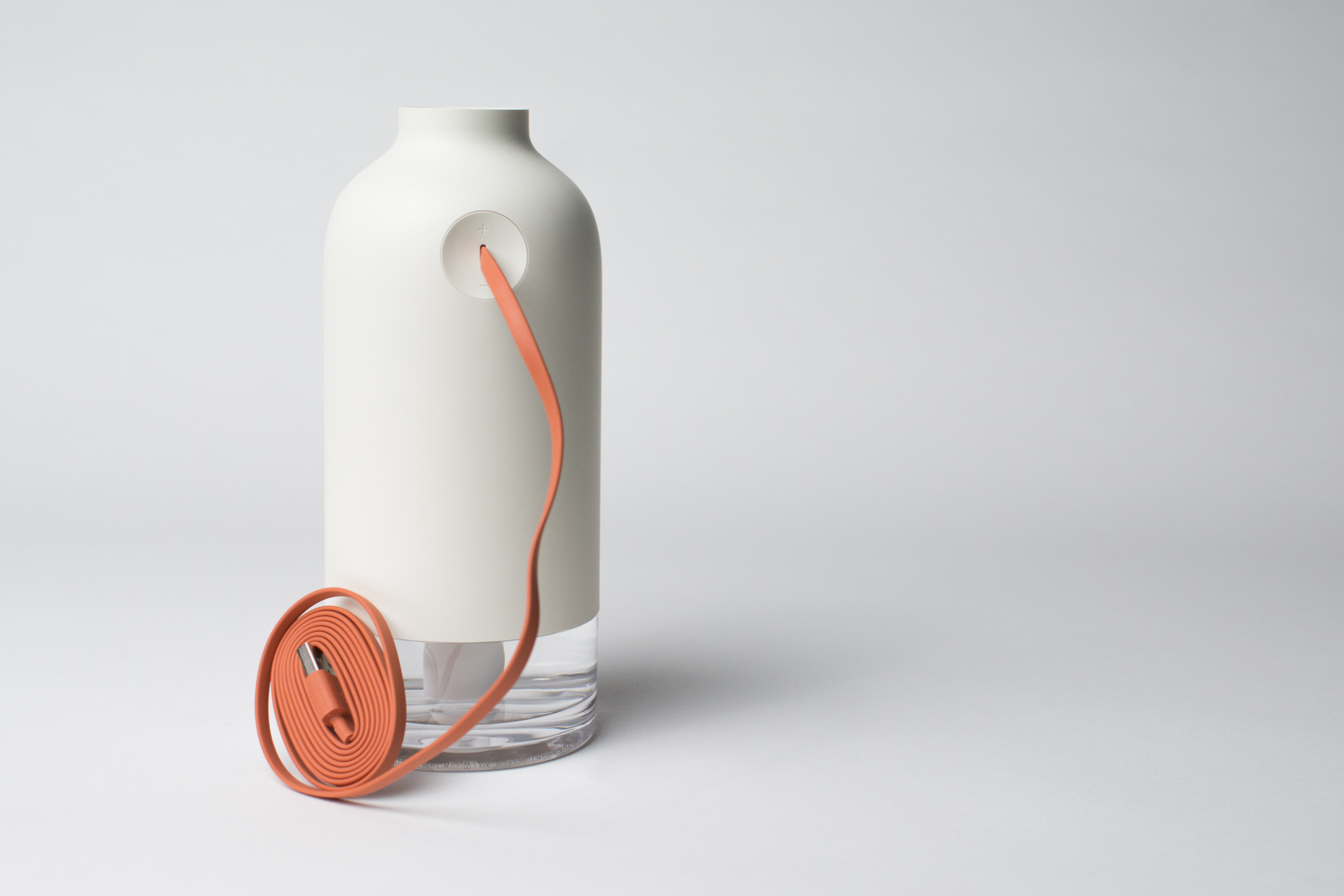
My humidifier. It sits on my desk in my room and is essential to surviving a Pittsburgh winter.
My objective with this project was to create a base for my humidifier that would noticeably signal when the relative humidity in a room had fallen below a set threshold, thus signaling that the humidifier should be turned on. Since monitoring of humidity is constant and automatic, the base could attract a person’s attention using lighting so that they don’t neglect increasing the humidity. By activating based on an environmental measurement, any guesswork in the indoor humidity is eliminated – the humidifier would only be turned on when necessary as dictated by the sensor’s reading.
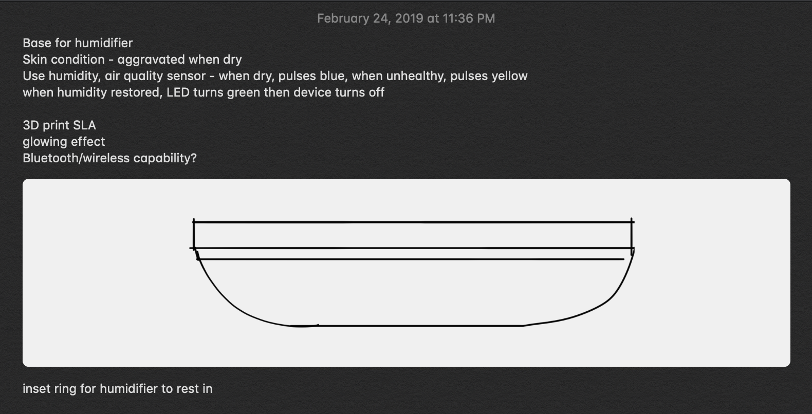
Some notes and a quick phone sketch early in the process.
I began by wiring and testing this project’s essential component: an inexpensive DHT22 temperature and humidity sensor. To verify that the part functioned as described, I used an Arduino Uno to act as an intermediate between the DHT22 and the serial monitor on my computer.
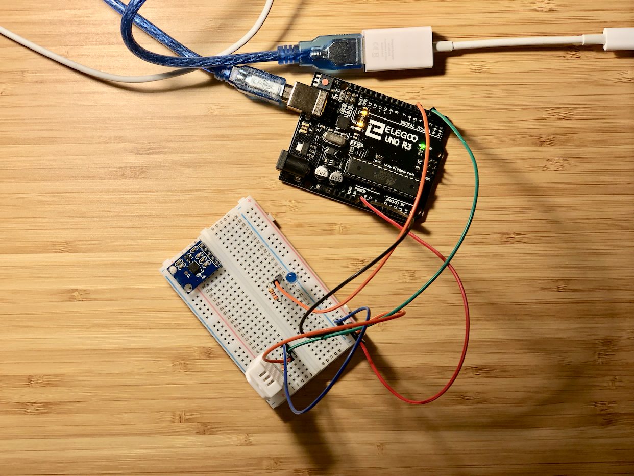
The DHT22 sensor (the white block in the lower left corner of the breadboard) connected to an Uno.
With the humidity sensor verified to be working, I connected a rotary encoder, ambient light sensor, and a ring of 24 RGBW LEDs called a NeoPixel Ring. The NeoPixel’s purpose is to display the relative humidity through pulsing (the faster the pulsing, the drier the air) in order to alert the owner to turn on a humidifier. It also works with the rotary encoder to adjust the humidity level below which the LEDs will turn on, serving as a display to set the threshold. Finally, the ambient light sensor controls the brightness of the LEDs so as to not be blinding in a dark room.
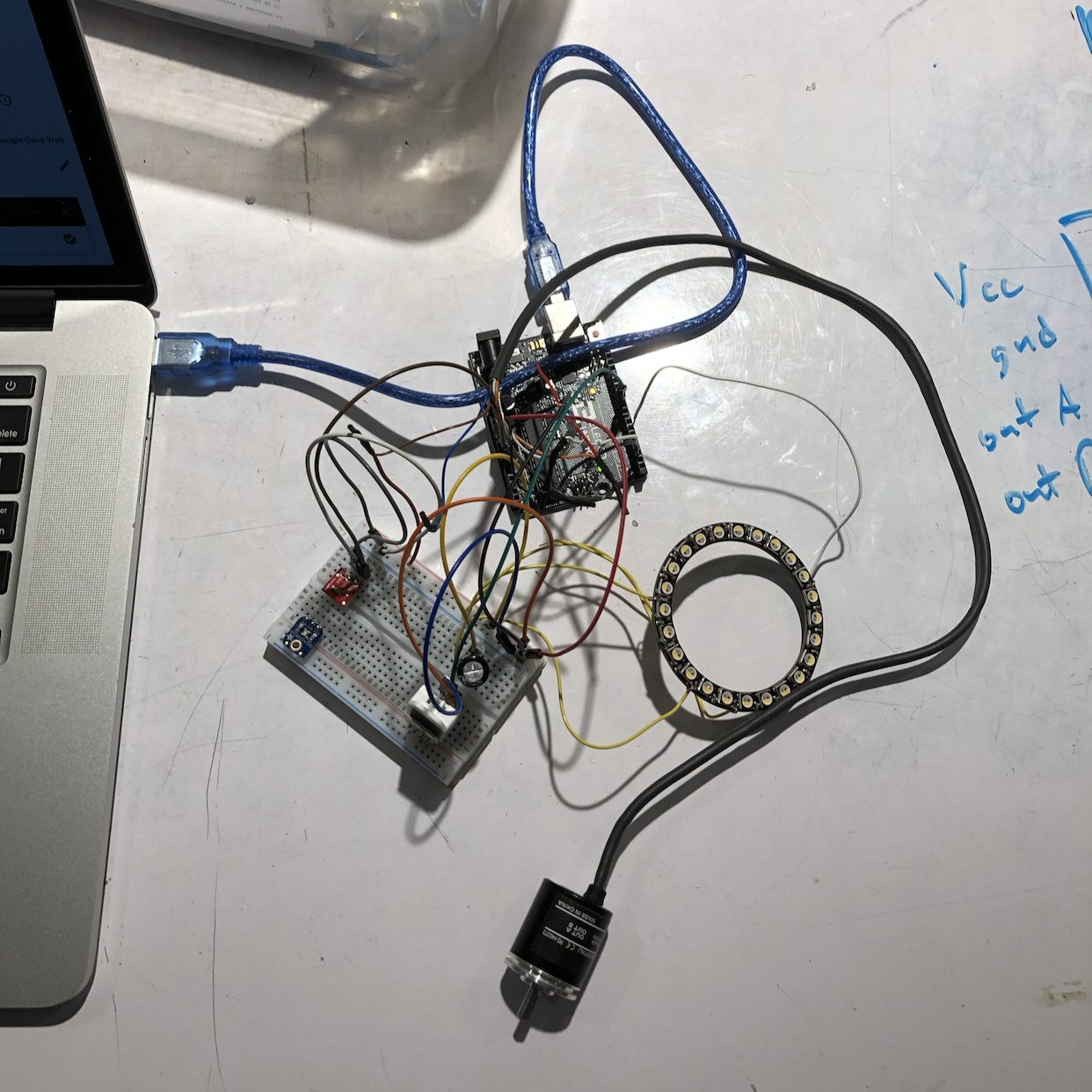
The basic components (DHT and ambient light sensors, NeoPixel Ring, rotary encoder) connected to an Arduino. The rotary encoder pictured was used for testing and verification and was replaced with a smaller one later.
Because everything had to fit inside an enclosure approximately 5″ x 5″ x 1.25″, minimizing the footprint of every component and connection was key. I tried to use an ATTiny85 to handle and control all the components but was unable to get it to drive the NeoPixel in a reasonable amount of time, so I settled on using an Arduino Nano instead. While the rotary encoder pictured above had great resolution and was very robust (it’s commonly used in robotics applications), its z-height was too big to fit in the casing so I chose a smaller component instead.
Working out the programming with all components proved to be a challenge, even without the fuss of the ATTiny85. Appropriately sequencing and implementing logic was essential in managing all the possible modes of the system, while controlling the NeoPixel was essential in making visual feedback polished and natural. The pulsing of the LEDs is accomplished with a sine function, a smoothing algorithm ensures that sudden changes in ambient light don’t noticeably affect LED output, and millis() is used in favor of delays to make the system as responsive as possible. My thanks to Eric Mendez and Robert Zacharias, who were extremely helpful in troubleshooting and explaining the logic of implementing multiple aspects.
Once I had ensured that the electronics were working as designed, I optimized the LED brightness output vis-à-vis the ambient light sensor and added a simple piezoelectric buzzer to provide auditory feedback when setting the threshold humidity, corresponding with the NeoPixel. It’s better visualized in the video below:
A quick rundown of the status LEDs:
- Blue pulsing ring – Relative humidity is below threshold humidity. The drier the air, the faster the pulsing.
- Green ring – Relative humidity is at or above threshold humidity. Appears for a few seconds, then fades.
- Individual LEDs turning on/off sequentially – Currently in edit mode; turn dial to adjust threshold humidity.
At the same time, I worked on designing an enclosure that would house all the components and also support the humidifier. Sketches of different profiles and arrangements of components gradually yielded a CAD model, seen below.
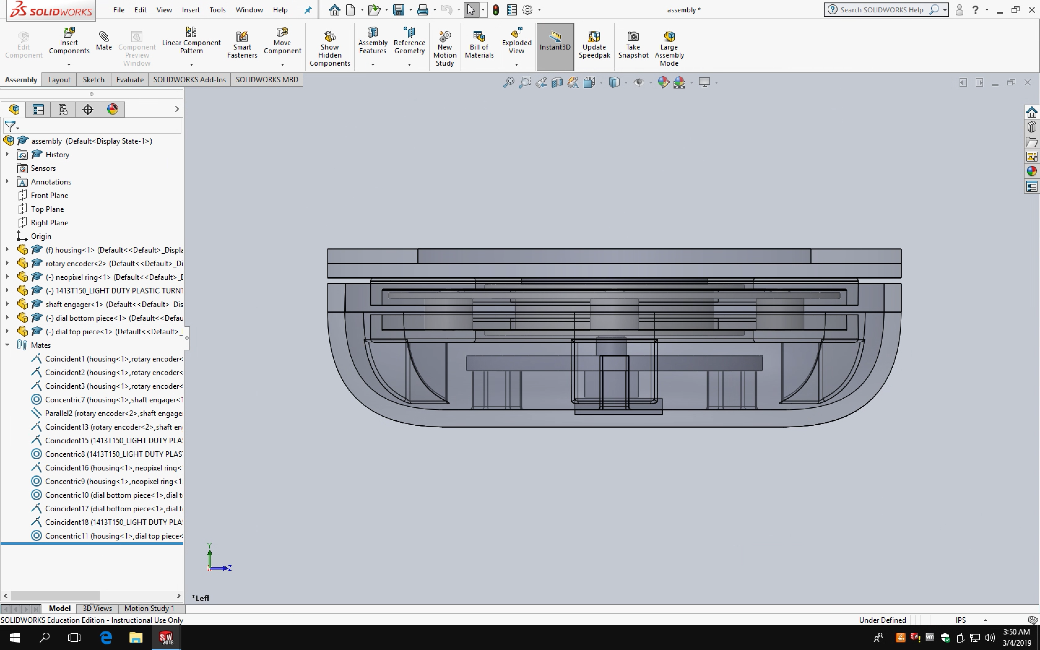
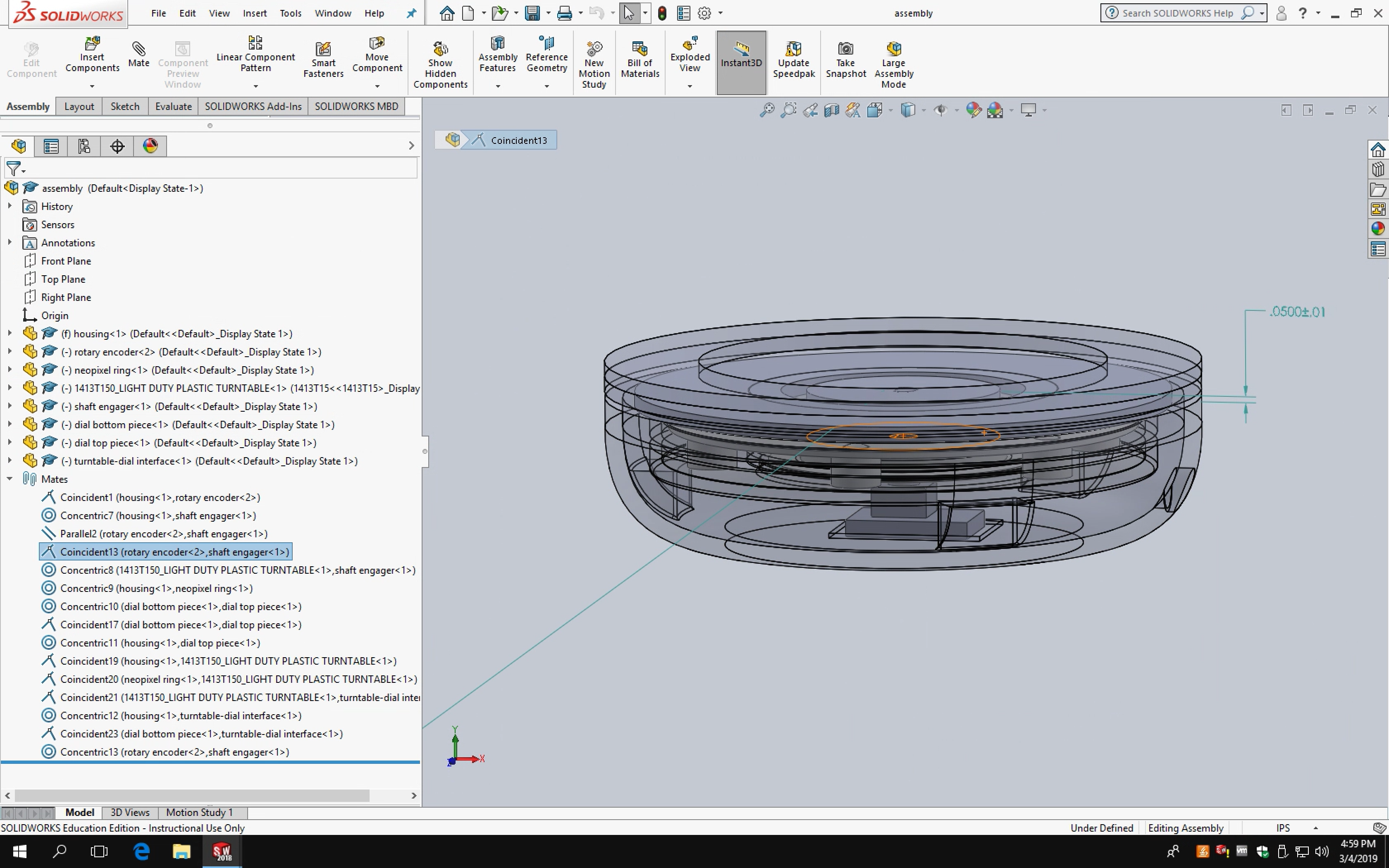
Space is a premium in the first “final” enclosure design.
I counted on a turntable from McMaster-Carr to be transparent like on the website (it was white). Since this arrangement had the NeoPixel directly under the turntable, I had to redesign almost all the internal components to use a different bearing. A positive side effect was that being forced to use a different bearing meant that I could use a smaller component, freeing up valuable space inside the enclosure.
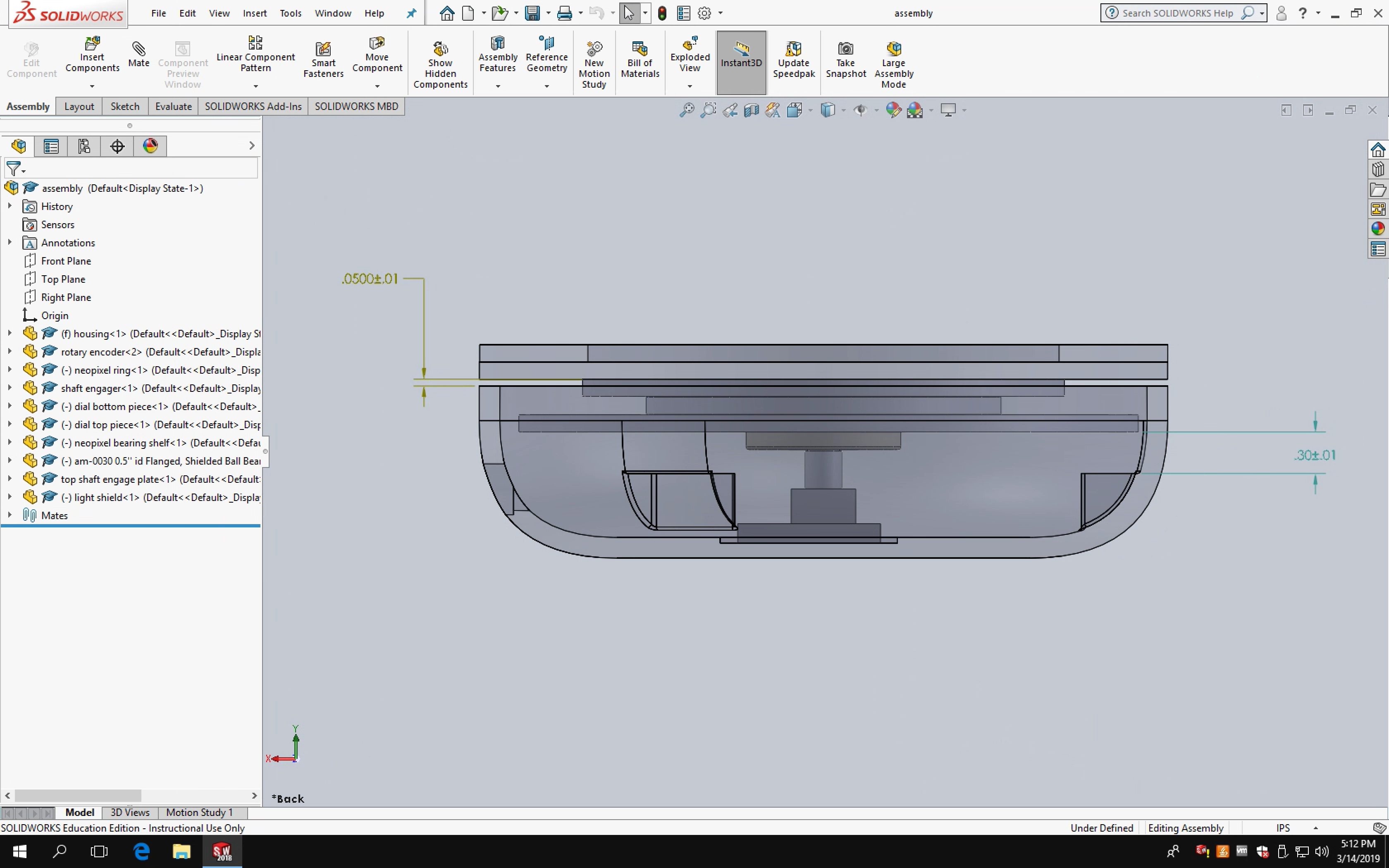
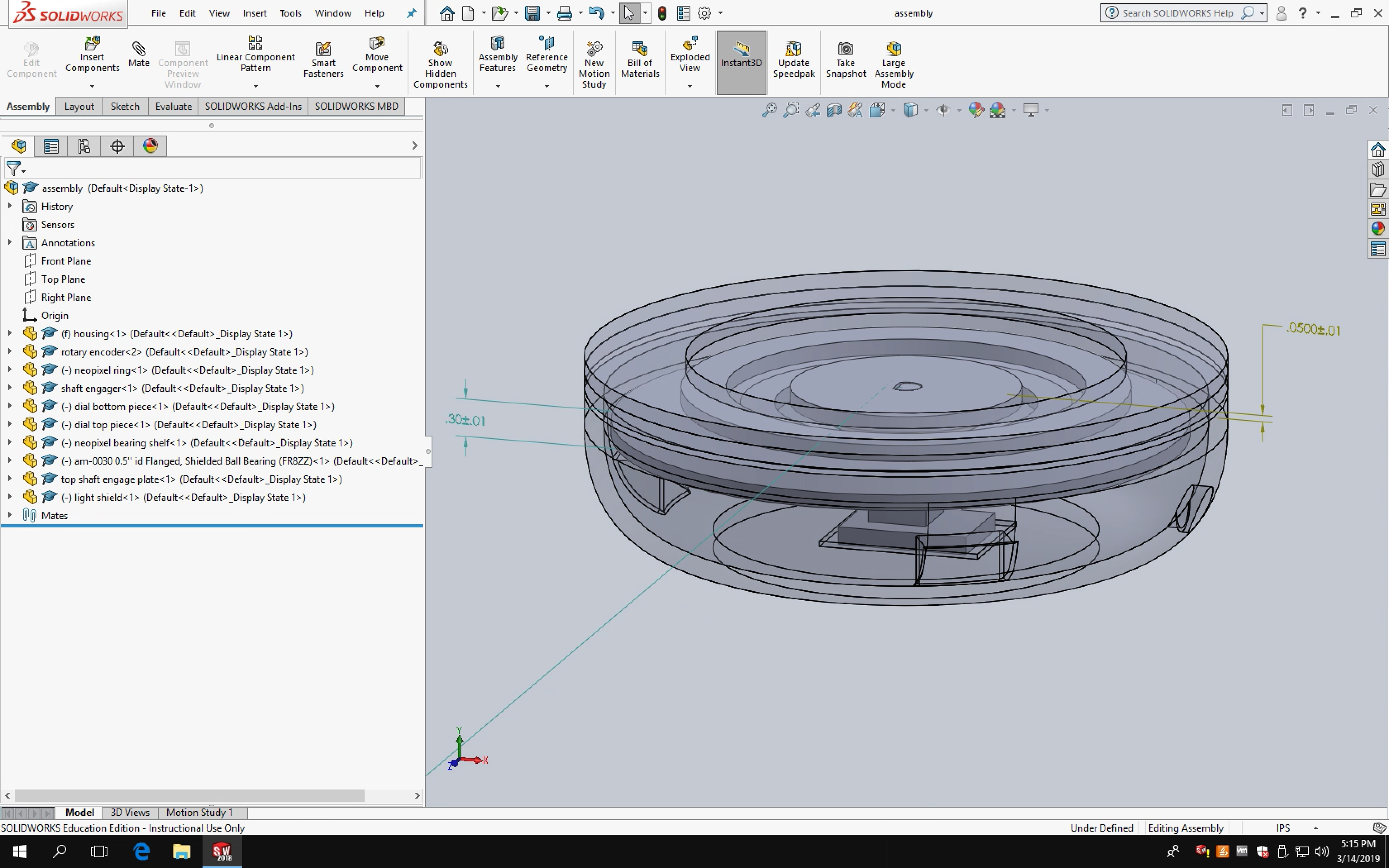
With the enclosure design pretty much set, I 3D-printed and laser cut components. I originally wanted to use an SLA printer, but given that this was the first print (Form 2 prints are expensive) and the specific resin I wanted wasn’t available, I used a traditional FDM printer instead. With a little modification, the housing can also be made of wood and turned on a lathe.
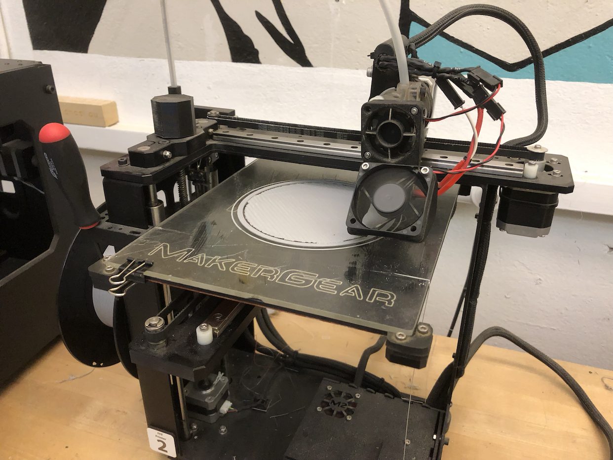
During printing.
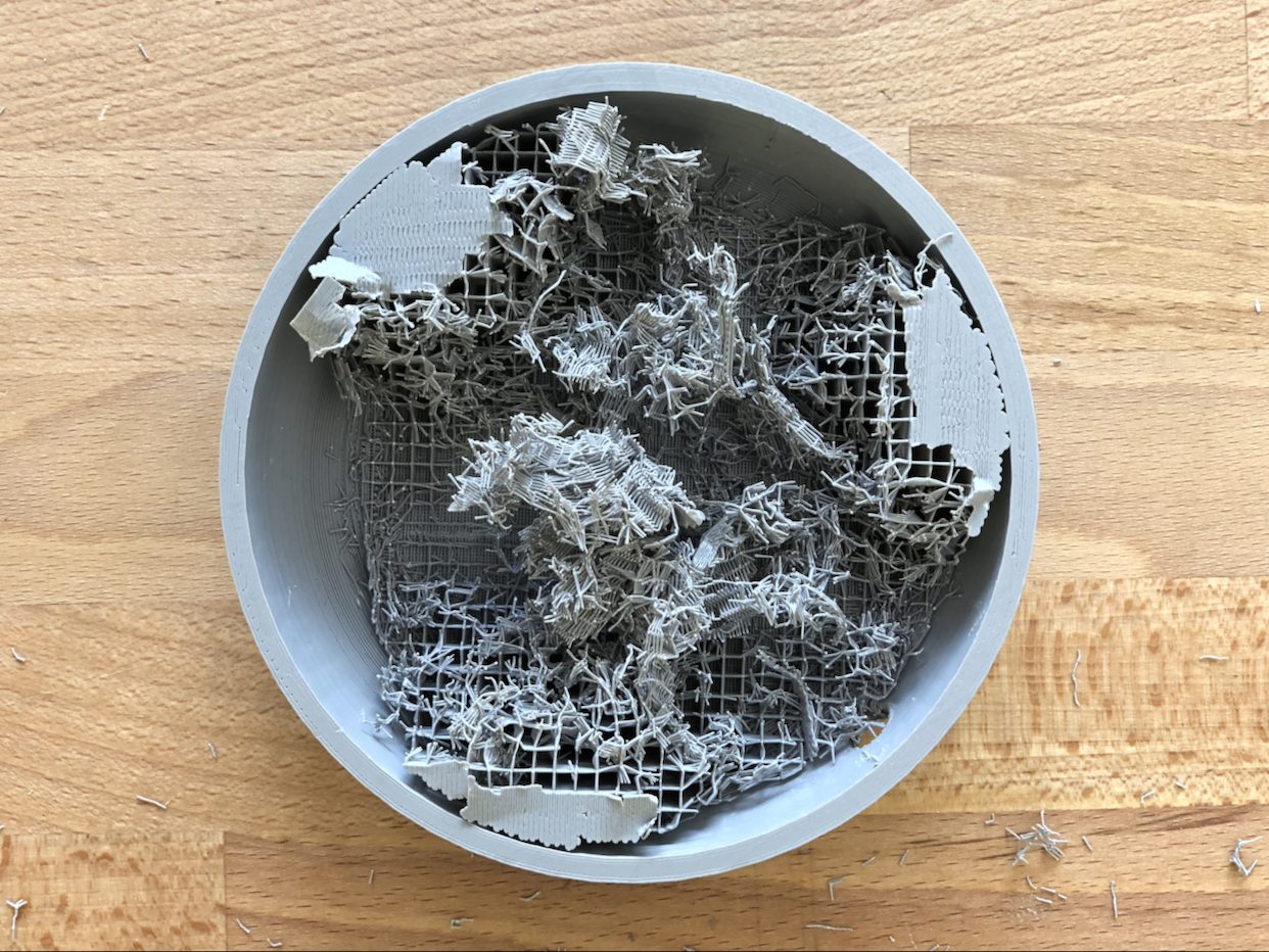
Post-print. Breaking off all the supports took some time.
Other parts of the enclosure, including the top dial, were made from laser cut acrylic derived from the same CAD file. Since the enclosure has a circular profile with a rotary encoder at the center, carefully aligning differently-sized components to be concentric was essential.
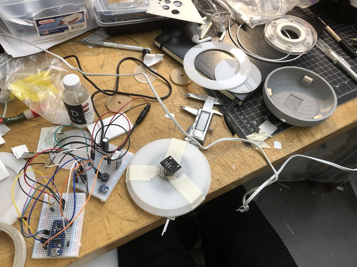
Bringing together the sub-assemblies of the enclosure.
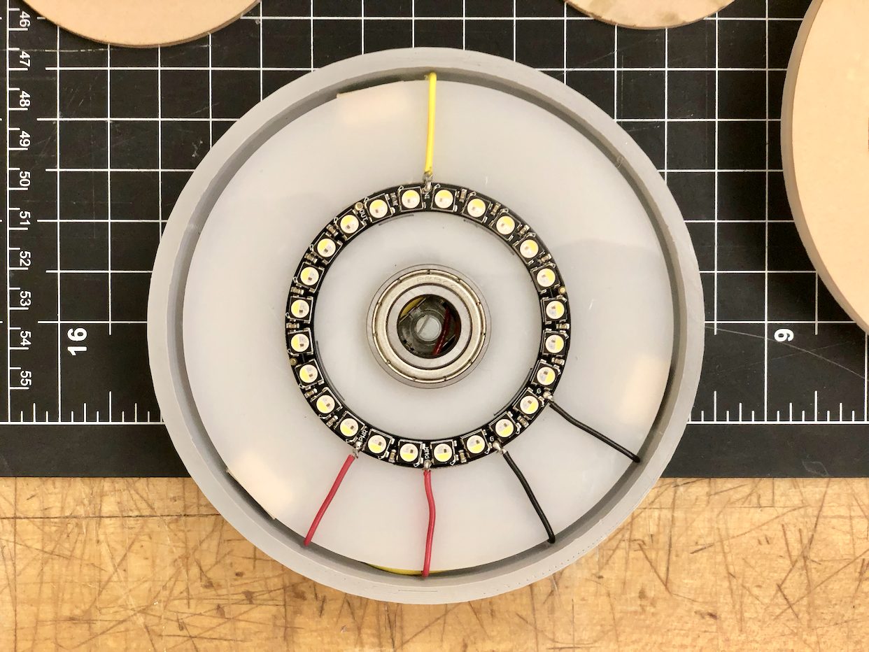
Testing fit of the the NeoPixel-wiring-bearing subassembly within the enclosure.
With the enclosure parts made, it was time to transfer the electronics inside. I soldered them to a flexible PCB, thinking that the flexibility and easy resizability of the board would help fit all the parts inside the housing. However, testing upon solder completion revealed that the connections were already compromised. The PCB is able to flex, but I hadn’t considered that flexing solder points would eventually cause them to crack and separate from the board. In the end, the electronics would only function intermittently if held at extreme angles.
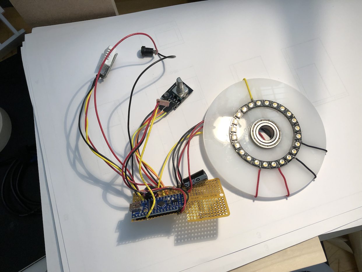
Soldering right components with rigid solder to a flexible PCB was not a good idea.
I had to rewire everything, including a new Arduino Nano to a new rigid PCB which I cut down to size. Luckily, everything still fit inside the housing.
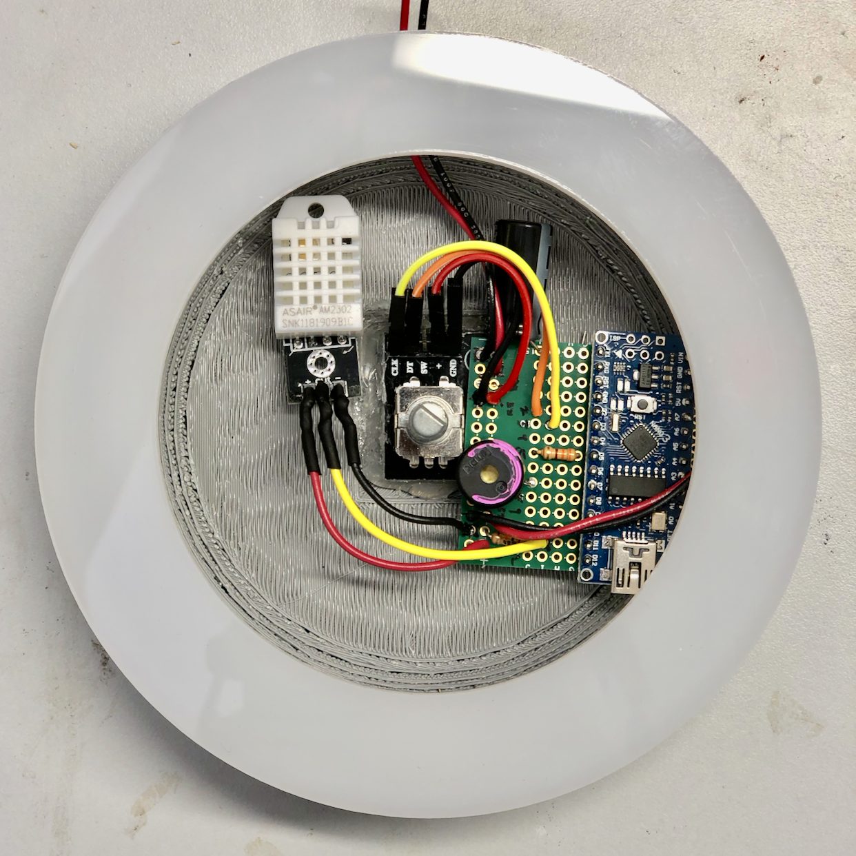
In the process of rewiring components to a new (rigid) PCB.
In all previous steps, the Nano accepted code upload fine and functioned as designed. Other people in the class had run into issues with uploading to the Nano and electrical faults, but I had yet to experience these issues until everything (including the new Nano) was soldered together. I had tested this Nano with the Blink sketch and my code prior to transferring everything from a breadboard to the PCB and it performed as expected, but once I had finished soldering and needed to reupload my code, it failed.
Fortunately, I was able to upload the code with a Windows PC. Afterwards, I assembled the base.
Photos
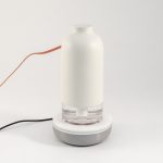
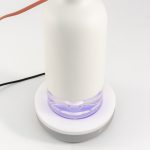
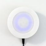
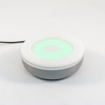
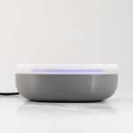
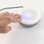
A pulsing blue pattern indicates that it’s currently drier than the set threshold.
To adjust the threshold humidity, spin the top dial. If the relative humidity is at or above the threshold, a green pattern is visible.
Discussion
Response
“Could there be a component that controls the ticking sound (ie on/off)?”
I can see how a clicking sound would be undesirable in certain situations, but the piezoelectric buzzer used is so quiet (especially when contained in the enclosure) that it probably won’t be an issue. It’s quieter than the Home button sound effect in iPhone 7 and 8.
“So one question I have is it’s a good idea for this to be something that you have to remove the humidifier to see/interact with? Would it be better if you could see the lights when the humidifier is docked?”
In theory one would not frequently adjust the threshold humidity once it’s set and the humidifier is quite small and light (about the size of a water bottle) that it’s easy to take off, adjust the threshold on the base, and put back on top. The base of the humidifier is clear plastic so the LEDs are visible when on.
Self critique
I’m quite relieved that this project eventually worked after several significant hardware failures and challenges. I wanted to make the humidifier base to the best of my ability so that I could include it in my portfolio, so I spent considerable time on programming, design, and fabrication. As an early iteration, the physical design of the base could use many refinements – I already have some sketches and CAD files of forms I think would work better – but I’m glad I eventually reached the goal of having a physical base that functions as envisioned.
What I learned
In the future I will definitely avoid flexible PCBs in my projects.
Balancing objectives for the code took quite some time. For example, I wanted to use a smoothing function tying the ambient light sensor (ALS) readings to the LED outputs, but the particular array implementation I was trying requires multiple readings in order to establish an average that reflects current conditions. Normally, this wouldn’t be an issue since the ALS readings happen very quickly, but because of the sin function used to control LED pulsing, ALS readings were delayed and thus the LEDs would only very slowly increase brightness when the device was first plugged in.
When depending on many different manufactured parts from many different vendors, sometimes a part does not function or look as described. I had a few of these obstacles pop up over the course of this project and had to redesign around those constraints. While not ideal, these issues pop up quite frequently during the manufacturing and assembly of actual products (unless every component is designed and manufactured in-house). As an industrial design student, handling these issues provided a valuable learning experience. I can attest that “hardware is hard.”
Next steps
The most immediate next step is to refine the design of the enclosure to be more cohesive. I’ve already started sketching and modeling more developed forms, continuing to think about materials and finishes that would serve the product well.
Now that I know how all the electronic components inside are wired and function, I could also, in the future, design a custom PCB that would be mounted in the housing and connect all the components together. This would do away with messy and unreliable wires jumping from a small rectangular board to components situated all around and serve to make the product more robust and refined internally.
Finally, while the NeoPixel Ring functioned very well, it is sold in only a few sizes. Thus, while the outer diameter of the base measures 5″, the LED ring is quite a bit smaller. I would have liked for the LEDs to be closer to the outer edge of the enclosure. With a custom assembly of LEDs this would theoretically possible, but I’ve already had so much trouble wiring existing components that creating an entirely new and complex electronic part would be something very far down the road.
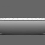
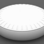
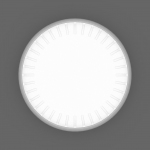
Renders of a new design.
Schematic
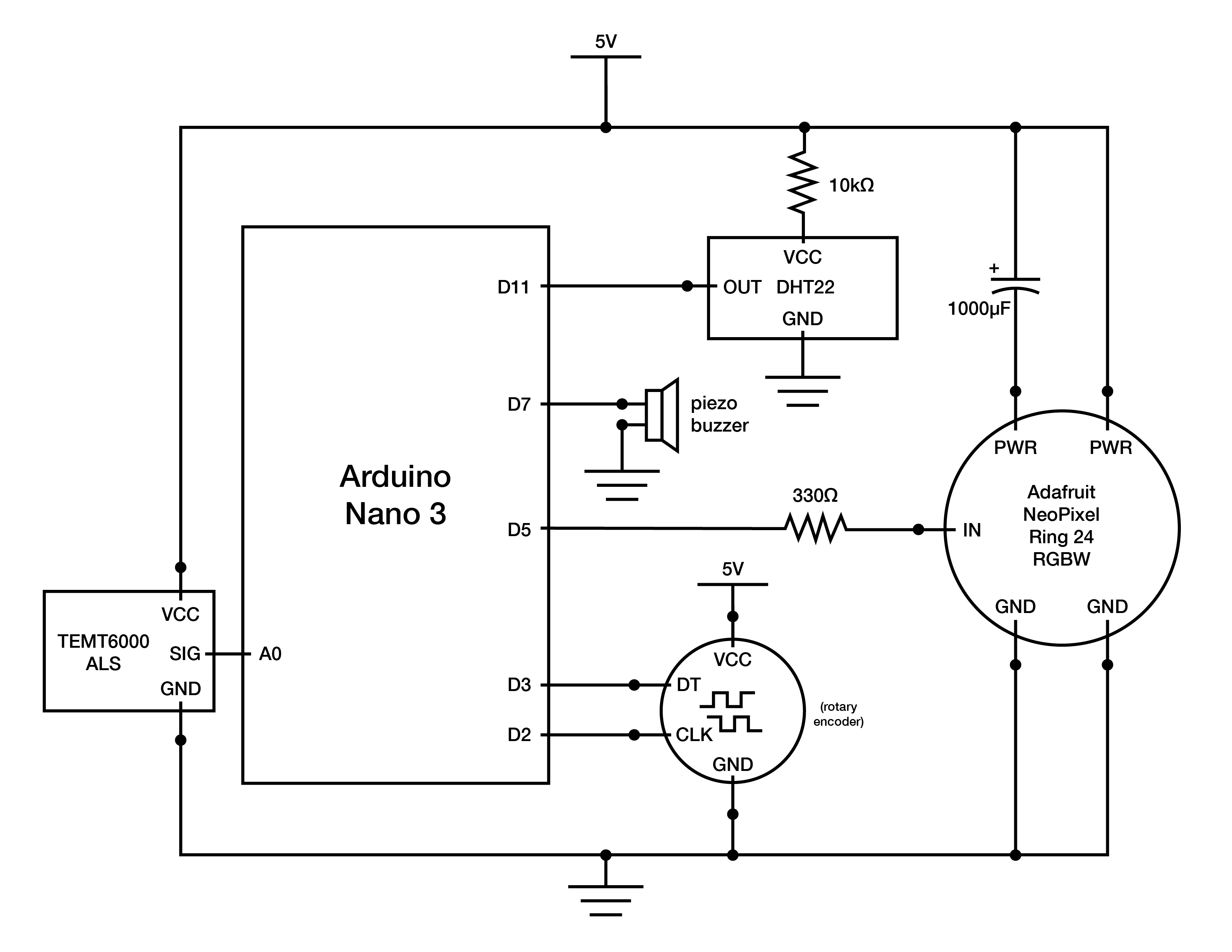
Code
/* Humidifier Base
 *
 * Ian Shei
 *
 * Description: Implements functionality for a custom-designed humidifier base
 * that reads the relative humidity in a room. If the humidity is lower than the
 * set threshold, LEDs mounted near the top of the base will pulse to notify the
 * user to turn on the humidifier – the faster the pulsing, the drier then air.
 * One can set the threshold humidity by turning the dial forming the top of the
 * base, with visual and auditory feedback from the LEDs and a speaker,
 * respectively. Once the relative humidity meets the threshold, the LEDs will
 * turn green for a few seconds then turn off, indicating that the humidifier no
 * longer needs to be on.
 *
 * Adafruit NeoPixel implementation adapted from Adafruit_Neopixel library.
 * Available via https://learn.adafruit.com/adafruit-neopixel-uberguide/arduino-library-installation.
 *
 * DHT sensor implementation adapted from Adafruit DHT sensor library. Available
 * via https://learn.adafruit.com/dht/using-a-dhtxx-sensor.
 *
 * mapfloat function adapted from user "skumlerud" on forum.arduino.cc. Available
 * via http://forum.arduino.cc/index.php?topic=3922.0.
 *
 * Smoothing implementation adapted from David A. Mellis & Tom Igoe's example at
 * http://www.arduino.cc/en/Tutorial/Smoothing.
 *
 * millis() rollover implementation adapted from James Lewis' example at
 * https://www.baldengineer.com/arduino-how-do-you-reset-millis.html.
 *
 * Piezoelectric tick implementation adapted from user "el_supremo" on
 * forum.arduino.cc. Available at https://forum.arduino.cc/index.php?topic=299032.0.
 *
 * LED pulsing implementation adapted from MikeGrusin's Sparkfun tutorial.
 * Available at https://www.sparkfun.com/tutorials/329.
 *
 * Encoder implementation adapted from Paul Stoffregen's Quadrature Encoder Library
 * for Arduino. Available at https://github.com/PaulStoffregen/Encoder.
*/

#include "DHT.h"
#include "math.h"

#include <Adafruit_NeoPixel.h>
#ifdef __AVR__
  #include <avr/power.h>
#endif

// setting up encoder
#include <Encoder.h>
long previous; // previous position reading of encoder
long current; // current position reading of encoder
int ledIndex = 11; // 24 LEDs in NeoPixel Ring. By default, the threshold humidity is set at 50% (hence index of 11).
int thresholdLed = 0; // thresholdLed takes value of ledIndex when ledIndex is changed
Encoder myEnc(2, 3);

// setting up NeoPixel, DHT sensor, ambient light sensor, speaker pins
#define STRIPPIN 5 // NeoPixel Ring
#define DHTPIN 11
#define DHTTYPE DHT22
#define LIGHTSENSORPIN A0
#define TICK_PIN 7

Adafruit_NeoPixel strip = Adafruit_NeoPixel(24, STRIPPIN, NEO_GRBW + NEO_KHZ800);

DHT dht(DHTPIN, DHTTYPE);

float pulseIncrement = 0; // adjusts the speed at which LEDs pulse
bool editMode = false; // currently editing threshold or not
bool greenOn = false; // is the green LED pattern (indicates relative humidity has met threshold) on?
bool afterTrigger = false; // if relative humidity is at or higher than threshold, green LED pattern will show and afterTrigger will be true
float h; // humidity

// mapfloat functino returns float values
float mapfloat(float x, float in_min, float in_max, float out_min, float out_max) {
  return (x - in_min) * (out_max - out_min) / (in_max - in_min) + out_min;
}

unsigned long markMillis = 0; // marks time at which last input has taken place

// setting up smoothing of ambient light sensor (ALS) readings
const int ambientNumReadings = 100;
int ambientReadings[ambientNumReadings];
int ambientReadIndex = 0;
int ambientTotal = 0;
float ambientAverage = 0;
float percent_ambient;

void setup() {
  Serial.begin(9600);

  dht.begin();
  h = dht.readHumidity();

  strip.begin();
  strip.setBrightness(50);
  strip.show(); // Initialize all pixels to 'off'

  pinMode(LIGHTSENSORPIN, INPUT);

  // ALS smoothing
  for (int thisAmbientReading = 0; thisAmbientReading < ambientNumReadings;
  thisAmbientReading++) {
    ambientReadings[thisAmbientReading] = 0;
  }
}

void loop() {
  // ALS smoothing
  ambientTotal = ambientTotal - ambientReadings[ambientReadIndex];
  ambientReadings[ambientReadIndex] = analogRead(LIGHTSENSORPIN);
  ambientTotal = ambientTotal + ambientReadings[ambientReadIndex];
  ambientReadIndex = ambientReadIndex + 1;

  if (ambientReadIndex >= ambientNumReadings) {
    ambientReadIndex = 0;
  }
  ambientAverage = abs((ambientTotal / ambientNumReadings) / 1023.0);
  percent_ambient = abs(analogRead(LIGHTSENSORPIN) / 1023.0);

  float in, out; // in defines the starting and ending position of the LED pulsing sin function seen later; out is LED brightness output

  unsigned long currentMillis = millis(); // current time

  // encoder implementation
  previous = current;
  current = myEnc.read() / 3.33333333;

  if(previous != current) { // if encoder position has changed enter threshold edit mode
    editMode = true;
  }

  if(editMode) {
    for (int n = 0; n < strip.numPixels(); n++) {
      strip.setPixelColor(n, 0, 0, 0, 0);
    }

    if(previous > current) {
      if (ledIndex < 23) {
        ledIndex++;
          tone(TICK_PIN, 20000, 1); // tick sound effect whenever an LED turns on or off

        markMillis = currentMillis;
      }
    }

    if (previous < current) {
      if (ledIndex > 0) {
        ledIndex--;
          tone(TICK_PIN, 20000, 1);

        markMillis = currentMillis;
      }
    }

    for (int i = 0; i <= ledIndex; i++) {
      strip.setPixelColor(i, 0, 0, ambientAverage * 255, 0);
    }
    strip.show();

    for (int i = ledIndex; i >= 0; i--) {
        strip.setPixelColor(i, 0, 0, 0, 0);
    }
    thresholdLed = ledIndex;

    if((unsigned long)(currentMillis - markMillis) >= 4000) { // if it has been 4 seconds since last encoder input, exit edit mode
      markMillis = currentMillis;
      editMode = false;
    }

    greenOn = false; // green LED pattern does not show in edit mode
    afterTrigger = false; // resets so that if relative humidity is at or higher than threshold after editing, LED pattern can show after exiting edit mode
  }

    float t = dht.readTemperature(); // temperature readings for possible future extension
    h = dht.readHumidity();
    float f = dht.readTemperature(true);

  if(!editMode) {
    if (isnan(h) || isnan(t) || isnan(f)) {
      Serial.println(F("Failed to read from DHT sensor!")); // outputs to serial in case DHT sensor fails or is disconnected
      return;
    }

    if(h <= map(ledIndex, 0, 23, 0, 100) && h >= 0) { // if humidity is lower than threshold, pulse LEDs
      pulseIncrement = mapfloat(h, 0, map(ledIndex, 0, 23, 0, 100), 0.015, 0.005); // the lower the relative humidity is, the faster the LEDs will pulse

      for(in = 1.5 * M_PI; in < 3.5 * M_PI; in = in + pulseIncrement) // sin(1.5pi) = -1, period ends at 3.5 pi such that LEDs are off -> on -> off
      {
        out = sin(in) * 127.5 + 127.5; // sin extrema are -1 and 1 such that out = [0, 255] corresponding to LED brightness output

        if (percent_ambient <= 0.05) { // if it is really dark (e.g. ALS reading = 0), manually control LED brightness so that LED output is still visible
          for (int n = 0; n < strip.numPixels(); n++) {
            strip.setPixelColor(n, 0, 0, out * 0.05, 0);
          }
        }

        else {
          for (int n = 0; n < strip.numPixels(); n++) {
            strip.setPixelColor(n, 0, 0, percent_ambient * out, 0);
          }
        }
        strip.show();
      }
      greenOn = false; // green LED pattern does not show in LED pulse mode
      afterTrigger = false; // resets so that if relative humidity is at or higher than threshold after editing, LED pattern can show
    }

    else if (!greenOn){ // if relative humidity >= threshold, show green LEDs
      for(in = 1.5 * M_PI; in < 2.5 * M_PI; in = in + 0.005) {
        out = sin(in) * 127.5 + 127.5;

        for (int n = 0; n < strip.numPixels(); n++) {
          strip.setPixelColor(n, 0, percent_ambient * out, 0, 0);
        }
        strip.show();
      }
      markMillis = currentMillis;
      Serial.println("greenOn");
      greenOn = true; // green pattern is on
    }

    // if green pattern has shown already, turn off LEDs until relative humidity no longer meets or exceeds threshold
    if(!afterTrigger && greenOn && (unsigned long)(currentMillis - markMillis) >= 4000 && h > map(ledIndex, 0, 23, 0, 100) && h >= 0) {
      for(in = 2.5 * M_PI; in < 3.5 * M_PI; in = in + 0.005) { // sin(2.5pi) = 1, sin(3.5pi) = -1 such that LEDs dim to 0 along sin curve
        out = sin(in) * 127.5 + 127.5;

        for (int n = 0; n < strip.numPixels(); n++) {
          strip.setPixelColor(n, 0, percent_ambient * out, 0, 0);
        }
        strip.show();
      }
      afterTrigger = true;
    }
  }
}
-
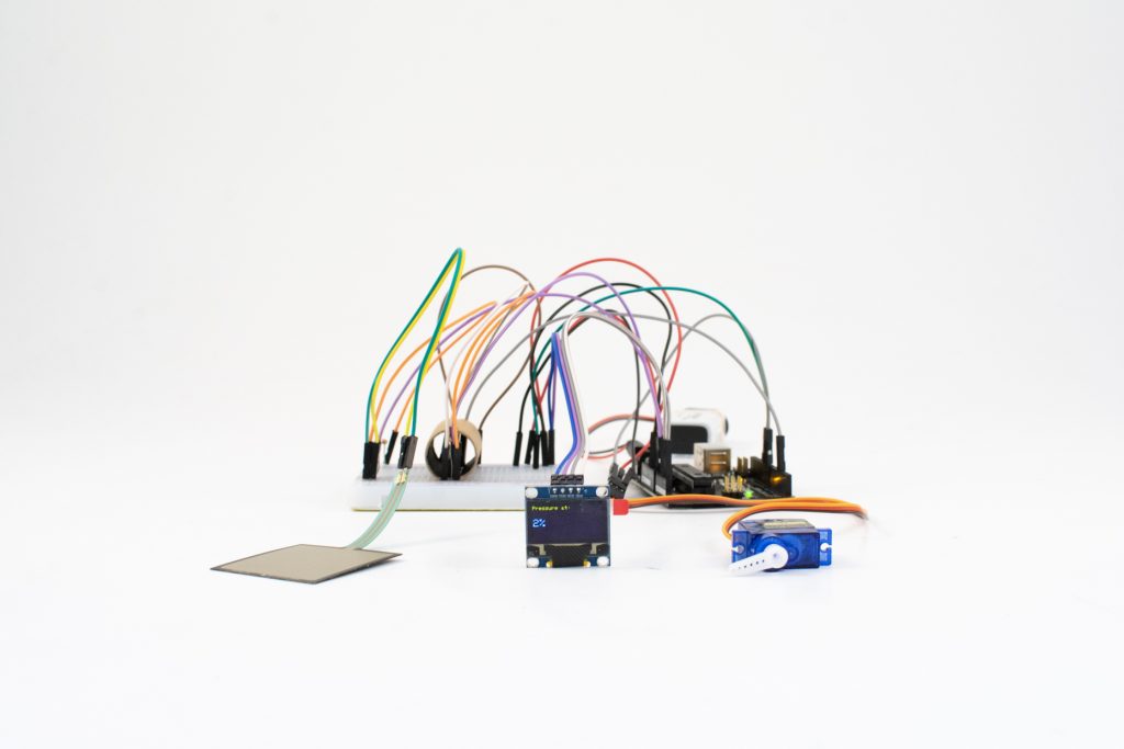
Pressure > IR > motor double transducer -
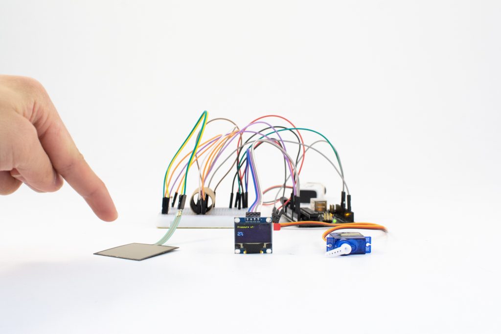
Pressure > IR > motor double transducer -
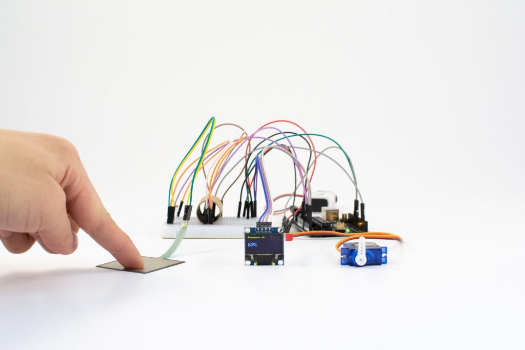
When pressure is applied to the FSR, the OLED display and servo motor update accordingly. -

A small cardboard tube with coated black interior shields the IR components from interference. -
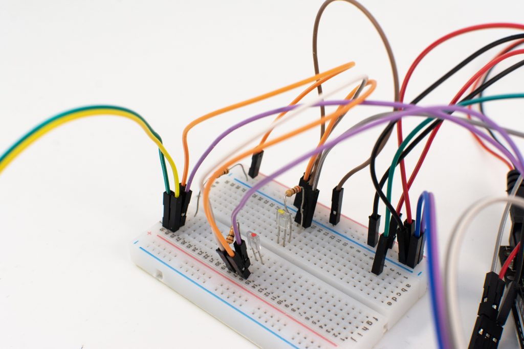
Cardboard shield removed, showing the IR transmitter and receiver situated in close proximity.
Description
This project transfers a pressure signal from a force-sensing resistor (FSR) pad to an infrared (IR) transmitter which is picked up by an IR receiver. The amount of IR light received is then used to move a servo motor, acting as a dial-like analog display, to a corresponding angle. Additionally, a digital OLED display shows the amount of pressure being applied to the pressure pad as a percentage.
ELI5: A pad is pressed and the force is displayed on a monitor. Two lights communicate with each other based on how hard you press and the lights tell the motor how much to move.
Progress images
-
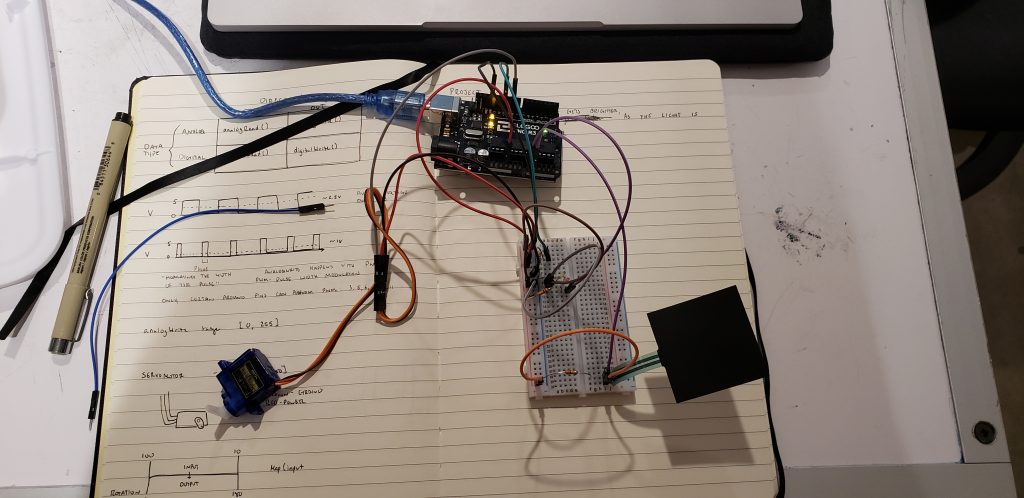
The sensor, IR, and motor working together. -
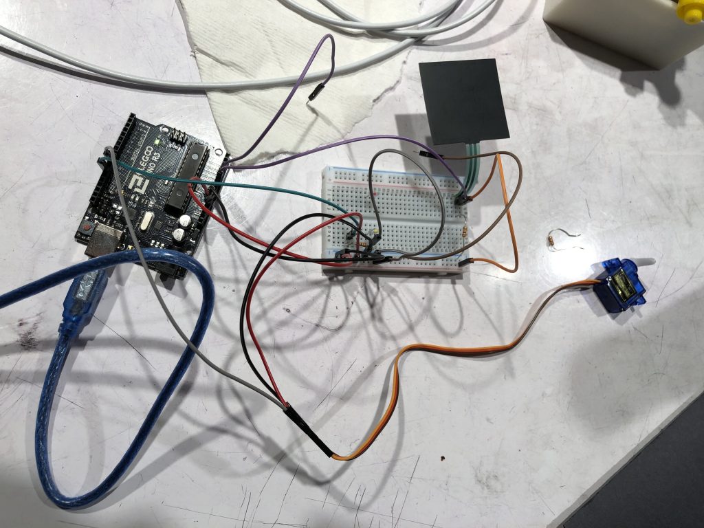
Preliminary wiring. Used to test functionality of IR components and perform readings of pressure outputted to Serial. -
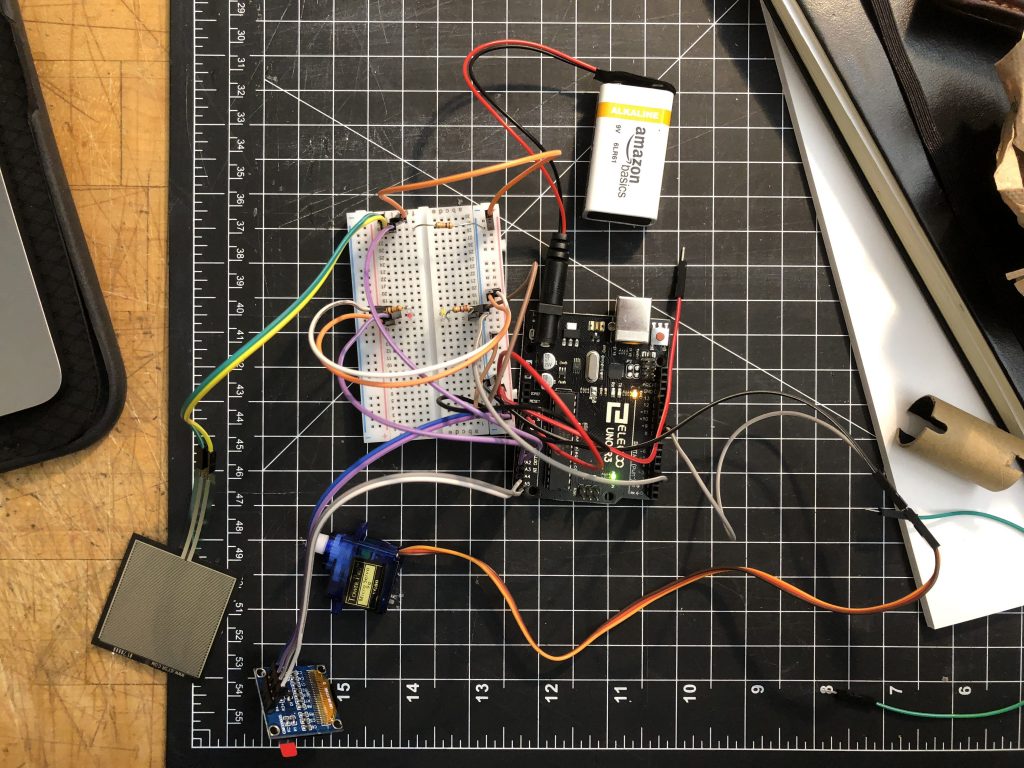
Final wiring. Note the repositioned IR components, FSR wiring extension, OLED display, and servo motor. IR shield removed to show parts.
Arranged from left to right: FSR pad, OLED display, servo motor. As more pressure is applied to the pad, the displayed percentage increases and the servo arm moves accordingly.
Schematic
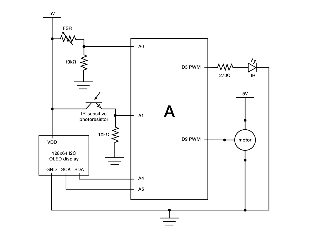
Code
/*
 * Project 1 - double transducer
 *
 * Implements a double transducer: pressure input from an FSR is transduced
 * to IR output, the level of which
 * is read with an IR receiver and transduced to the movement of a servo
 * motor serving as an analog display.
 * An OLED display also shows the relative percentage of pressure direct
 * from the FSR pressure input.
 *
 * A basic smoothing algorithm is implemented twice to reduce jitter in OLED
 * display output and servo motor
 * movement.
 *
 * Smoothing implementation adapted from David A. Mellis & Tom Igoe's
 * example at http://www.arduino.cc/en/Tutorial/Smoothing.
 *
 * I2C display implementation adapted from Limor Fried/Ladyada for
 * Adafruit Industries.
 */

#include <SPI.h>
#include <Wire.h>
#include <Adafruit_GFX.h>
#include <Adafruit_SSD1306.h>

#define SCREEN_WIDTH 128 // OLED display width, in pixels
#define SCREEN_HEIGHT 64 // OLED display height, in pixels

// Declaration for an SSD1306 display connected to I2C (SDA, SCL pins)
#define OLED_RESET     4 // Reset pin # (or -1 if sharing Arduino reset pin)
Adafruit_SSD1306 display(SCREEN_WIDTH, SCREEN_HEIGHT, &Wire, OLED_RESET);

#include <Servo.h>

// pin assignments
const int PRESSURE_PIN = A0;
const int IR_TRANSMIT = 3;
const int IR_RECEIVE = A1;
const int MOTOR_PIN = 9;
Servo motor1;

int force;
int ir_received;

// constants for sensor inputs and outputs
const int PRESSURE_MIN = 0;
const int PRESSURE_MAX = 1023;
const int LED_MIN = 0;
const int LED_MAX = 255;
const int MOTOR_MIN = 0;
const int MOTOR_MAX = 180;
const int IR_RECEIVE_MIN = 0;
const int IR_RECEIVE_MAX = 1023;

// setup for pressure display smoothing
const int pressureNumReadings = 15; // number of pressure readings over which to average
int pressureReadings[pressureNumReadings];
int pressureReadIndex = 0;
int pressureTotal = 0;
int pressureAverage = 0;

// setup for motor smoothing
const int motorNumReadings = 10; // number of motor inputs over which to average
int motorReadings[motorNumReadings];
int motorReadIndex = 0;
int motorTotal = 0;
int motorAverage = 0;
String percentage;

void setup() {
  // put your setup code here, to run once:
  pinMode(IR_TRANSMIT, OUTPUT);
  pinMode(IR_RECEIVE, INPUT);
  motor1.attach(MOTOR_PIN);
  motor1.write(0);

  // for motor smoothing; array setup
  for (int thisMotorReading = 0; thisMotorReading < motorNumReadings; thisMotorReading++) {
    motorReadings[thisMotorReading] = 0;
  }

  // for pressure display smoothing; array setup
  for (int thisPressureReading = 0; thisPressureReading < pressureNumReadings; thisPressureReading++) {
    pressureReadings[thisPressureReading] = 0;
  }

  Serial.begin(9600);


 // SSD1306_SWITCHCAPVCC = generate display voltage from 3.3V internally
  if(!display.begin(SSD1306_SWITCHCAPVCC, 0x3C)) { // Address 0x3C for 128x64
    Serial.println(F("SSD1306 allocation failed"));
    for(;;); // Don't proceed, loop forever
  }
}

void loop() {
  // put your main code here, to run repeatedly:
  force = analogRead(PRESSURE_PIN); // reading pressure level from FSR
  ir_received = analogRead(IR_RECEIVE);

  // IR LED transmits brightness according to pressure level on FSR
  analogWrite(IR_TRANSMIT, map(force, PRESSURE_MIN, PRESSURE_MAX, LED_MIN, LED_MAX));

  ir_received = analogRead(IR_RECEIVE); // IR receiver receives IR from IR LED relative to transmit brightness

  // smoothing to decrease jerking of servo motor - constant running average over 10 readings
  motorTotal = motorTotal - motorReadings[motorReadIndex];
  motorReadings[motorReadIndex] = map(ir_received, IR_RECEIVE_MIN, IR_RECEIVE_MAX, MOTOR_MIN, MOTOR_MAX); // mapping IR receiver range to motor movement range
  motorTotal = motorTotal + motorReadings[motorReadIndex];
  motorReadIndex = motorReadIndex + 1;

  if (motorReadIndex >= motorNumReadings) {
    motorReadIndex = 0;
  }

  // smoothing for display of pressure percentage on OLED panel - constant running average over 15 readings
  pressureTotal = pressureTotal - pressureReadings[pressureReadIndex];
  pressureReadings[pressureReadIndex] = map(force, PRESSURE_MIN, PRESSURE_MAX, 0, 100); // displaying pressure as percentage by mapping pressure readings
  pressureTotal = pressureTotal + pressureReadings[pressureReadIndex];
  pressureReadIndex = pressureReadIndex + 1;

  if (pressureReadIndex >= pressureNumReadings) {
    pressureReadIndex = 0;
  }

  // calculating average values for motor and OLED display output
  motorAverage = motorTotal / motorNumReadings;
  pressureAverage = pressureTotal / pressureNumReadings;
  delay(15);

  motor1.write(motorAverage);
  percentage = String(pressureAverage);
  Serial.println(percentage);
  testdrawchar(); // calls display function to show relative pressure as percentage on OLED display
}

// display function to show relative pressure as precentage on OLED display
void testdrawchar(void) {
  display.clearDisplay();
  display.setTextSize(1);
  display.setTextColor(WHITE);
  display.setCursor(0, 0);
  display.println("Pressure at: ");

  display.setTextSize(2);
  display.setTextColor(WHITE);
  display.setCursor(0, 24);
  display.println(percentage + "%");

  display.display();
}
Discussion
Yael~
I worked alone during the in class work period. At first I struggled a lot, especially due to being intimidated by how much I had to do on my own. I managed to get through the work session using Dan’s help as well as the internet. The use of many new parts at the same time was confusing and difficult for me, I ended up tackling it by integrating each new component separately. Some of the components were difficult because the rules for use contradicted previously learned material, such as the IF receiver – the longer pin had to be connected to ground. In the future I hope to expand my library of components and different tools that I will be able to use in more complex projects as well as my studio projects.
Ian:
Day 1 (4 hours)
When the project was handed off to me after the in-class work session, there were issues that had to be troubleshooted and corrected. First, while pressure readings from the FSR were being displayed in Serial output, since the IR receiver circuit lacked a resistor, values were all over the place and thus the servo motor (which derives it position from the amount of IR light received) was moving in an erratic, seemingly-random manner. Additionally, I altered the lines in code that accounted for the amount of IR light emitted from the LED to use analogWrite so that brightness would vary when plugged into a PWM pin on the Arduino. I also rewired the components on the board and to the Arduino so that the IR components would directly face each other. After some trial and error resulting in this setup, the next thing to tackle was constructing the code to be well-optimized for the application.
In theory, pressure values off the FSR can be directly applied to servo motor output using the map() function . However, given the requirement of a “double transducer,” the intermediate step of IR transmit and receive inevitably adds noise to the output – undesirable if one’s goal is to transduce one value to another. The first method applied to reduce noise was to shield the rearranged IR components with a cardboard tube, whose inside face I coated in black ink – the objective being to block as much interference from outside the system as possible. Secondly, I adapted Mellis and Igoe’s basic smoothing algorithm such that a running average of 10 IR receiver readings is written to change the servo’s position. Although this did not eliminate all jitter in the motor’s movement, it greatly reduced it to an acceptable (non-annoying) level. The number of values over which to average for was chosen as a balance between output stability and responsiveness (more values to average = more input lag).
Day 2 (1.5 hours)
As a “for-fun” bonus, a 128×64 OLED display was added to the project to display live pressure values as a percentage; the harder the FSR is pressed, the greater the percentage. Implementing an I2C digital display for the first time in a project presented a bit of a challenge since many implementations exist and are often specialized towards specific display components. Fortunately, I was able to ascertain and adapt the necessary function from the Adafruit I2C library in order to display text. Like the servo motor output, the displayed pressure percentage was also smoothed over a running average of 15 values (determined to be the best of both stability and responsiveness). Adding the display followed a sort of theme with the project as a whole – taking advantage of FOSS resources to wire all the components as well as integrate them in code.
Days 3 & 4 (2.5 hours)
After the project was completed and presented in class, I photographed it using a lighting cube in my design studio, post-processed the images in Lightroom, and made a wiring diagram in Illustrator describing the electronics. Given more time, possible refinements include soldering components together and creating a housing to yield a higher degree of refinement. An intriguing extension includes testing different, more advanced smoothing algorithms in order to remove any discernible jitter in the outputs.
Created by Benni of Tinker-Fun
This button features a rotary encoder with programmable interactions for shortcuts to be used in conjunction with drawing applications (Autodesk Sketchbook, others). With interactions such as rotating the knob and single- or double-pressing it like a button, features like rotating a canvas, changing brush size, swapping tools, and undoing options are more easily accessible. This eliminates the complexity of a keyboard so that the user can focus on drawing, keeping a pen or stylus in one hand and manipulating the workspace through the shortcut button with another.
Rotary encoders have long been used as a means of control in human-computer interactions, including the scroll wheel on a mouse and a control dial on a digital camera. In recent years, products such as the Microsoft Surface Dial (which inspired this project) have surfaced on the market to accomplish the kinds of tasks the “Teensy USB Shortcut Button” is designed to perform. Whereas the Surface Dial is a more refined product with excellent build quality and finishes, it also has an MSRP of $100 and is proprietary to the MS Surface line of products. In contrast, this project costs a fraction of $100 to assemble, is open-source, and can be configured across a wide variety of systems.

The most immediate improvement to the project after fit and finish would be to integrate wireless function. Since it communicates over USB, a possibility would be to add a wireless USB chip that pairs with a receiver or to switch the protocol to Bluetooth. Other ideas of possible interest include tying LED color, brightness, and position to the function currently in use and adding greater nuance in control with directional nudging (think a d-pad) or movement of the control itself.
The reason I chose this project is that possibilities for rotary encoders, in conjunction with physical and software controls, open a wide range of innovative new interfaces. For example, smartwatches such as the Apple Watch and Samsung Galaxy Watch use different types of rotary encoders (the Digital Crown and dial, respectively) in combinations with other physical and software controls in order to solve the problem of interacting with content on such a small display. Other possible interactions include building larger, more tactile knobs that interface with computers or smartphones, improving efficiency in specialized tasks or accessibility for those with limited motor function. With a well-crafted hardware control in conjunction with thoughtfully-designed software, the relationship of directly manipulating something digital with a tactile knob has potential to increase the satisfaction of the interaction.
]]>