Double transducer- from vibration to color
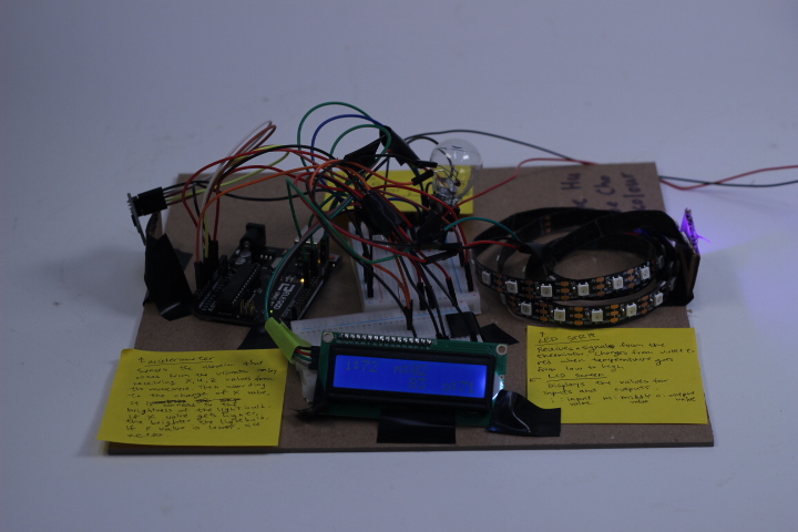
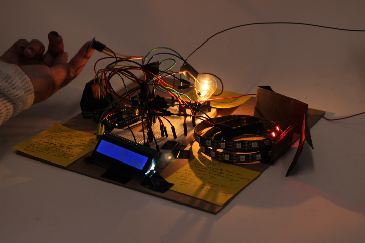
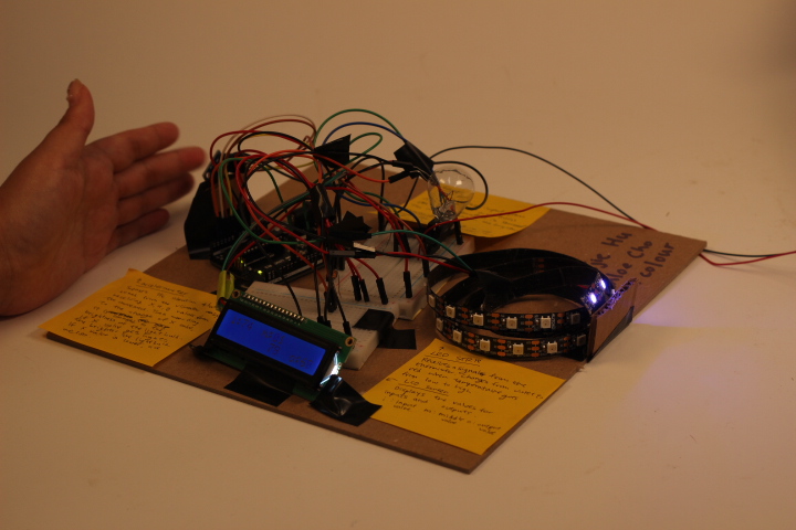
Overview of our double transducer
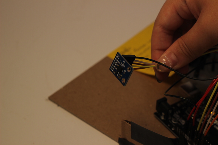
accelerometer; senses the vibration motor
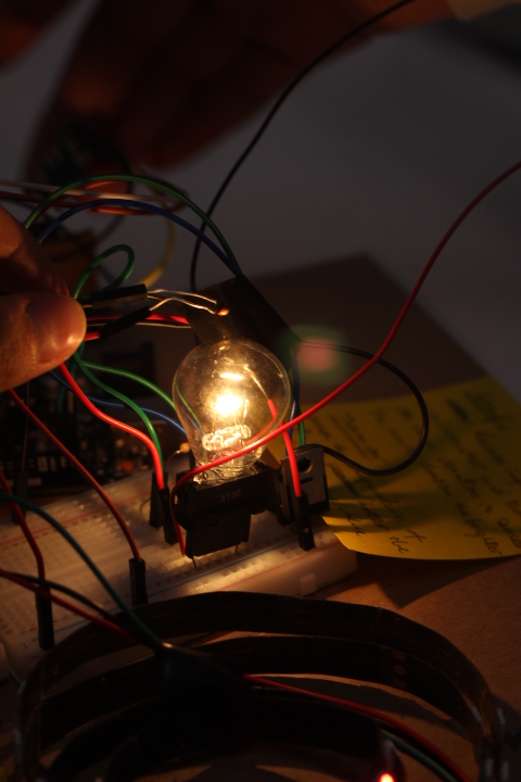
Thermistor and the light bulb; transduces the vibration in to heat
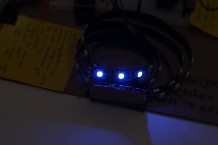
LED; changes from purple to red depending on the heat level
Static State; the LED is purple

Heat generated based on the level vibration; the LED is now red
Description –
We created a double transducer that takes in vibration signals and turns it into lamp brightness, which will then affect the thermistor and leads to color change from purple to red.
When the vibration gets higher, the lamp will be brighter, and it leads to temperature raising up around the thermistor; the thermistor will then send signals to the LED strip to change color from purple to red. When vibration stops, lamp turns off, temperature drops and the color goes back to red.
Process Images –
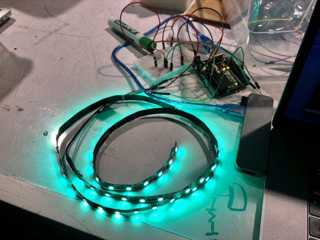
getting the LED strip working
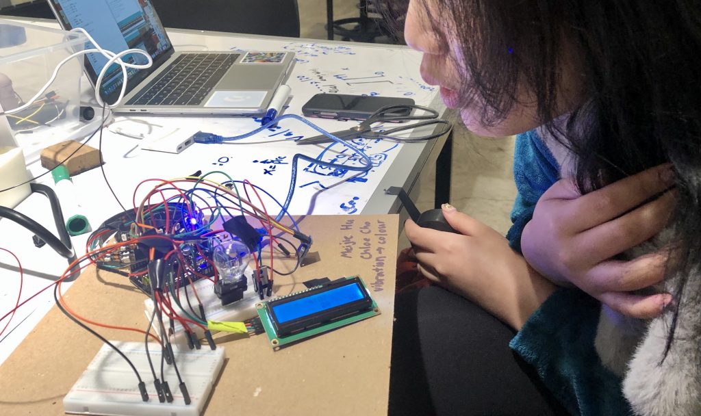
Combine two parts – Chloe blowing thermistor to cool it down
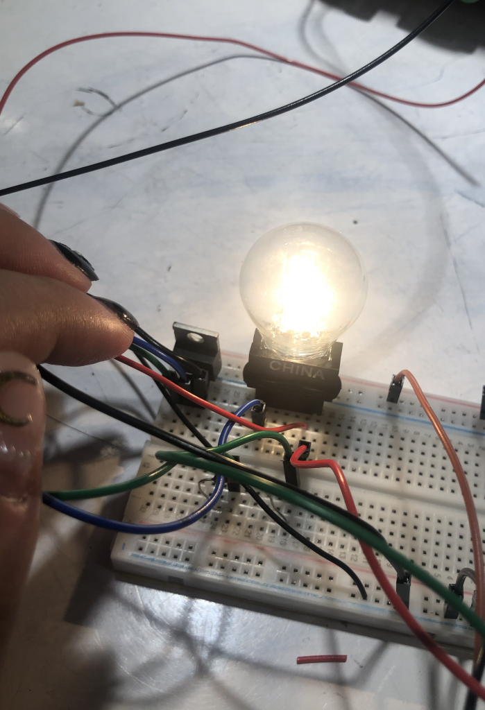
Getting the lamp to work
Discussion –
Overall, the transducers we made are relatively easy to implement. Since we mainly need to deal with codes and the wiring is something similar to what we learnt in class, it is much simpler than those groups requires some physics knowledge. However, there are still some challenges during the process, especially in finding the right components that fit together. As a person who really don’t like reading instruction manuals (yes, no shame), this project taught me a lot about reading the labels and looking up manuals online to find out the correct ways to connect components together. I got a lot of instructor help to figure out the correct components and correct schematics hopefully next time I can improve a bit by being able to read the manuals figure out the wiring on my own.
The difficult part was struggling with the power source. Our laptop could not accept the transistor when it is connected, so we had to upload our code every time to the arduino board and unplug it, which made it hard to notice the change to the physical part whenever the code was updated. Also using the 12 volt power source was something that we never tried before, however, it was successful. It was hard to wire the lamp, transistor, and the power source together, yet with some help from our professor, it all made sense to us eventually. The accelerometer was the easiest part. We thought using the x value of the accelerometer to convert it into heat would be the best because we realized that the x value was the most-changing value after a few test plotting. Setting the range for x value was the hardest part. Depending on the range, the lamp could be too sensitive or too dull. However, we wrote a separate piece of code to test the ranges and then all we had left was to map it so that the x value will be on the same range as the lamp.
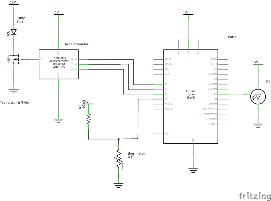
Schematics –
Code submission –
/*
Double transducer-vibration to color
A double transducer that exchanges the sensed vibration into color.
The vibration is sensed through an accelerometer, then the lightbulb is generated, the thermistor senses it, then the LED changes its color based on the strength.
Based on the strength of the vibration, the color will change from violet to red.
*/

#include <PololuLedStrip.h>
#include <Wire.h>
#include <LiquidCrystal_I2C.h>

/*-------LED------*/
// pin for LED strip
PololuLedStrip<7> ledStrip;
// number of LED on the strip
#define LED_COUNT 60
//an array of colors that is the length of LED_COUNT
rgb_color colors[LED_COUNT];

//pin for lightbulb
const int LIGHTPIN = 11;
/*-----accelerometer----*/
const int XPIN = A0;
const int YPIN = A1;
const int ZPIN = A2;

/*-------Thermistor------*/
const int TEMPPIN = A3;
int temVal;
//room temperature boundary
int UPBOUND = 500;
//hot temperature boundary
int LOWBOUND = 420;

/* Create an LCD display object called "screen" with I2C address 0x27
which is 16 columns wide and 2 rows tall. You can use any name you'd like. */
LiquidCrystal_I2C screen(0x27, 16, 2);

int x = 123;
//record old accelerometer value
int oldX;
int xVal;

byte frowny[] = {
B00000,
B11011,
B11011,
B00000,
B00000,
B01110,
B10001,
B00000
};

void setup() {
// pins for lightbulb and accelerometer
pinMode (LIGHTPIN, OUTPUT);
pinMode(XPIN, INPUT);
pinMode(YPIN, INPUT);
pinMode(ZPIN, INPUT);

// initialize the screen (only need to do this once)
pinMode(TEMPPIN, INPUT);

Serial.begin(9600);

xVal = analogRead(XPIN);

// initialize the screen (only need to do this once)
screen.init();

// turn on the backlight to start
screen.backlight();

delay(1000);
//print constant letters on screen
screen.clear();
screen.home();
screen.print("i:");

screen.setCursor(6, 0);
screen.print("m:");

screen.setCursor(12, 1);
screen.print("o:");
}

void loop() {
// put your main code here, to run repeatedly:

//get the temperature;
temVal = analogRead(TEMPPIN);
Serial.println(temVal);

//compares the difference between the old accelerometer x value and the new value
oldX = xVal;
xVal = analogRead(XPIN);
int dif = abs(oldX - xVal);
int lightVal = map(dif, 0, 520, 0, 255);

//light is off in a static range, else it is on in a range
if ( dif > 10) {
analogWrite(LIGHTPIN, dif);
}
else {
analogWrite (LIGHTPIN, 0);
}

if (temVal >= UPBOUND) {
temVal = UPBOUND;
}
//determine upper bound
if (temVal <= LOWBOUND) {
temVal = LOWBOUND;
}

//map it to the color range
int temMap = map(temVal, LOWBOUND, UPBOUND, 0, 1040);
int h = (temMap >> 2) % 360;

//turn on LED 57,58,59
for (uint16_t i = 57; i < LED_COUNT; i++)
{
colors[i] = hsvToRgb(h, 255, 255);
}

// Write the colors to the LED strip.
ledStrip.write(colors, LED_COUNT);

delay(50);

// just count up to show x changing (the rest of the text will remain untouched)
screen.setCursor(2, 0);
screen.print(map(xVal, 0, 525, 0, 99));

screen.setCursor(8, 0);
screen.print(map(lightVal, 0, 255, 0, 99));

screen.setCursor(8, 1);
screen.print(map(temVal, LOWBOUND, 515, 0, 99));

screen.setCursor(14, 1);
screen.print(map(h, 0, 359, 0, 99));
delay(200);
}

// hsv to rgb converter
rgb_color hsvToRgb(uint16_t h, uint8_t s, uint8_t v)
{
uint8_t f = (h % 60) * 255 / 60;
uint8_t p = (255 - s) * (uint16_t)v / 255;
uint8_t q = (255 - f * (uint16_t)s / 255) * (uint16_t)v / 255;
uint8_t t = (255 - (255 - f) * (uint16_t)s / 255) * (uint16_t)v / 255;
uint8_t r = 0, g = 0, b = 0;
switch ((h / 60) % 6) {
case 0: r = v; g = t; b = p; break;
case 1: r = q; g = v; b = p; break;
case 2: r = p; g = v; b = t; break;
case 3: r = p; g = q; b = v; break;
case 4: r = t; g = p; b = v; break;
case 5: r = v; g = p; b = q; break;
}
return rgb_color(r, g, b);
}
Comments are closed.