
WalkProp
OvervIew
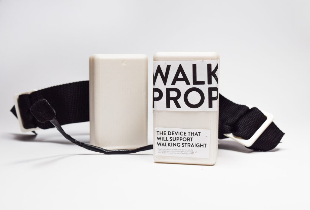
WalkProp is an assistive device that will support your feet “walking straight” or parallel from each other.
How the device works (you can hear the vibration when the right foot is not parallel to the left foot)
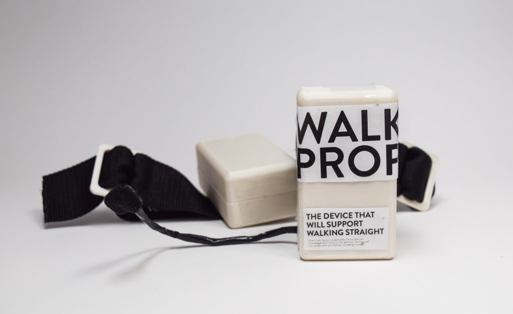
Overall image
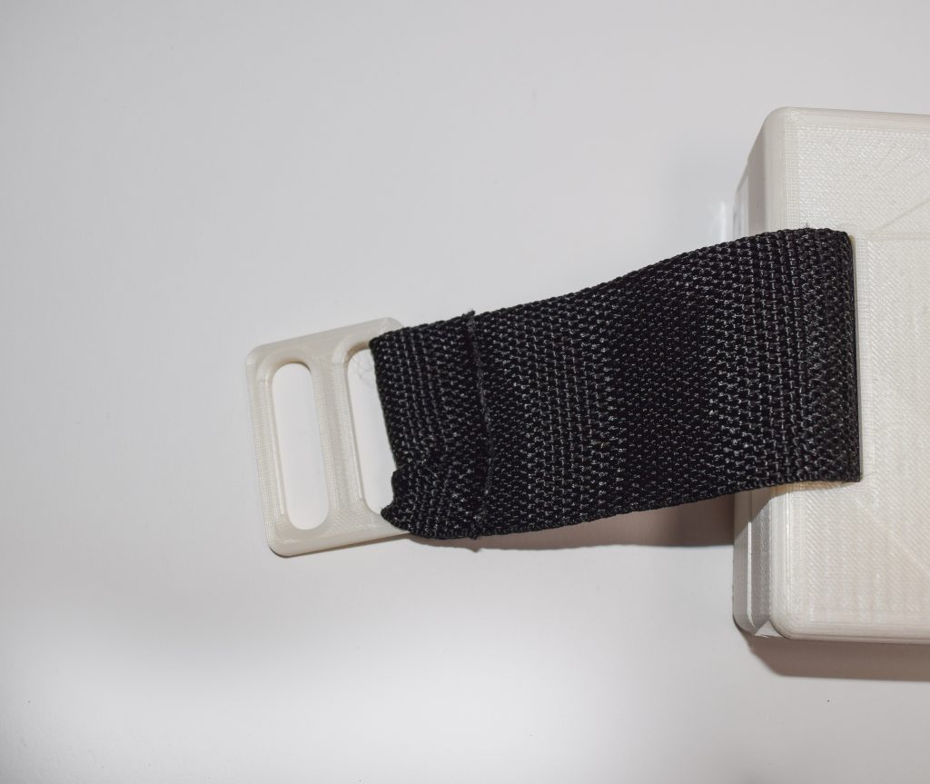
3D printed strap buckle
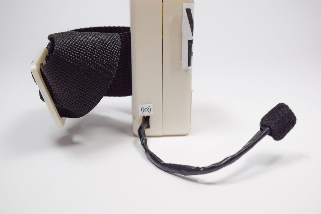
Vibration motor and its packaging design on device
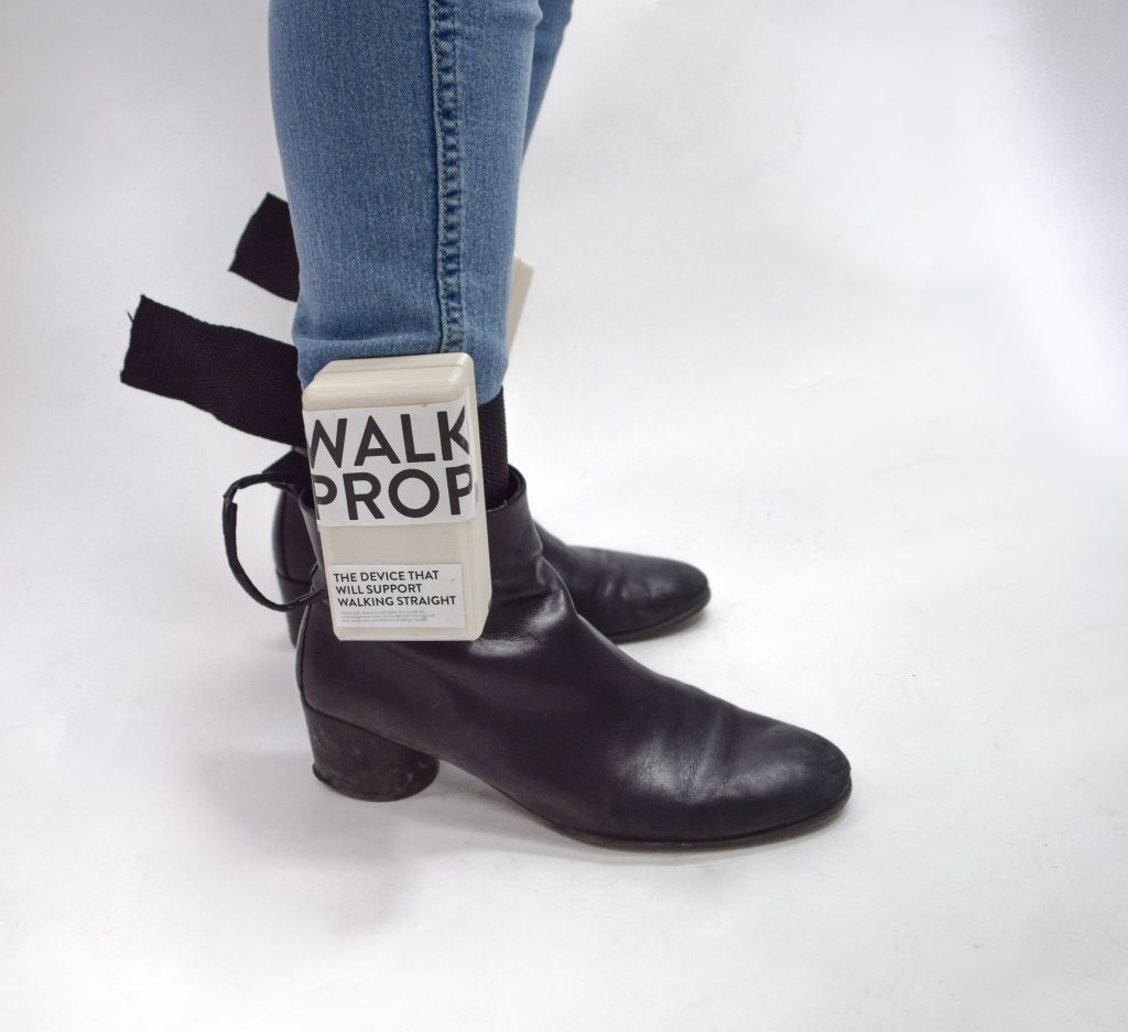
Wearing the device
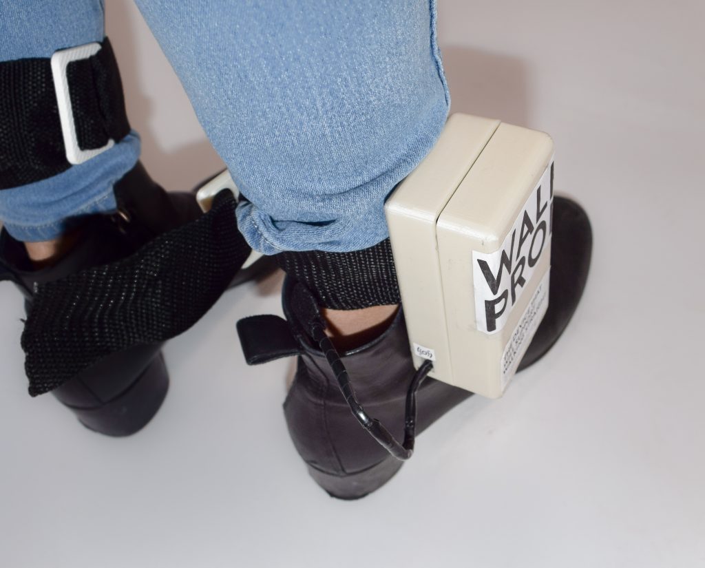
How the vibration motor would be placed inside a shoe
Process images and review
These are two of the major decision points in my progress that impacted the end result of my project.
- The Arduino Uno and Arduino Pro Mini Situation:
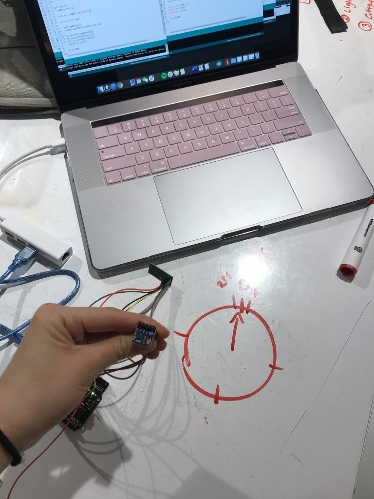
The magnetometer acts as a compass
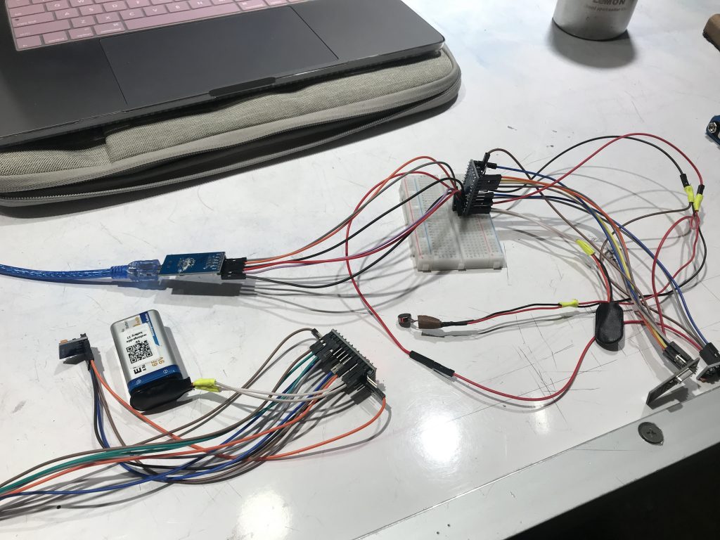
I started this project with wiring two GY 271 magnetometers and my plan was to code for the magnetometers so that they would read the direction of where they were turned (on one plane) just like a compass. From this, I learned that to communicate between the two magnetometers, the more effective option would be to use transmitters and to separate them onto two Arduinos.
Prototype of device with magnetometer, transmitter and vibration motor
This prompted me to use the smaller Arduino Pro Minis to replace the larger Arduino Uno, hoping to make my device more comfortable to wear and inconspicuous on the body. I wired up the Arduino Pro Minis and was able to send my code to it, however, the feedback was jumbled and I could not receive the data of the left and right magnetometers that I would have been able see from the Arduino Uno.
Replacing the Arduino Uno with the Arduino Pro Mini
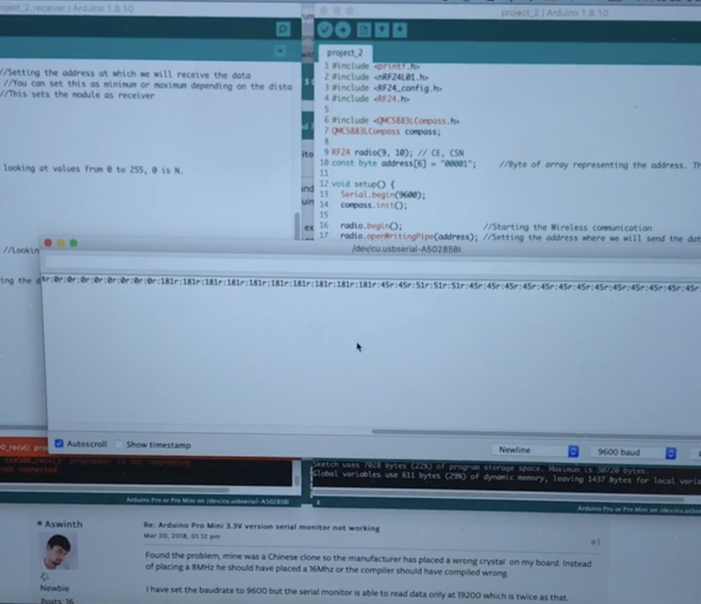
The screen shows that it is only displaying the receiving transmitter’s data (right foot) and not the transmitting one (left foot)
I spend a significant amount of time making this change to a smaller device so I tried multiple ways to resolve the problem. I asked multiple people about how I could use the Arduino Pro Mini and searched for online solutions. However, the left foot’s transmitter would not display its data. I doubled checked my wiring and replaced wires in case that that was the issue, yet the result was the same. This was the point where I decided that in order for my device to work in our limited time, I should switch back to the larger Arduino Uno.
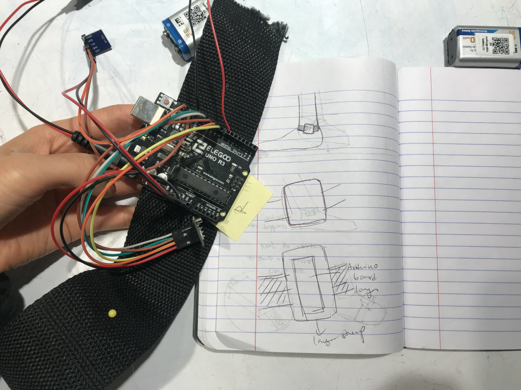
Using the Arduino Uno for the final deliverable and sketching ideas for the packaging
Working with a larger device base, I tried to condense the size as much as possible with taping Arduino components as tightly as possible together. I drew ideas for how I could package my device and I decided to 3D print a custom sized rectangular prism with rounded corners and edges to be more aesthetically pleasing (I wanted to create a minimalistic style) and user friendly to touch.
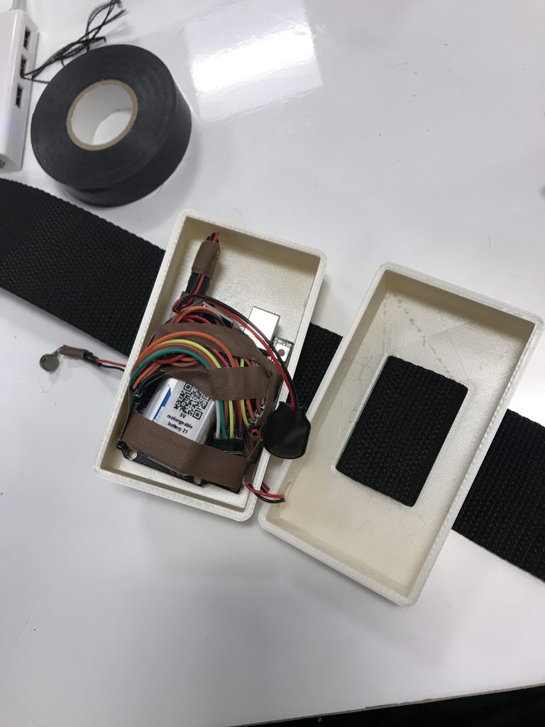
Condensing the wiring and interior as much as possible with tape to place inside its packaging
2. Changing the Code:
While I was creating the packaging for my device, I realized for the magnetometers that were connected to the Arduino Unos, the data that was being displayed was very noisy and fluctuated significantly. Even though the range of data that is coming from the magnetometers was suppose to be from 0 to 255, this was not the case in reality. This led to my second major change, where I looked for patterns in the code and calibrated the device so that the right foot (since my right foot was the one that normally doesn’t walk straight forward) needed only to be parallel to the left foot. In my code, I looked for the changes in numbers when my right foot strayed from being parallel and I used the this to signal when the vibration motors should be activated. I also included a line of code (with help from the TA) that helped reduce the noise and fluctuation of the data being received from the magnetometers to increase the accuracy of the readings.
Discussion
After completing this project, I am satisfied with what I have accomplished because I was able to learn and explore new Arduino devices that I did not know how to use before, such as the transmitter and Arduino Pro Mini. Also, I experienced the process of creating something that could be potentially used in the real world to help myself or others. I was also happy that I was able to move on with the issue over the Arduino Mini Pro and solve the situation quickly by using the Arduino Uno. Thinking back, if I dwelled on this, I would not have been able to spend time on the exterior design. Furthermore, I realized that it is much more difficult to create a useable device than I expected. If it was already so demanding to create an assistive device just for myself, it would be multiple times more difficult to create a tool for everyone. I also learned that there can also be many different obstacles that you cannot anticipate. Through this project, I learned to used the resources and knowledge that I have to adapt to situations and modify the final product according to these unexpected troubles. I think this is very relevant for the future in real world situations where these situations can happen much more often and I would need to quickly adapt and learn on the spot to face these troubles in order to find a solution.
Specifically in the making of my device. I realized that much of how to solve Arduino coding problems is to search online and learn from example codes. Before, I thought that people who were experts in Arduino would simply know what the problem is with just by looking at the code because they knew the C language, however, when I asked them about various issues I was having, they also went through the same pattern of searching online and learning on the go. This really helped me find methods on how to solve problems myself for the future. Furthermore, I was surprised by how enjoyable 3D printings was. I was not very familiar with 3D printing before and from this project, it suddenly hit me how magical and easy this can be – I simply model anything I want and I can print it in real life. Next time, I want to try to experiment with more complex exterior packaging for devices and also try different laser cutting techniques (such as laser cutting patterns on wood to allow it to bend).
I think this project really incited my interest for wearable technology. For future projects, I would want to explore e-textiles including Adafruit boards, flexible technology, and more. This would compliment my design background well.
Most people that gave feedback for my project mentioned that is was quite large and I was able to explain the reason behind this. They also enjoyed how minimalistic it was and this made me happy with my decision on how I chose to design the exterior even with its large size. If I were to further develop this project, I would spend more time investigating how I could make the device more compact (perhaps purchasing another type of board and using smaller portable batteries).
My classmates said:
“A bit bulky, but you covered why.”
“It is a little too large for what it is supposed to do”
“The design is clean and polished. The size is a bit large”
“The box is minimalist and simple”
“The project looks very clean and easy to put on”
One comment was especially interesting to me where they said that,
“you can definitely expand the product to solve all different ways of walking ‘wrong’, if you detect angles and whatnot.”
I thought that this very interesting and I think it would be a great way for me to expand my device from a more individualized use to a public one. This way, I would also be able to learn to use other Arduino components that I could use to help correct people’s walking.
Technical Information
Schematic
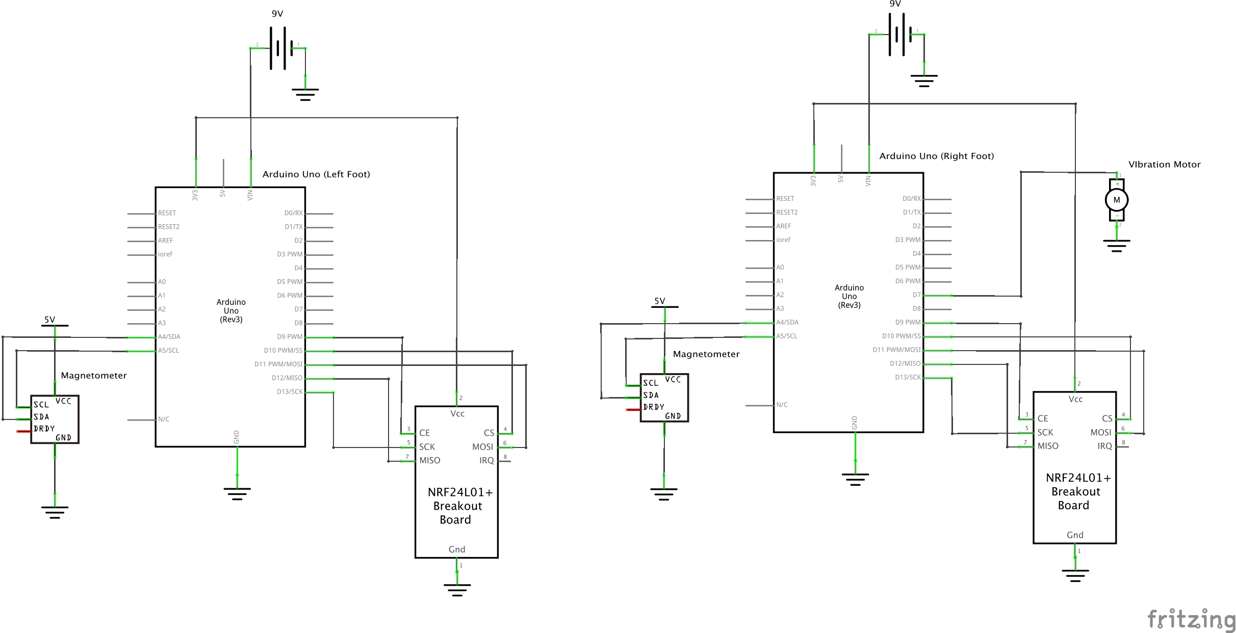
Schematic for left and right foot devices
Code
Left foot code (Transmitter)
/*
   Title: WalkProp
   Author: Patricia Yu

   Description: This the code for the left foot of my device (the transmitting transceiver).
    There are two magnetometers that measure compass direction and translates this data into a number
   range from 0 to 255 (0 signifying North, however, this was not always the case as
   there was a lot of noise in the data and the transmitting data did not follow this rule).
   For the left foot's device, the transceiver RF24 will then send the data from the magnetometer
   to the receiving transceiver on the right foot. The receiving end will compare this sent data to
   its own compass' data (on the right foot) and if it is within a certain range (this limit number is gotten from
   me turning the right foot's device and seeing a pattern within the differences fo the numbers
   seeing a pattern between the right and left foot's magnetometer's data), then the feet are parallel.
   Or else, it will signify that the feet are not parallel and the vibration motor on the right foot will
   vibrate to alert the user.
  _____________________________________________________

     Pin mapping:
   pin   | mode   | description
   ------|--------|------------
   09     output    nRF24L01 Transceiver
   10     output    nRF24L01 Transceiver
   11     output    nRF24L01 Transceiver
   12     output    nRF24L01 Transceiver
   13     output    nRF24L01 Transceiver
   SDA/SCL input    Magnetometer


  _____________________________________________________

  Credits:

  Magnotometer/Compass code library:
  QMC5883LCompass by MRPrograms

  nRF24L01 Transceiver code library:
  RF24 by TMRh20

  Transceiver wiring/code help:
  https://create.arduino.cc/projecthub/muhammad-aqib/nrf24l01-interfacing-with-arduino-wireless-communication-0c13d4

  Professor Zacharias for helping with figuring out how to set the magnetometer to be a compass
  TA Harshine for helping me with the code to reduce noise from the compass
*/

//Magnetometer code from library:
#include <QMC5883LCompass.h>
QMC5883LCompass compass;

//RF24 code from library:
#include <printf.h>
#include <nRF24L01.h>
#include <RF24_config.h>
#include <RF24.h>

RF24 radio(9, 10); // CE, CSN
const byte address[6] = "00001";     //Byte of array representing the address. This is the address where we will send the data. This should be same on the receiving side.
byte t = 0;

void setup() {
  Serial.begin(9600);
  compass.init(); //setup for magnetometer

  //setup for transceiver:
  radio.begin();                  //Starting the Wireless communication
  radio.openWritingPipe(address); //Setting the address where we will send the data
  radio.setPALevel(RF24_PA_HIGH);  //You can set it as minimum or maximum depending on the distance between the transmitter and receiver.
  radio.stopListening();          //This sets the module as transmitter

}
void loop() {
  // Read compass values in directions looking at values from 0 to 255, 0 is suppose to be N.
  compass.read();
  t = (.9) * (t) + (0.1) * (compass.getAzimuth()); // to reduce noise when receiving compass data from Transmitter
  radio.write(&t, sizeof(t));  //Sending the message to receiver
  delay(5);
}
Right foot code (Receiver)
/*
   Title: WalkProp
   Author: Patricia Yu

   Description: This the code for the right foot of my device (the receiving transceiver).
   There are two magnetometers that measure compass direction and translates this data into a number
   range from 0 to 255 (0 signifying North, however, this was not always the case as
   there was a lot of noise in the data and the transmitting data did not follow this rule).
   For the right foot's device, the transceiver RF24 fromt he left foot will  send the data from the magnetometer
   to the receiving transceiver on the right foot. The receiving end will compare this sent data to
   its own compass' data (on the right foot) and if it is within a certain range (this limit number is gotten from
   me turning the right foot's device and seeing a pattern within the differences fo the numbers
   seeing a pattern between the right and left foot's magnetometer's data), then the feet are parallel. Or else, it will signify that
   the feet are not parallel and the vibration motor on the right foot will vibrate to alert the user.
  _____________________________________________________

     Pin mapping:
   pin   | mode   | description
   ------|--------|------------
   09     output    nRF24L01 Transceiver
   10     output    nRF24L01 Transceiver
   11     output    nRF24L01 Transceiver
   12     output    nRF24L01 Transceiver
   13     output    nRF24L01 Transceiver
   SDA/SCL input    Magnetometer
   07     output    vibration motor
  _____________________________________________________

  Credits:

  Magnotometer/Compass code library:
  QMC5883LCompass by MRPrograms

  nRF24L01 Transceiver code library:
  RF24 by TMRh20

  Transceiver wiring/code help:
  https://create.arduino.cc/projecthub/muhammad-aqib/nrf24l01-interfacing-with-arduino-wireless-communication-0c13d4

  Professor Zacharias for helping with figuring out how to set the magnetometer to be a compass

*/

//Magnetometer code from library:
#include <QMC5883LCompass.h>
QMC5883LCompass compass;

//RF24 code from library:
#include <printf.h>
#include <nRF24L01.h>
#include <RF24_config.h>
#include <RF24.h>

RF24 radio(9, 10); // CE, CSN
const byte address[6] = "00001";

int angle; //angle is the number that will be used to set a range for when the vibration motor is activated
const int VIBRATE = 7; // vibration motor pin

void setup() {
  Serial.begin(9600);
  compass.init(); //setup for magnetometer
  pinMode(VIBRATE, OUTPUT);

  //setup for transceiver:
  radio.begin();
  radio.openReadingPipe(0, address);   //Setting the address at which we will receive the data
  radio.setPALevel(RF24_PA_HIGH);       //You can set this as minimum or maximum depending on the distance between the transmitter and receiver.
  radio.startListening();              //This sets the module as receiver
}
void loop() {
  // Read compass values in directions looking at values from 0 to 255, 0 is suppose to be N.
  compass.read();
  delay(5);
  byte r = compass.getAzimuth(); //compass data from Receiver
  Serial.print("r:");
  Serial.print(r);
  delay (500);

  if (radio.available())              //Looking for the data.
  {
    int t;
    radio.read(&t, sizeof(t)); //Reading the data from Transmitter
    Serial.print(" t:");
    Serial.println(t);

    // using the difference between the angles of magnetometers to detect when angles of feet are changed to indicate if they are parallel or not
    angle = (t - r);
    angle = abs(angle);
  }

  // if the angle between the two devices are over a certain calibrated debree, the vibration motor will signal the user to adjust their feet position
  if (angle >= 70 ) {
    digitalWrite(VIBRATE, HIGH);
  }
  else {
    digitalWrite(VIBRATE, LOW);
  }
}
Comments are closed.