


This particular assistive device was developed as the final project for physical computing where 3 students worked closely with our client, Elaine Houston, to create something that would improve their ability to complete daily tasks. Starting off this process process with an interview, we were able to get a sense of what types of devices would suit Elaine’s needs best. More information on this interview process can be found in our interview documentation page. After narrowing down our list of devices we developed a prototype that we then presented to Elaine for initial feedback. With this feedback as well as continual input from Elaine throughout the process, we arrived at this final button-activated blinds operator design.
What We Built
This device allows Elaine to raise and lower her blinds at the push of a button. Incorporating Elaine’s dog Oak into the final design, once Oak pushes the button, the blinds operator will rotate the curtain chain in a certain direction to raise or lower the curtains until they are fully open or closed. The direction of the spinning is dependent upon whether the curtains need to be raised or lowered. Finally, while the blinds are in the process of raising or lowering, the button is disabled.
Here’s a gif of the blinds operator working. While this video is faster than real time, if you look closely, you can see the rotation of the motor arm slow start and stop feature.
Details
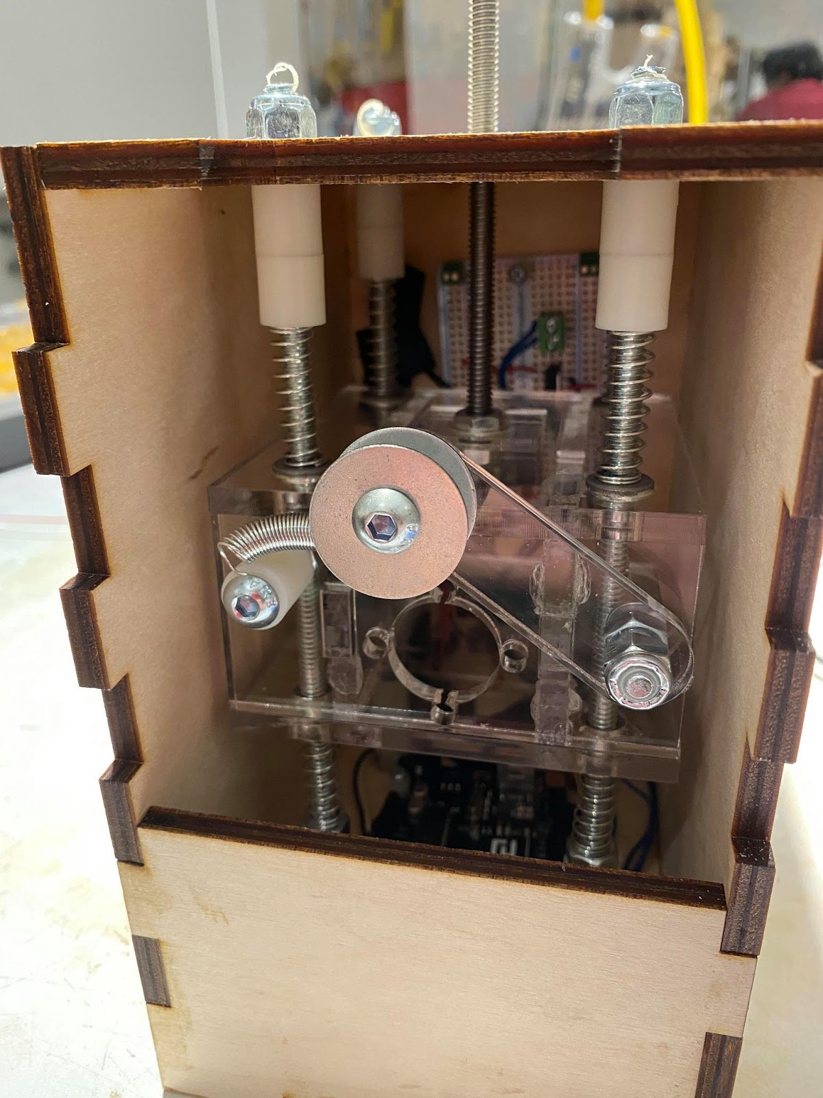
The inner compartment of the blinds. Pictured is the primary tensioning mechanism consisting of the threaded rod in the center of the motor mount, the acrylic motor mount, and the secondary tensioning mechanism consisting of the spring connected to the link. This secondary tensioning mechanism is used to keep tension on the ball chain once it motor mount is adjusted to the correct height with the primary tensioning mechanism.

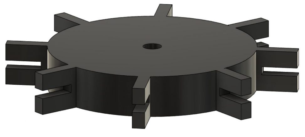
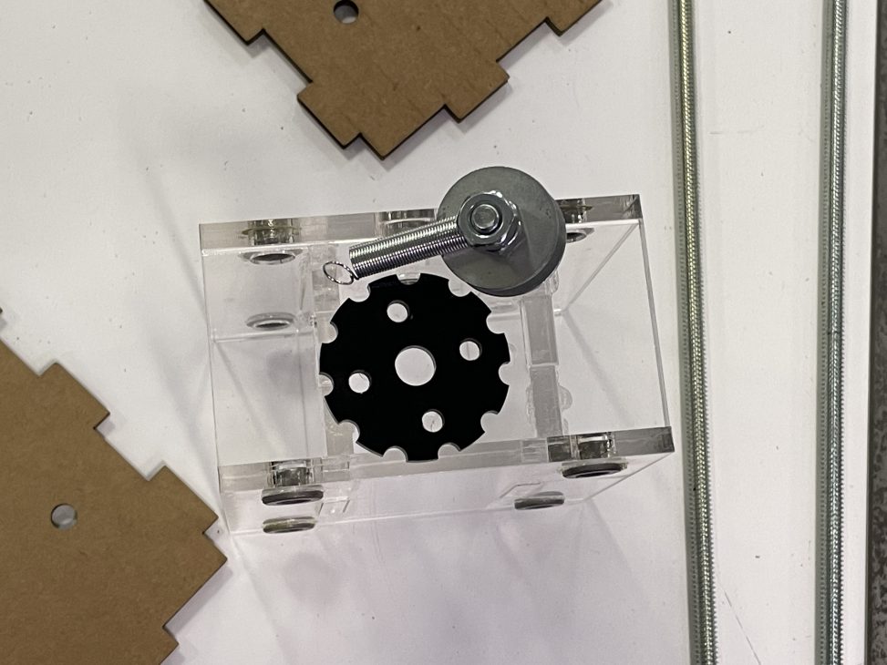
The laser-cut gear mechanism plus the motor mount which will interface with the ball-chain and turn it.
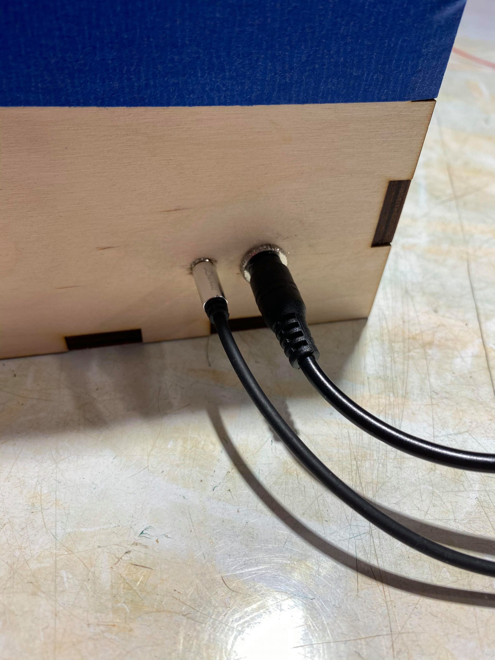
Outside view of the power jack adapter for the power supply and the barrel jack adapter for the button.
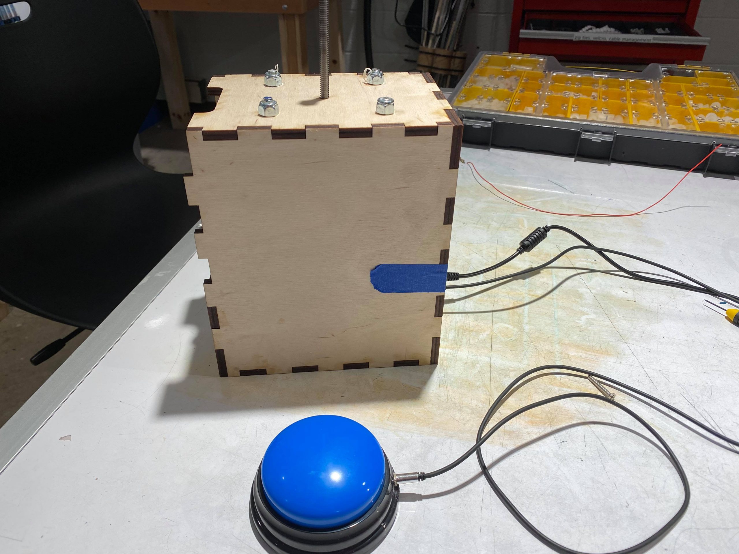
A side-angle-view of the entire device. The knob at the top (not pictured) controls the position of the inner motor mount by turning the threaded rod.
Narrative Use Description
Elaine is relaxing at home and doing some work at her desk when she realizes that the blinds are open. Seeking to reduce the glare from the sunlight, Elaine would like to close the blinds. Since her aide is not there at the moment, she calls for Oak, her service dog who is always nearby. Elaine gives Oak the command to press the large button by her desk, and Oak complies quickly, understanding very easily where he should press. This button-press triggers the motor attached to the ball-chain on the blinds, slowly lowering the canvas to cover the harsh sunlight.
The next morning is a beautiful day, and Elaine would like her blinds open again. Giving Oak the command again, Oak walks over to press the button as Elaine sits back and watches her blinds open up again.
How we got here (prototype and process)
Eric
Button Switch
I started my portion of the blinds opener by prototyping the question:
- How would the opener best be operated by Oak?
We settled on a push button as the switch that Oak would press to activate the blinds opener. The physical computing lab had small arcade pushbuttons, which I decided to use as a base for a larger 3D printed adapter to make the button bigger, and therefore easier for Oak to press.
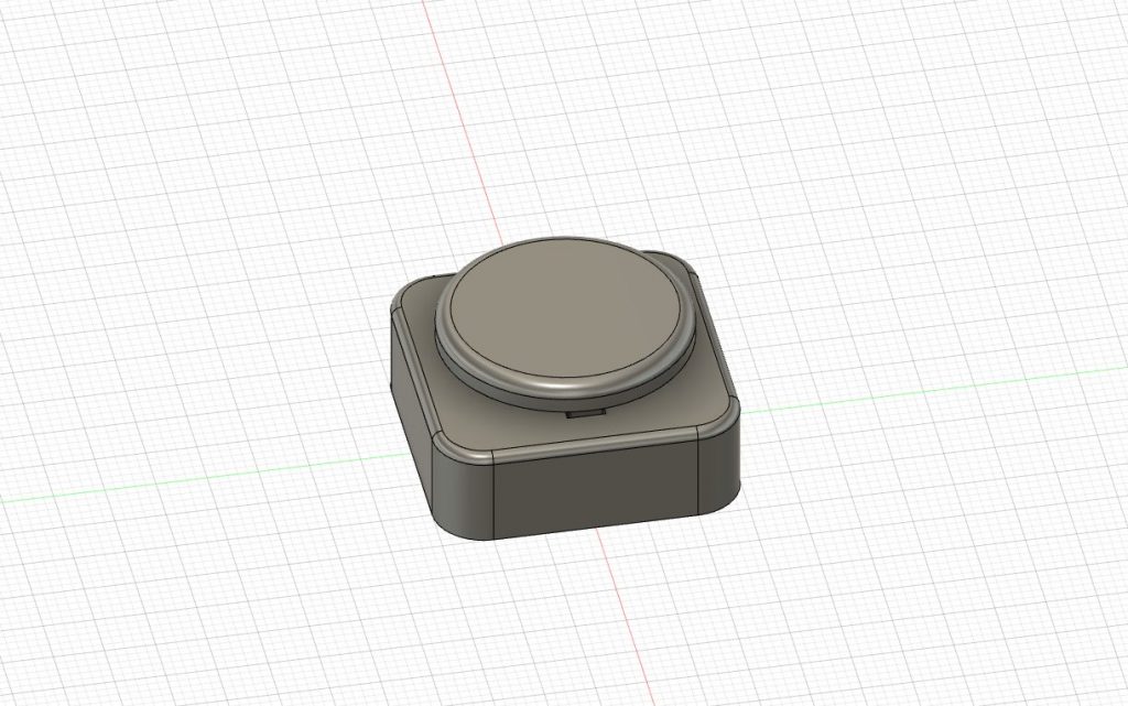
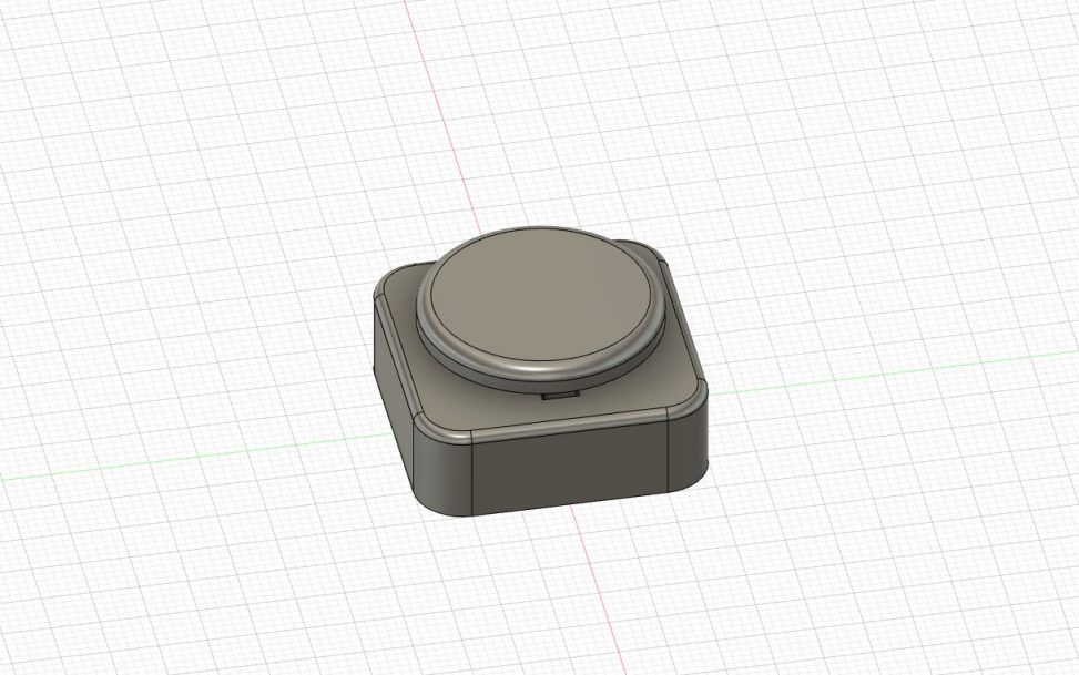
CAD Model of the Button Housing.
Although this prototype was physically the size we wanted, certain dimensions were too small, causing the button to be permanently pressed down, and as the print for the button part failed and it would take several days to a week to print another, I decided to take a different route.

The 3D printed housing was supposed to make an arcade pushbutton larger but proved difficult to design quickly.
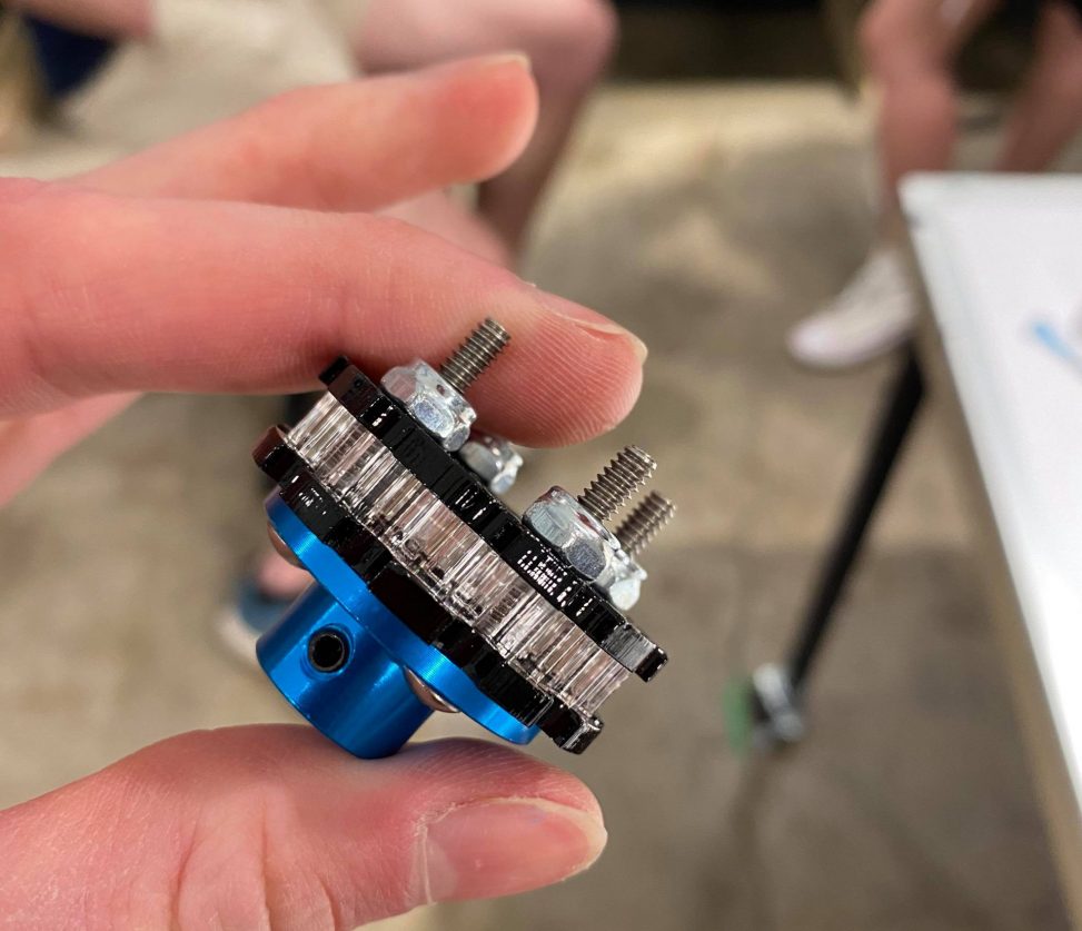
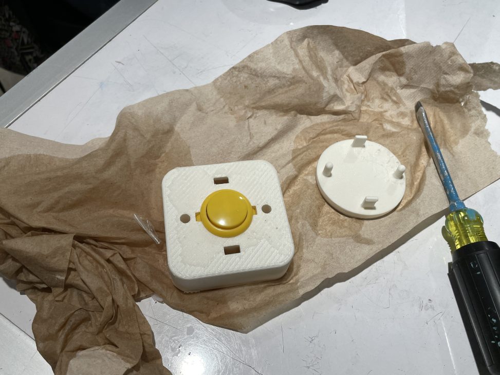
Our client Elaine suggested that we use a manufactured answer button as the basis of our button switch, and “hack” it into a powerless switch that interfaced with the opener through the use of a 3.5mm aux cable. We ended up using this button switch due to its reliability from using a premade, proven-to-work mechanism whilst serving the same function as anything we could 3D print.

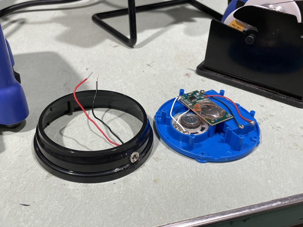
Building the answer button switch.

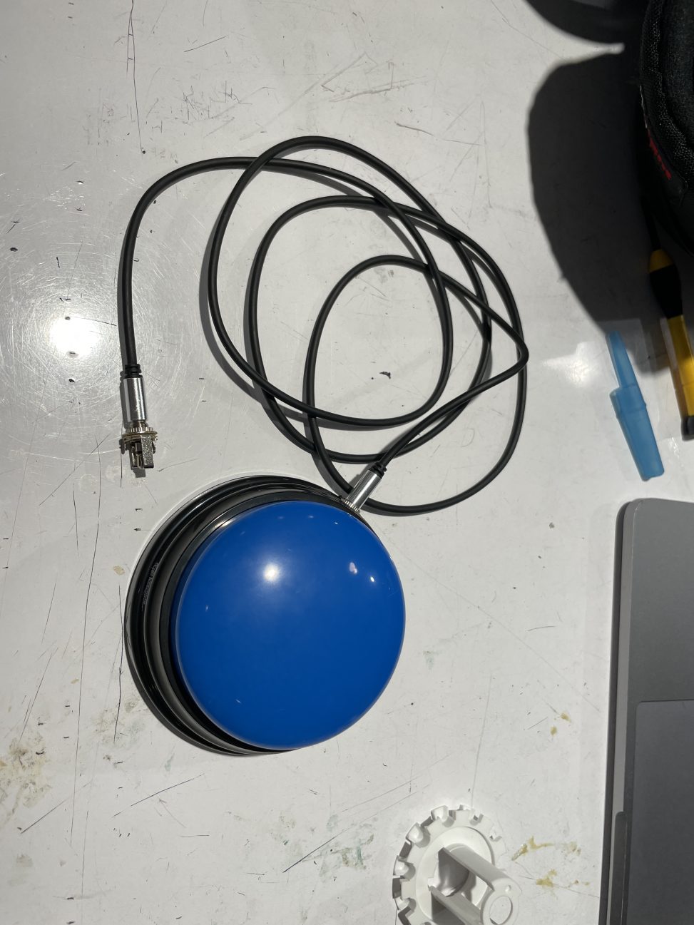
The final working pushbutton switch.
Secondary Tensioner Mechanism
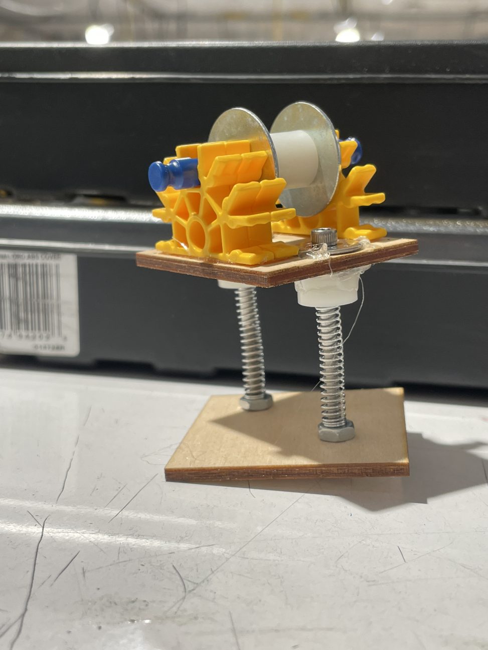
Since we would not have access to Elaine’s blinds due to COVID restrictions, getting exact dimensions of the blinds chain was very difficult, so we built multiple tensioning mechanisms as a safeguard for the opener to work regardless of measurement precision. Our first tensioner was made of K’nex, plywood, and a few hardware bits.

Jud and I redesigned the tensioner later on to make it more compact and interface with the motor sprocket more easily. Here’s a mockup of how the tensioner would attach to Jud’s motor mount box.

Dominique
This prototype was designed to help answer the design questions:
- What mechanism is sufficient for gripping and moving a stiff chain on a set of blinds?
- What might the motor encasing look like?
I created some models of the encasing and the meshing mechanism and iterated over a period of time, slowly focusing more on just the meshing system. The meshing system interfaces with the ball chain on Elaine’s blinds and had to be adjusted to fit those measurements. The encasing took into account the measurements of Elaine’s blinds and how it would attach to he wall.

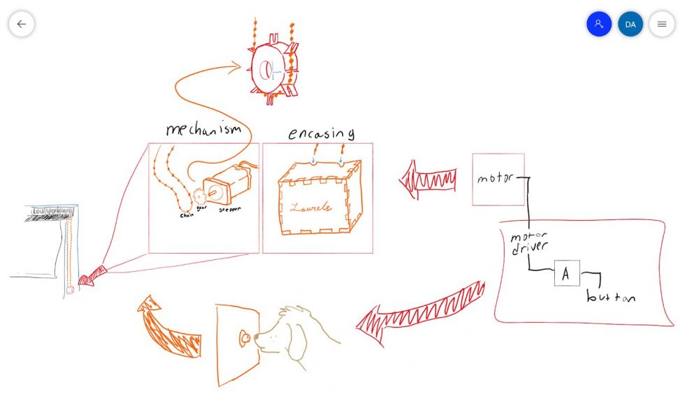
sketch of overall plan for prototype
Meshing Sprocket System
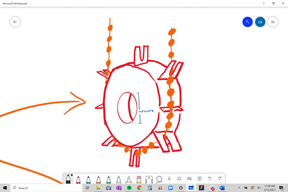
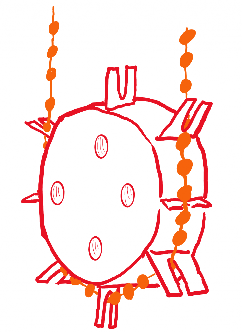
first sketch of meshing gear
↓
Fusion Model of version 1 of meshing system
↓
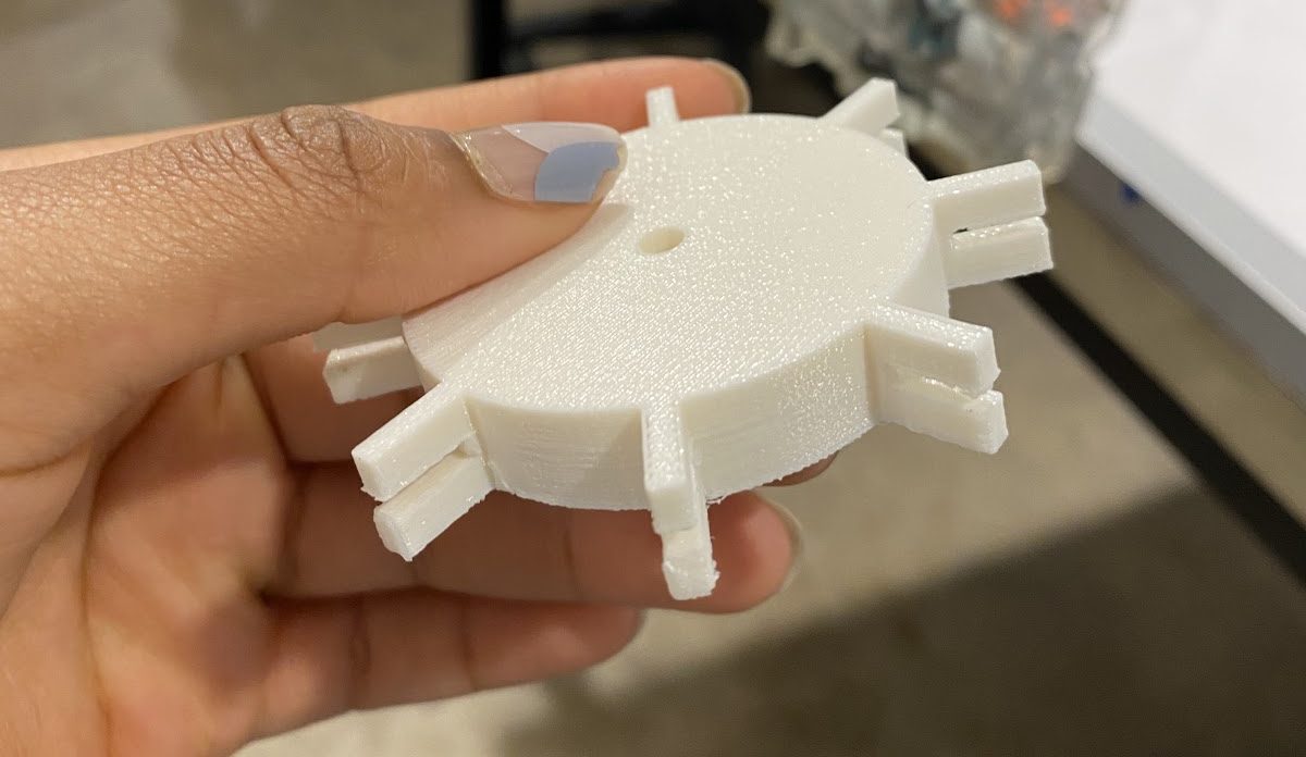
3D printed prototype of meshing system
↓

second sketch of meshing gear, this time with threads because it would mount better with the motor that my teammate found
↓
version 2 3D CAD design. Biggest problem with this is that the threads are too close to edges and measurements in general are off. You can see here that I got rid of the pegs protruding around the gear circumference and designed a sort of alternating plate cut-out. This design was inspired by facory-made blind rollers you might find in IKEA, and is less likely to make the chain get stuck.
↓
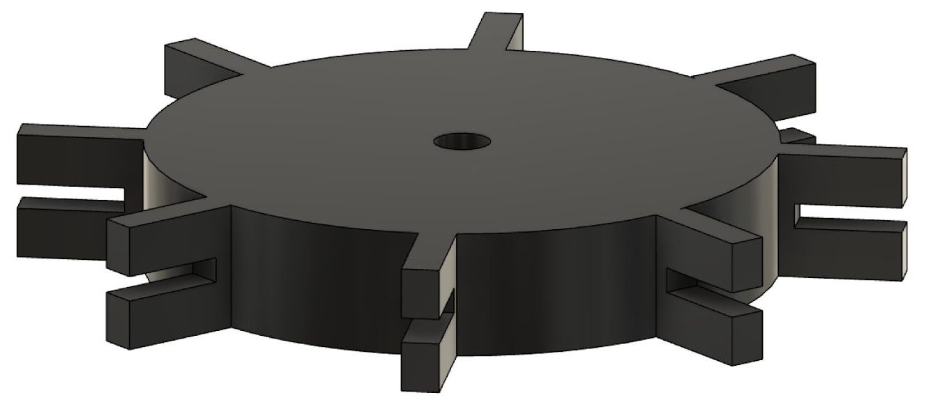
finalized 3D CAD design, fits to specified motor and threads were aken out and replaced with holes for bolts because we were laser cutting, not 3D printing, so threads would only cut the smallest circumference of their spiral, making it impossible to put or bolts in. Also, I realized the diameter of the inner pattern needed to be smaller than the outher plates in order to hold the chain better. Discovered this after looking at the IKEA example again. In this particular gif, I have my design cut open so I could get this inner face for laser cutting purposes, which is why you’re seeing double.
↓
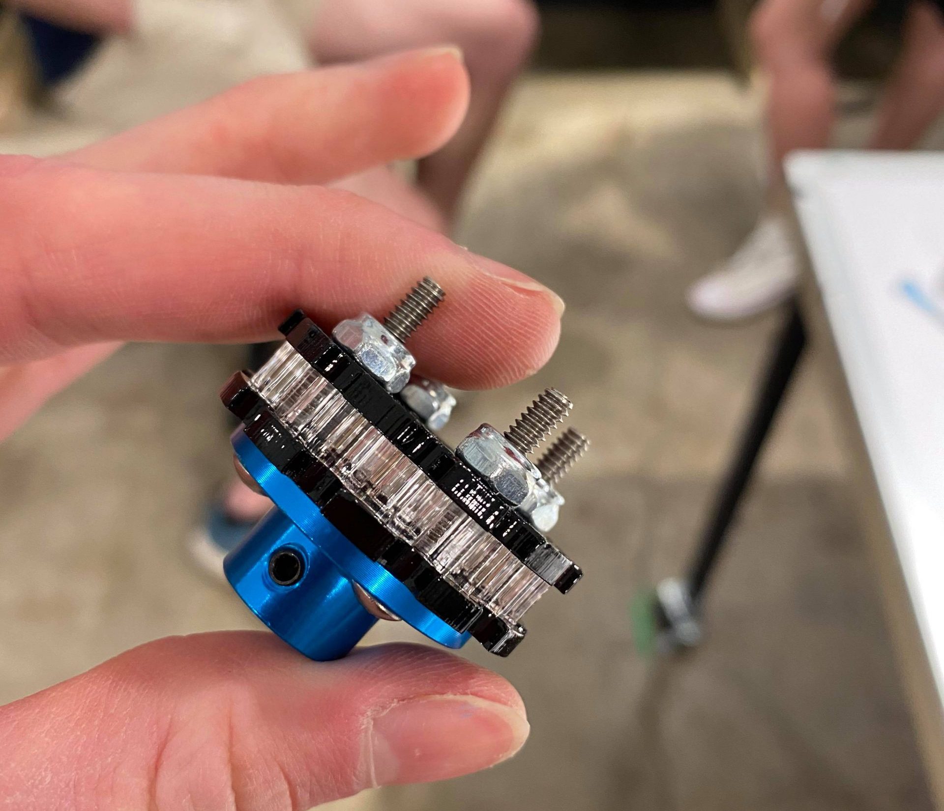
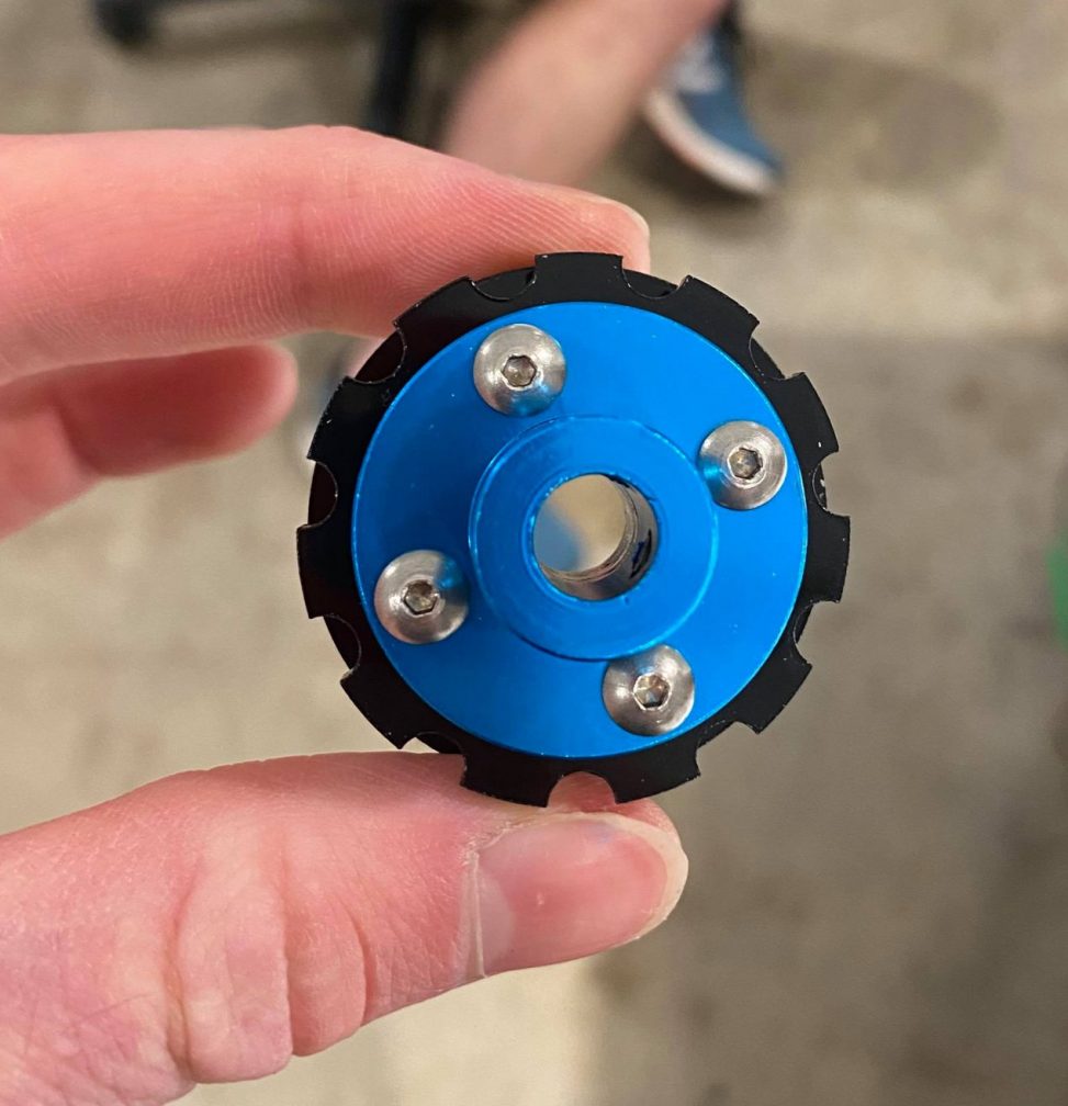
laser-cut meshing system bolted to mounting hub
Encasing
finger-jointed encasing early 3D CAD design to hold the Arduino, protoboard, and motor while also fitting on a window sill. Openings for power and chain. dimensions set up as adjustable parameters. we did not end up pursuing my design much further than this.
To my first prototyping question, I discovered that it would be best to just go off an existing reference since people have invented an automated blinds operator before, so I can just customize it to Elaine’s specific circumstances. It was kind of shooting in the dark because we did not know her exact measurements (distance between balls on chain, diameter of balls, etc.), but we settled on some agreed measurements, 4.5mm diameter ball, a common size. For my second question, even though my design was not used, we were able to use its crit to answer the question of what dimensions would we need to consider for the encasing and how far up on the sill it would need to be, things like that.
The crits did not really focus on my meshing system, however further research on motors and mounts by my teammate, Jud, helped me figure out how to iterate. The pegs did not work, but the final design did. I did not ignore any feedback. During my prototyping process, the biggest surprise was just how many times I had to adjust the size of the threads in the meshing system, due to miscalculations, changes in motor, and so on. And I don’t know why, but changing thread size in Fusion is not as straightforward as I would imagine it might be, and it always took me a long time. I just taught myself Fusion this semester so I was probably also grossly overcomplicating it.
Jud (Motor Behavior and Torque Requirements)
This prototype was built to answer the question of what would the final behavior of the mechanism look like and what components should be used.
This prototype demonstrates the raising and lowering action at the press of the button. As shown in the video below, the curtains will be opened by pressing the button once and then closed by pressing the button again shown by the different rotating directions. As the curtain is raised, the distance that travelled by the curtain is measured ensuring the curtain is completely raised or lowered before stopping.
Overall

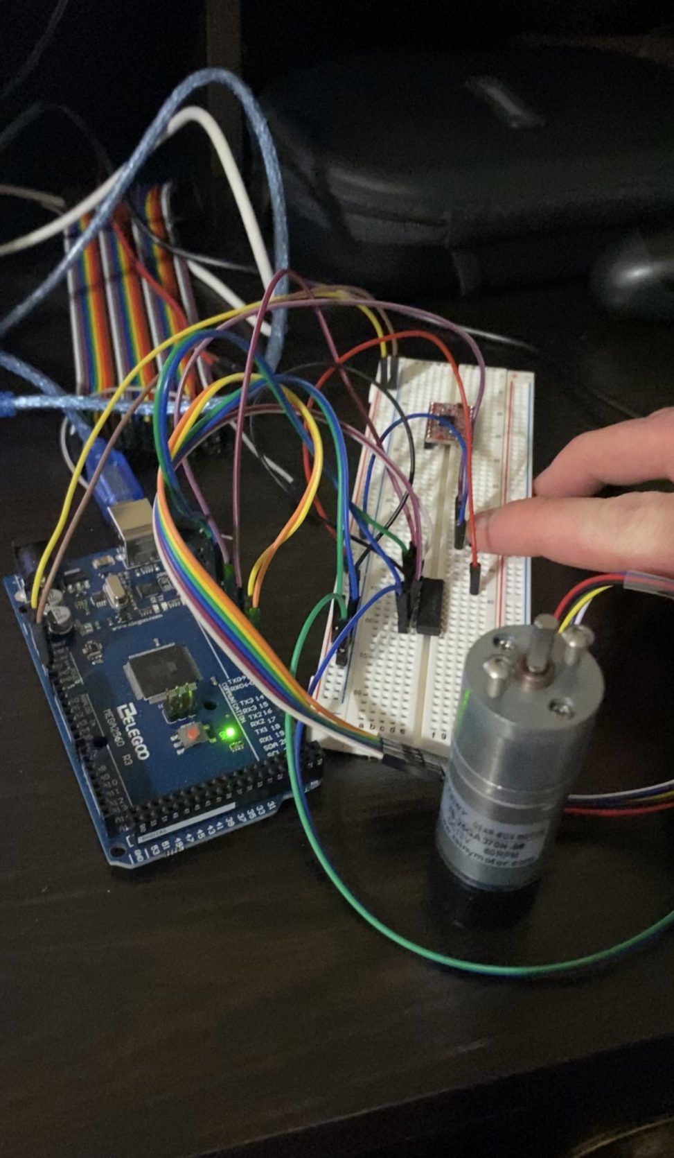
Overall image of general movement prototype. Shown is the motor attached to the H-bridge motor driver for speed control as well as the wiring to the Arduino Mega.
Motor Driver Wiring
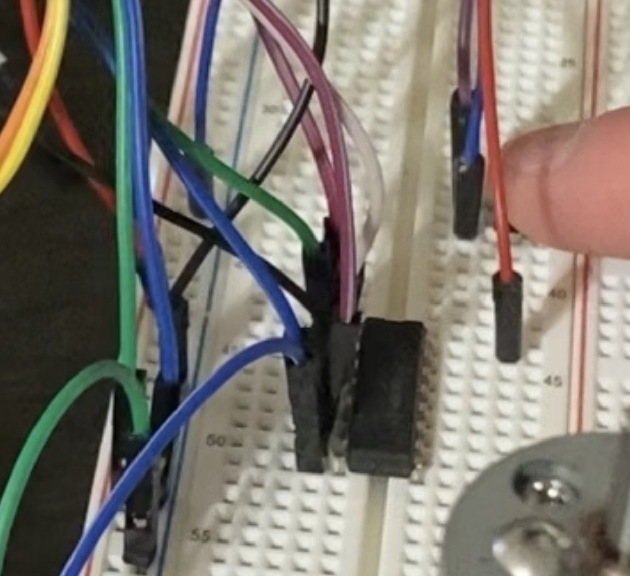
Close up of the wiring for the prototype. Here, the L293D H-Bridge is being used to drive the attached motor with a 12V power supply.
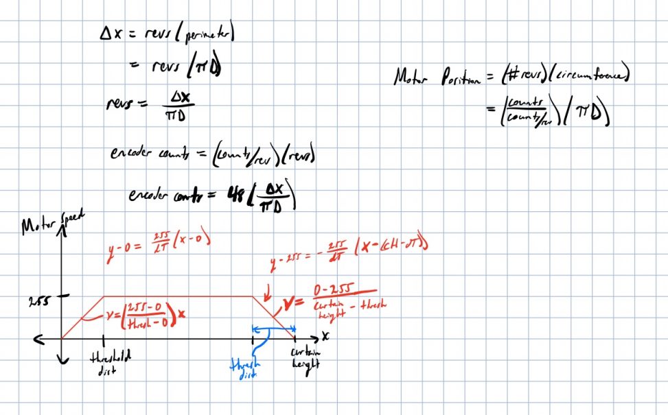
Speed Control Calculations
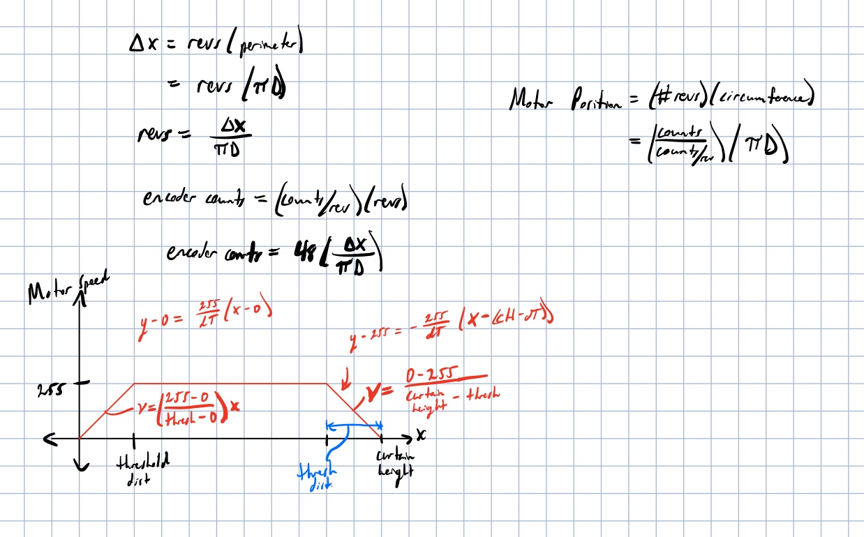
Screenshot of the calculations controlling the speed of the motor. As shown, the speed of the motor slowly ramps up until the max speed is attained and then slowly ramp downs at a certain threshold distance away from the final distance.
Video
Improvements
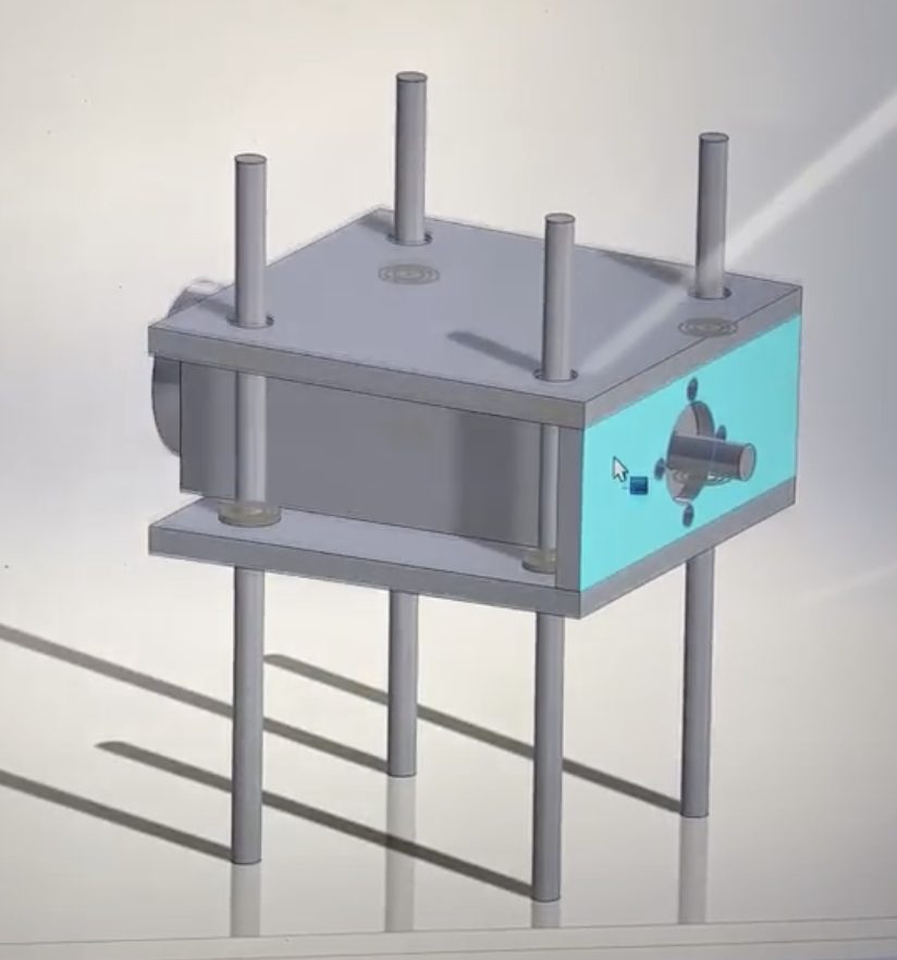
3D model of the motor mount used for the final design. As shown, the motor mount has more adjustability to allow for more accurate positioning of the motor with respect to the ball chain.

Image of the power supply connected to the outer housing. As suggested by Elaine, this style of power adapter was used because of its ease of use. The barrel jack style adapters allow for easier plugging and unplugging as well as more customization in the future with regards to cable lengths.
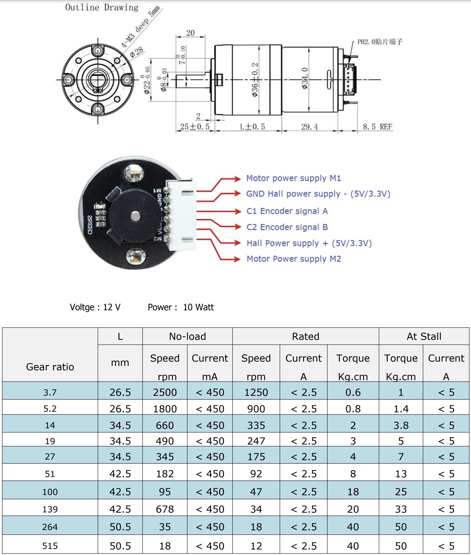
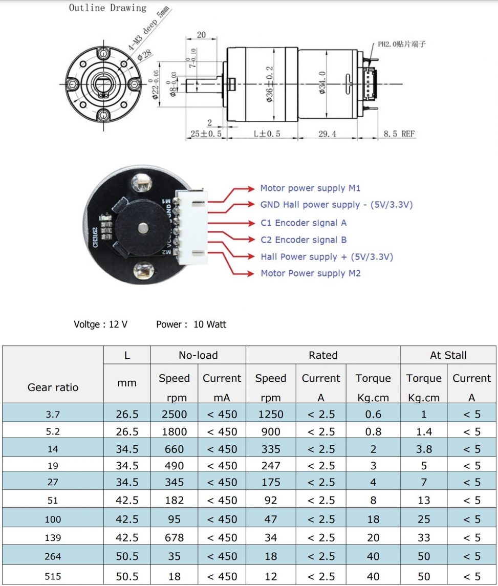
Screenshot of the specification sheet for the final motor. As shown, the motor has more than enough torque to raise the curtains ensuring the reliability of the device.
After this initial prototyping, we found that the best motion for the motor would be a slow starting and stopping motion in order to reduce the damage to the motor. In addition, this type of motion would result in a smoother looking operation thus improving the overall appearance of the device. In addition, from the calculations for the torque required to lift curtains similar to Elaine’s, we discovered that the motor would need to be able to lift around 13lb. With this number and the dimensions of our final gear mechanism, the motor we needed to order for the final device needed to be capable of outputting around 20kg*cm of torque. This amount of torque was higher than the minimum required torque in order to ensure that our device would work reliably.
After the prototyping critique, we received lots of feedback on different ways to improve the device including different button pressing actions that would allow the curtains to stop midway through if the button was pressed again. While this type of behavior is something that would’ve been useful to have, we decided to leave this feature out of the final device because we ran out of time to incorporate it. In addition, we also received lots of feedback on ways we could make the device easier to use by reducing the number of electrical connections necessary to power the device. Since the final device needed a 12V power supply for the motor and a 5V power supply for the rest of the electronics, we decided to incorporate a 5V regulator into the final device that would be able to take the 12V from the motor power supply and convert it to 5V for the rest of the circuitry.
Process
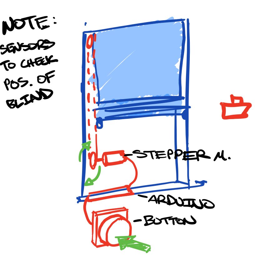
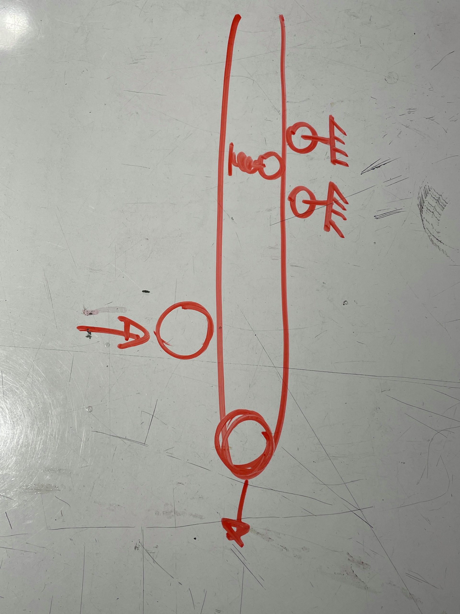
preliminary sketch of project for scoping
We started out with three ideas after our first interview with Elaine, but of course, this is the one we chose, sketch courtesy of Eric.
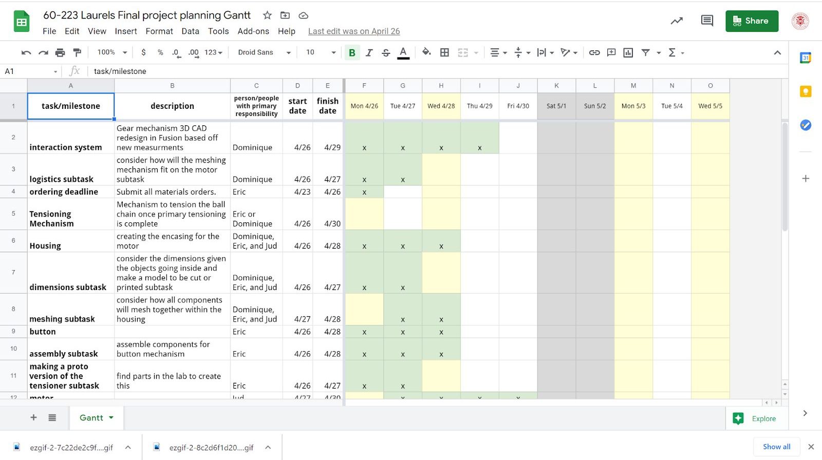
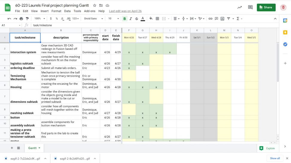
Our Gantt chart
We tried to organize or plan according to our abilities and also with the idea in mind that our building would be delayed until our motor came. We figured that it would show up the week we were planning it all out, but that was not the case and we had to adjust our scheduling to fit this delay.

Amazon sprocket example screenshot
The design that inspired Dominique’s CAD designs. These measurements are also what we originally went with, but we adjusted the space provided for in-between the balls a bit.
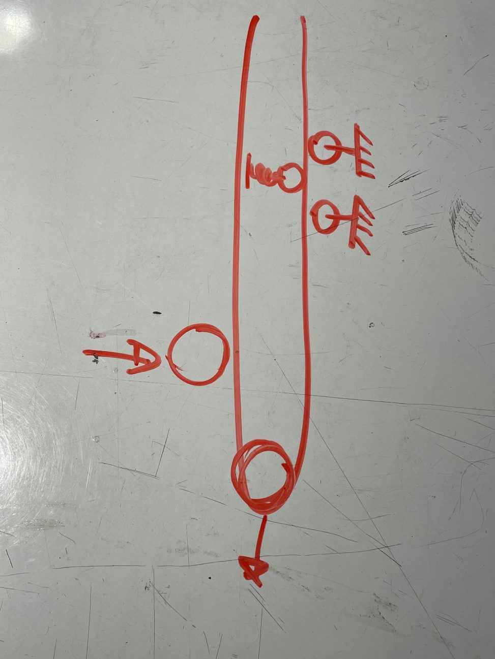
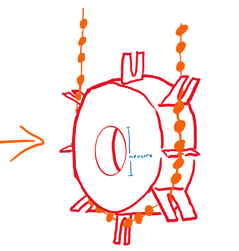
tensioning sketch
We also had to take time to consider what tensioing on the chain and motor might look like so that the movement can be smooth. This drawing by Jud is for the secondary tensioner, and was later prototyped by Eric.
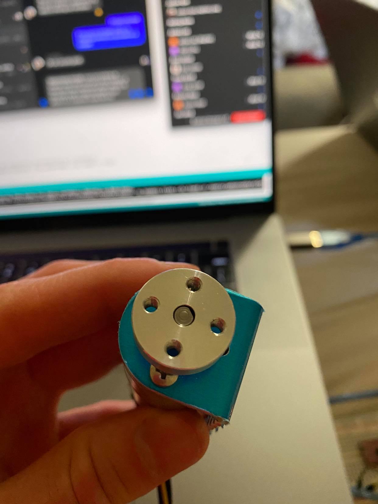
the motor that changed our sprocket design
Jud found this motor, which he determined had a better mounting system for our purposes, and so Dominique redesigned the model of the sprocket with this in mind, although we did not end up going with threads.

unfortunate email
Not long after, we did get word that our motor delivery would be delayed until after the final crit, and so we had to improvise with a different motor from IDeATe Lending. Everything worked as planned, but it would be good to switch the motor out for Elaine.
Conclusions and lessons learned
Crit Feedback & Response
- “It was difficult to understand exactly how it would interface with the blinds from the presentation just cause there was no chain to demo with.”
- This is a fair point, it would definitely be clearer to have had a chain on there. The hard part is getting the chain for a set of blinds in a remote setting. I think at least what we could have done for clarity sake would be to use a rope or string just as a demonstration of how everything would be placed including how the sprocket interfaces with that rope. This way people would not just be looking at a spinning motor arm. In addition, having the actual motor would’ve been very useful in conveying the actual functionality of the device which was unfortunately not possible for the critique.
- “Having all four rods be threaded seems like you’re asking for trouble? Why not one threaded rod and three smooth ones? This seems like it could get locked up by accident really easily.”
- This is a very good point, however, the four threaded rods used in the four corners of the motor mount were only used as aligning rods. In our original design, springs were supposed to help keep the motor mount in place on all four rods, and since we didn’t have enough springs to place the motor mount high enough, we needed a way to raise the first set of springs up slightly. In order to do this, threaded rods with nuts attached were supposed to be used, however, this mechanism was eventually replaced with nylon couplers. In the future, it would probably be better to use smooth rods for all four rods to reduce the risk of the motor mount catching during tensioning since the threads ended up not being utilized in the final design.
- “The 3D-printed sprocket gear could use some fillets at the base of the teeth? They look like they are at risk of snapping off. Forces will build up otherwise.”
- The final sprocket design is actually quite thick, at least one centimeter and is made out of acrylic and is reinforced by a metal mounting hub. When comparing that build to the thinner IKEA version which was actually just plastic, our sprocket is actually much stronger, so assuming that the factory version is still sturdy enough to interface with a chain, we believe our build would be more than fine as well. Also, the direction of the force will never push directly on the protruding alternating plates. Even still, this is a great note for our first version of the sprocket.
- “Have you considered the fire safety of your sprocket? The constant rubbing might make it catch fire easily.”
- That’s also a good note, we had not actually considered this. However, I don’t think acrylic catches fire…it seems more like it would melt. But I’m not sure about that and it would be good to look into for safety purposes.
Working remotely
It was challenging to communicate in a timely manner. Elaine herself was going through a lot and was telling us about how Oak was quite sick and in the ER. She was also very busy in general and was not able to get back to us very often making it hard to have a smooth design process. On the other hand, working remotely made it super easy to hop on a call and get specifics about measurements and things, rather than having to go all the way to he home to see what her set up looked like.
If there is one thing we might have done differently, I would say that it’s get our laser cutting done much earlier. It was not fun rushing to laser cut our sprocket before the lab closed. In addition, it would’ve been very useful to assess the components necessary for the final build a lot sooner so the final product on critique day would be fully finished.
Working with a disabled client
Working with Elaine was such a pleasure. She has limited mobility but is otherwise very independent and has a lot of great ideas. It did help that she is an expert in robotics and engineering topics and had a lot of great suggestions for us on how to simplify our project. One major takeaway we learned is that it’s super important to consider how processes can be made easier for different stakeholders, so in this case not only Elaine, but her dog. Assistive devices do not have to be operated by humans all the time. It was also a very rewarding experience thinking about solutions to problems in different was than we would otherwise. This new way of thinking led to many different new and creative ideas that we will be able to take forward into future projects and life in general.
Concluding thoughts
Next time, it would be great to have a backup plan for parts arriving late. Perhaps we could have designed two sprockets one that fits the motor we have now, and one that fits the one still coming. Overall, this was a great learning experience and a fun project, and we hope that Elaine can get some use out of her new system!
Technical information
Block Diagram
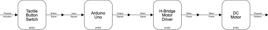
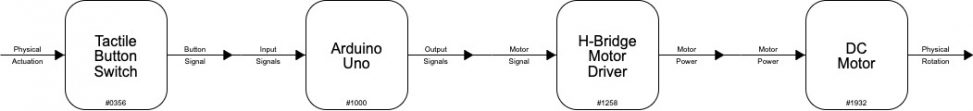
Functional block diagram of the dog activated blinds opener.
Electrical Schematic

Electrical schematic of the dog activated blinds operator.
Code submission
/*
  60-223, Final Project
  Jud Kyle (jkyle), Eric Zhao (ezhao), Dominique Aruede (daruede)
  time spent: 24 hours

  Collaboration and sources:
  - Encoder_Interrupts functions copied from 24-354 Gadgetry lab code

  Description:
  - This sketch drives an automatic blinds opener. When the button is pressed,
    the blinds will begin rotating in one direction for the desired length until
    entered as the curtainHeight in mm. When the motor starts rotating and stops
    rotating, the speed is slowly increased and decreased to reduce the negative
    impacts on the motor. Each time the button is pressed, the motor will not stop
    rotating until the full distance has been travelled. The direction the motor spins
    changes upon each button press to go up if it had previously gone down and vice
    versa.

  Pin mapping:
  Arduino pin | type   | description
  ------------|--------|-------------
  2             input    Button input pin
  3             input    Encoder A input pin
  4             input    Encoder B input pin
  8             output   Motor direction pin 1
  9             output   Motor direction pin 2
  10            output   Motor PWM pin for speed
*/

// Pin Variables
const int BUTTONPIN = 4;
const int encoderPinA = 2, encoderPinB = 3;
const int motorPin1 = 9, motorPin2 = 8, motorPWM = 10;

int encoderCount = 12 * 98; //12 encoder counts per revolution with 1:98 gear ratio

bool motorSpinning = false;

// Motor distance measuring variables
volatile long currentEncoder_pos_f = 0, prevEncoder_pos = 0, revs = 0;
float curtainHeight = 0.5, motor_D = 0.02, thresholdDist = 0.0255; //mm
float motorSpeed = 0, motor_pos_f = 0;

// initialize the stepper library on pins 4 through 7:

// determines which direction the motorspins upon button-press
String motorDirection = "CW";

void setup() {
  pinMode(BUTTONPIN, INPUT_PULLUP);

  pinMode(motorPin1, OUTPUT); pinMode(motorPin2, OUTPUT);
  pinMode(motorPWM, OUTPUT);

  // initialize the serial port:
  Serial.begin(9600);

  //Initialize interrupts
  attachInterrupt(0, encoderA, CHANGE); //Pin 20
  attachInterrupt(1, encoderB, CHANGE); //Pin 21

}

void loop() {
  int buttonVal = digitalRead(BUTTONPIN); //Read pressed state of the button

  float motor_pos_f = (((float) currentEncoder_pos_f) / (4 * ((float) encoderCount))) * 3.14159 * motor_D; // Convert encoder counts to distance travelled
  if (motor_pos_f < 0) { // Ensure distance is always positive
    motor_pos_f = motor_pos_f*(-1.0);
  }

  Serial.print("Motor Position: ");
  Serial.print(motor_pos_f, 7);

  //Update spinning condition when button is pressed
  if (buttonVal == LOW && motorSpinning == false) {
    motorSpinning = true;
    currentEncoder_pos_f = 0;
    //Update motor direction
    if (motorDirection == "CCW") { //Spin motor CW
      digitalWrite(motorPin1, HIGH); //Spin CW
      digitalWrite(motorPin2, LOW); //Spin CW
      motorDirection = "CW";
    } else if (motorDirection == "CW") {    //Spin motor CCW
      digitalWrite(motorPin1, LOW); //Spin CCW
      digitalWrite(motorPin2, HIGH); //Spin CCW
      motorDirection = "CCW";
    }
  }

  Serial.print("\t Toggle: ");
  Serial.print(motorDirection);

  //Spin motor in corresponding direction
  if (motorSpinning == true) {
    if (motorSpeed < 50) { //Minimum PWM signal for starting motor
      motorSpeed = 50;
    }
    else if (motor_pos_f > curtainHeight) { //Stop motor when full distance is reached
      motorSpinning = false;
      motorSpeed = 0;
    }
    else if (motor_pos_f < thresholdDist) { //Ramp up speed at start
      motorSpeed = (255 / thresholdDist) * motor_pos_f;
    }
    else if (motor_pos_f > curtainHeight - thresholdDist) {
      motorSpeed = 255 - (255 / thresholdDist) * (motor_pos_f - (curtainHeight - thresholdDist)); //Ramp down speed at end
    }
    else {
      motorSpeed = 255;
    }
  }
  analogWrite(motorPWM, (int) motorSpeed); //Set motor speed equal to integer value of motor speed

  Serial.print("\t Motor Speed: ");
  Serial.println((int) motorSpeed);


  //Track position of motor using encoder (count number of revolutions and multiply by a distance)
  //Update speed according to position (If within a certain distance, slow speed down, else speed is HIGH)
}

void encoderA(){

  // look for a low-to-high on channel A
  if (digitalRead(encoderPinA) == HIGH) {
    // check channel B to see which way encoder is turning
    if (digitalRead(encoderPinB) == LOW) {

        currentEncoder_pos_f = currentEncoder_pos_f + 1;         // CW
    }
    else {
        currentEncoder_pos_f = currentEncoder_pos_f - 1;        // CCW
    }
  }
  else   // must be a high-to-low edge on channel A
  {
    // check channel B to see which way encoder is turning
    if (digitalRead(encoderPinB) == HIGH) {

        currentEncoder_pos_f = currentEncoder_pos_f + 1;          // CW
    }
    else {
        currentEncoder_pos_f = currentEncoder_pos_f - 1;          // CCW
    }
  }
}

void encoderB(){

  // look for a low-to-high on channel B
  if (digitalRead(encoderPinB) == HIGH) {
   // check channel A to see which way encoder is turning
    if (digitalRead(encoderPinA) == HIGH) {

        currentEncoder_pos_f = currentEncoder_pos_f + 1;         // CW
    }
    else {
        currentEncoder_pos_f = currentEncoder_pos_f - 1;         // CCW
    }
  }
  // Look for a high-to-low on channel B
  else {
    // check channel B to see which way encoder is turning
    if (digitalRead(encoderPinA) == LOW) {
        currentEncoder_pos_f = currentEncoder_pos_f + 1;          // CW
    }
    else {
        currentEncoder_pos_f = currentEncoder_pos_f - 1;         // CCW
    }
  }
}