Introduction:
For the final project, we met with our client Haleigh Sommers, who lives life in a wheelchair and must place her common devices (phone, Kindle, laptop) on an attached tray in front of her. However, she often has trouble craning her neck down to interact with devices, and also feels uncomfortable using a small detachable stool that her mother can place for her; it is not very adjustable. Haleigh also emphasized that she would like to be able to adjust the position of her device herself, rather than having her mother constantly make adjustments.
In order to gauge the scope of this problem, we engaged in a comprehensive Zoom chat with Haleigh, not only getting a sense of her daily challenges but also getting to know her as a person. The three of us brainstormed solutions over a whiteboard while simultaneously receiving feedback from Haleigh, until we decided upon the idea for our device: an adjustable viewing platform. Through this interview, we built a clear picture of our client and the types of solutions she prefers.
What we built:
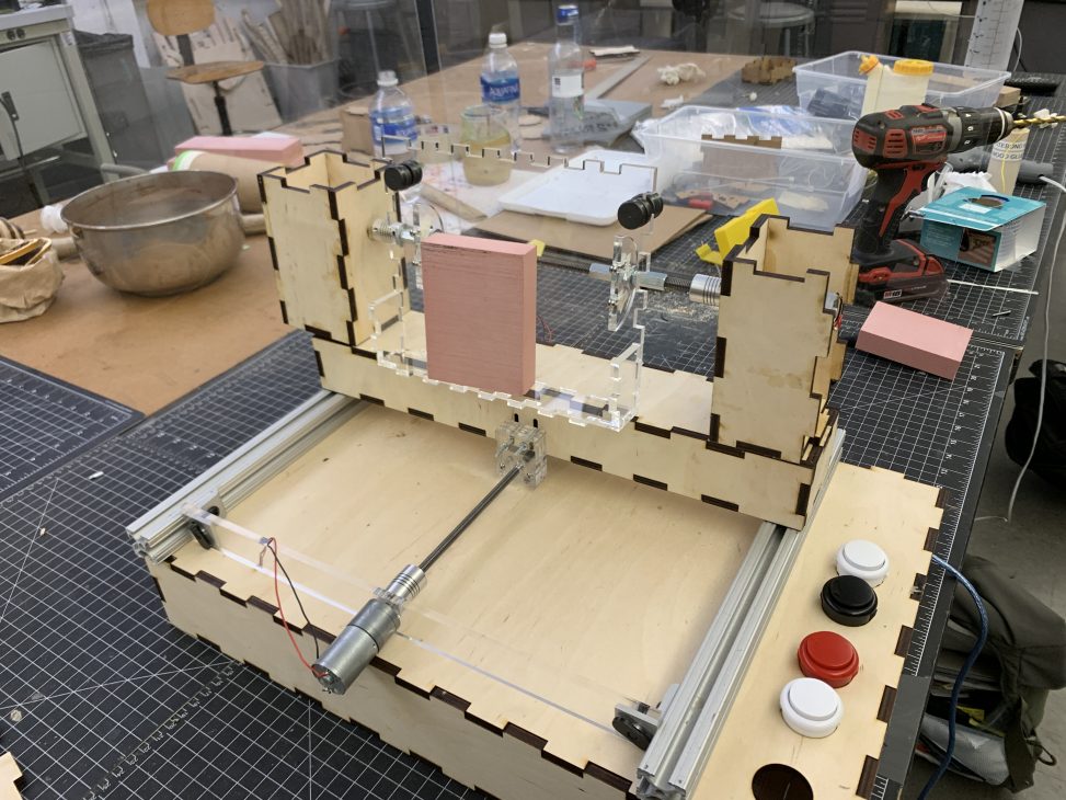
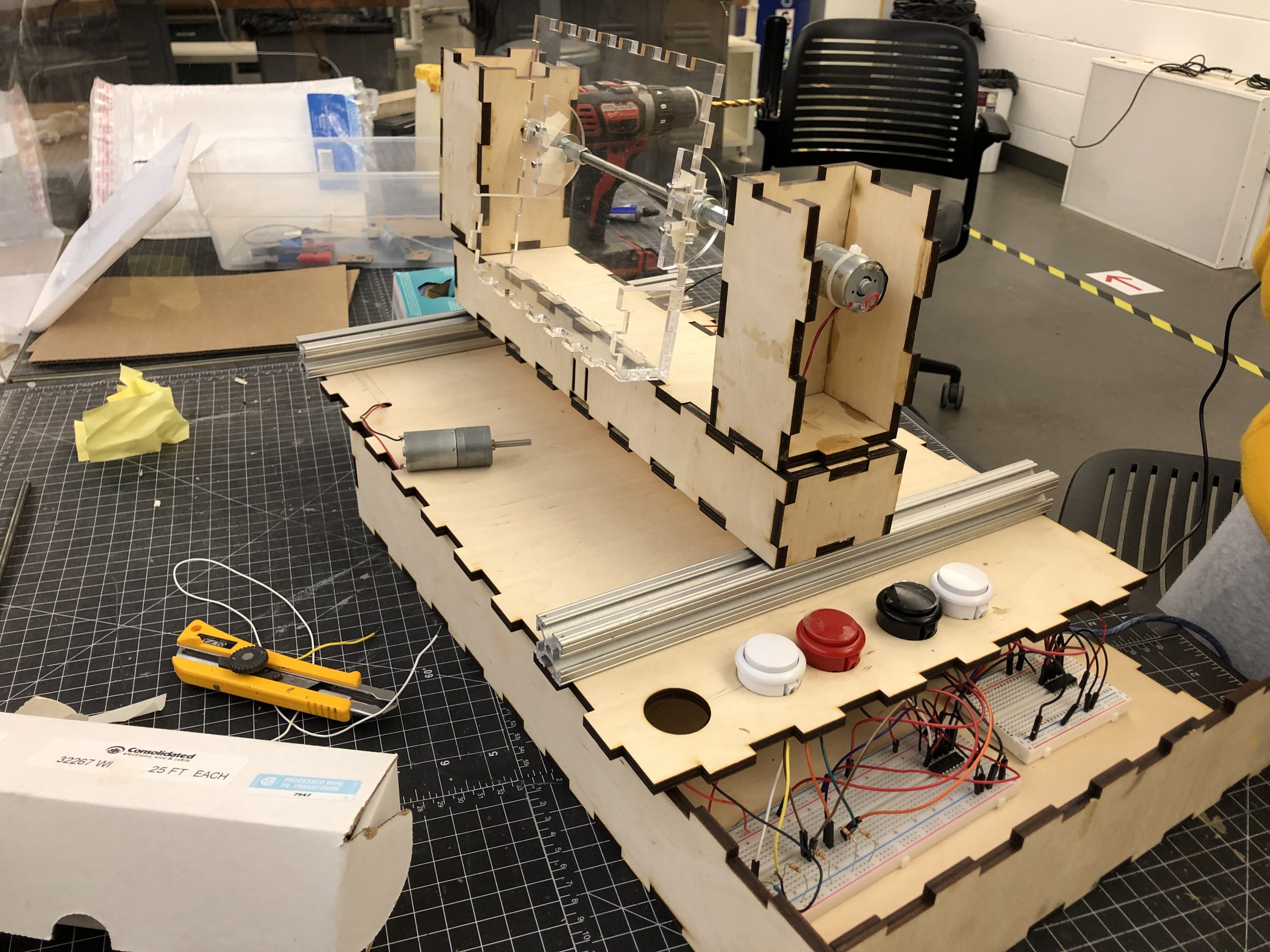
We built a contraption that can adjust the distance and orientation of Haleigh’s chosen device. Specifically, the contraption adjusts the distance from Haleigh through a sliding mechanism, moving back and forth along two rails on either side of her desk. The orientation of the device can also be adjusted. Both the sliding and tilting mechanisms are controlled through pressing and holding one of four total buttons (two for sliding, two for tilting).
Featured Image:

In Action:
Sliding mechanism:
Tilting mechanism:
Detail Images (4):
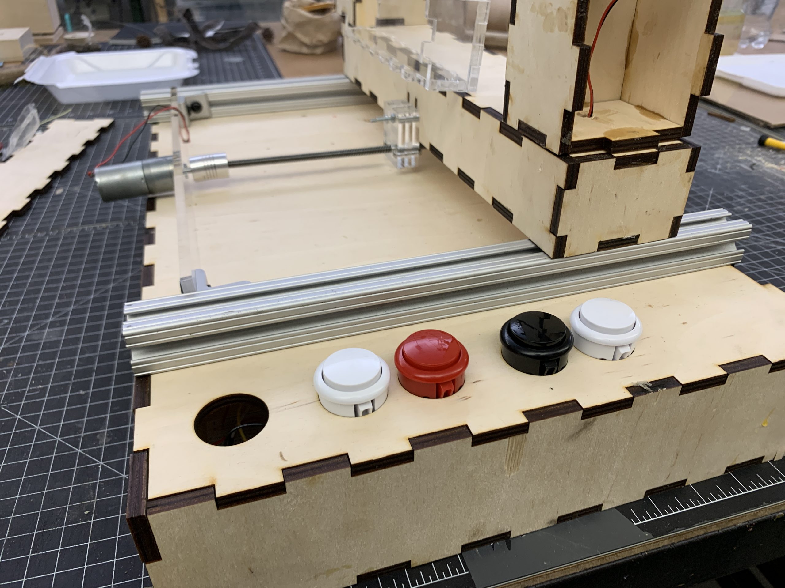
Button view: Red/White = Sliding, Black/White = Tilting
Internal view of circuitry
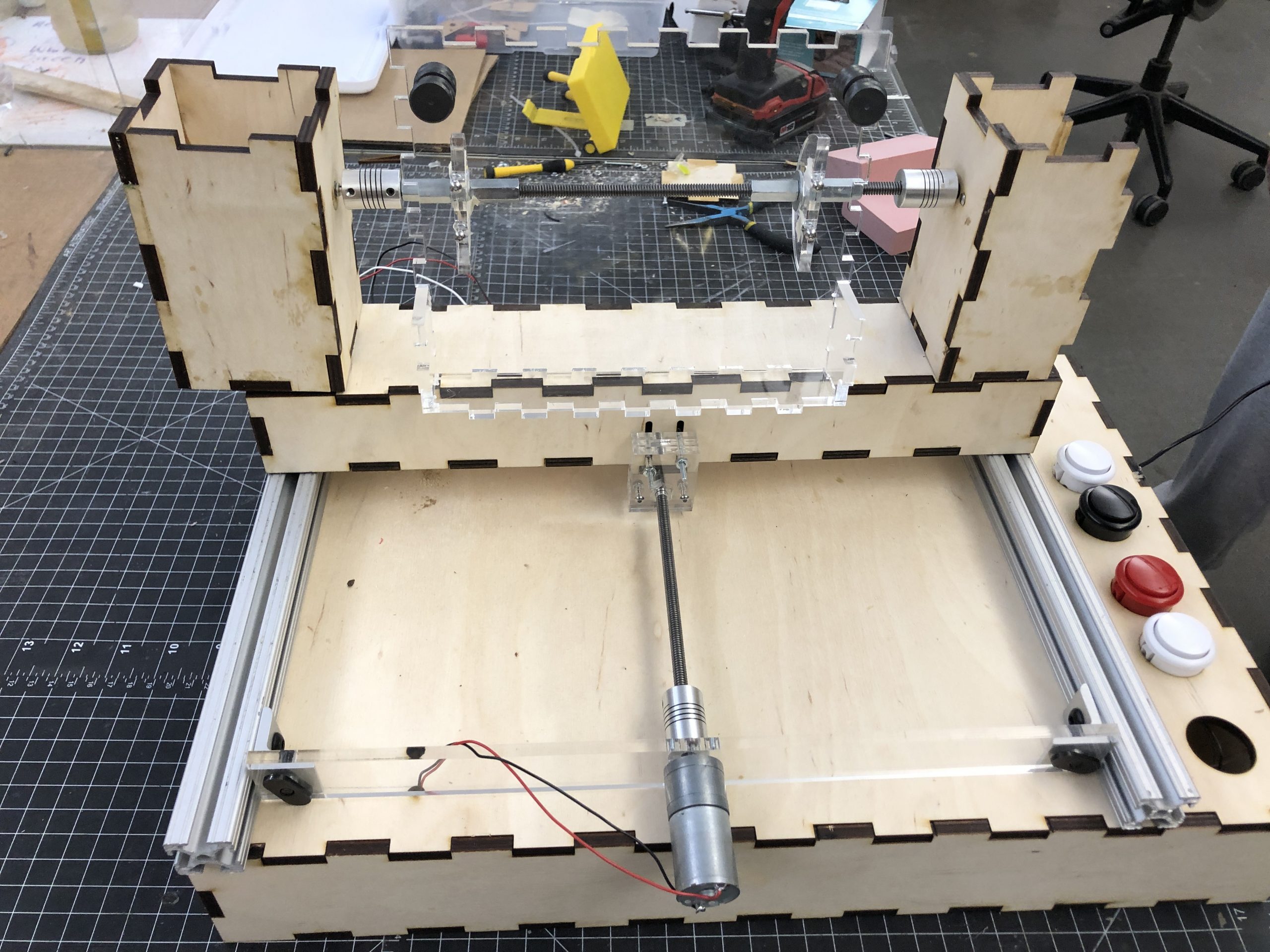
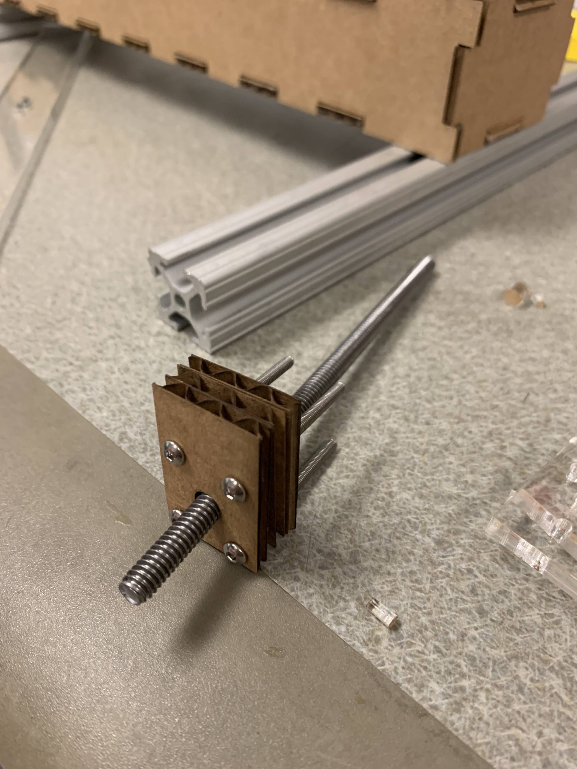
Top view of sliding mechanism: rotating screw
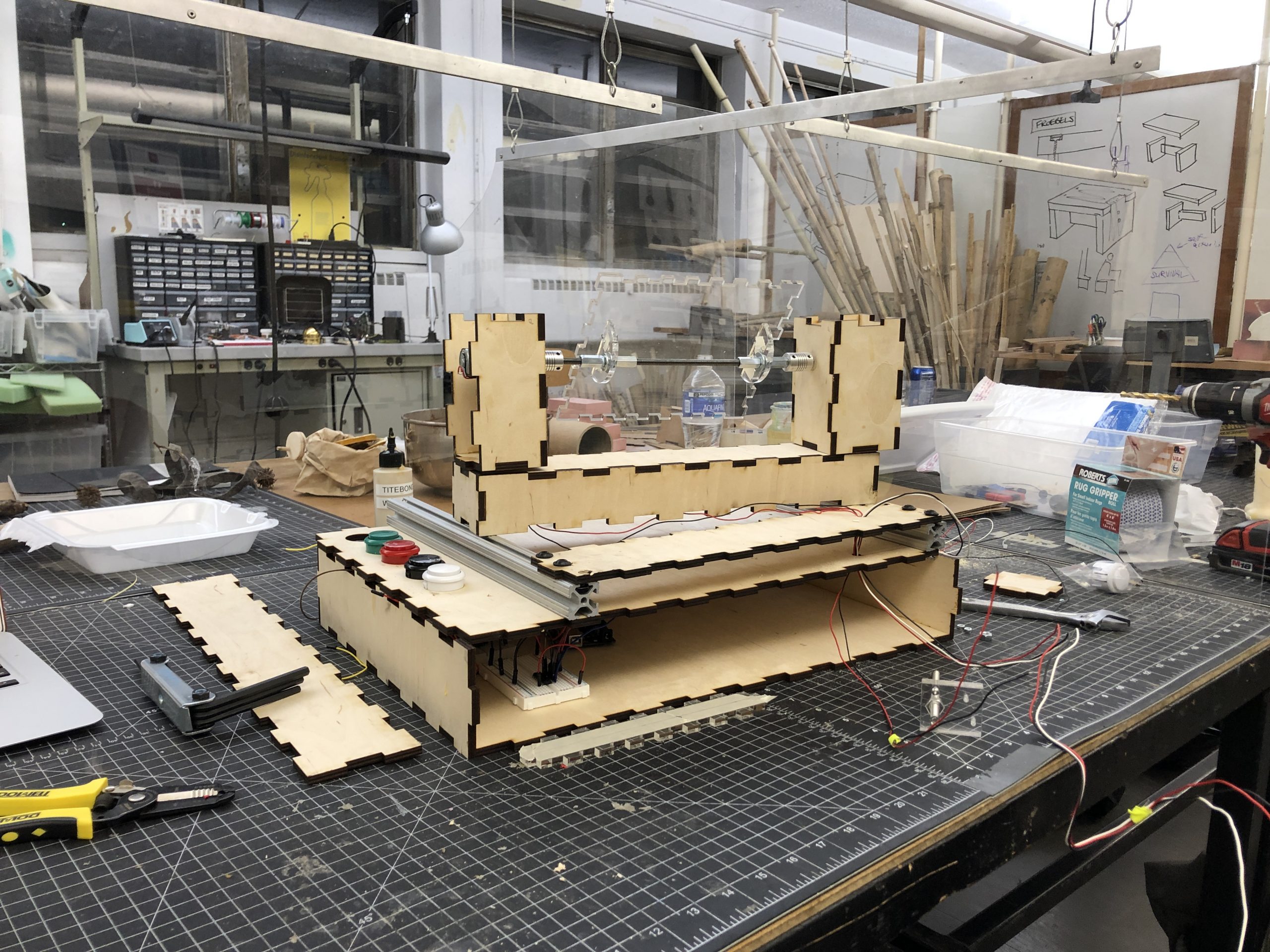
Comprehensive view of circuitry connecting to hardware
Narrative Sketch:
Haleigh is a busy student, and she needs to get some homework done before the deadline tomorrow. However, she finds it tough to see and interact with the small text on her phone and computer screen. She pressed a button to bring the computer holder towards her; now she can read the instructions of the homework assignment. After she submits the assignment, she hears a text notification on her phone, but it’s hard to read it without craning her neck. So she presses another button, which angles the surface, bringing the phone to a comfortable position so she can type out a response.
How we got here:
Prototypes:
Vishnu
Rotating mechanism
Questions we wanted answered:
- How much force can the device handle?
- What pieces would fit together to produce the rotating axle?
- How technically complicated would controlling degree of rotation be?
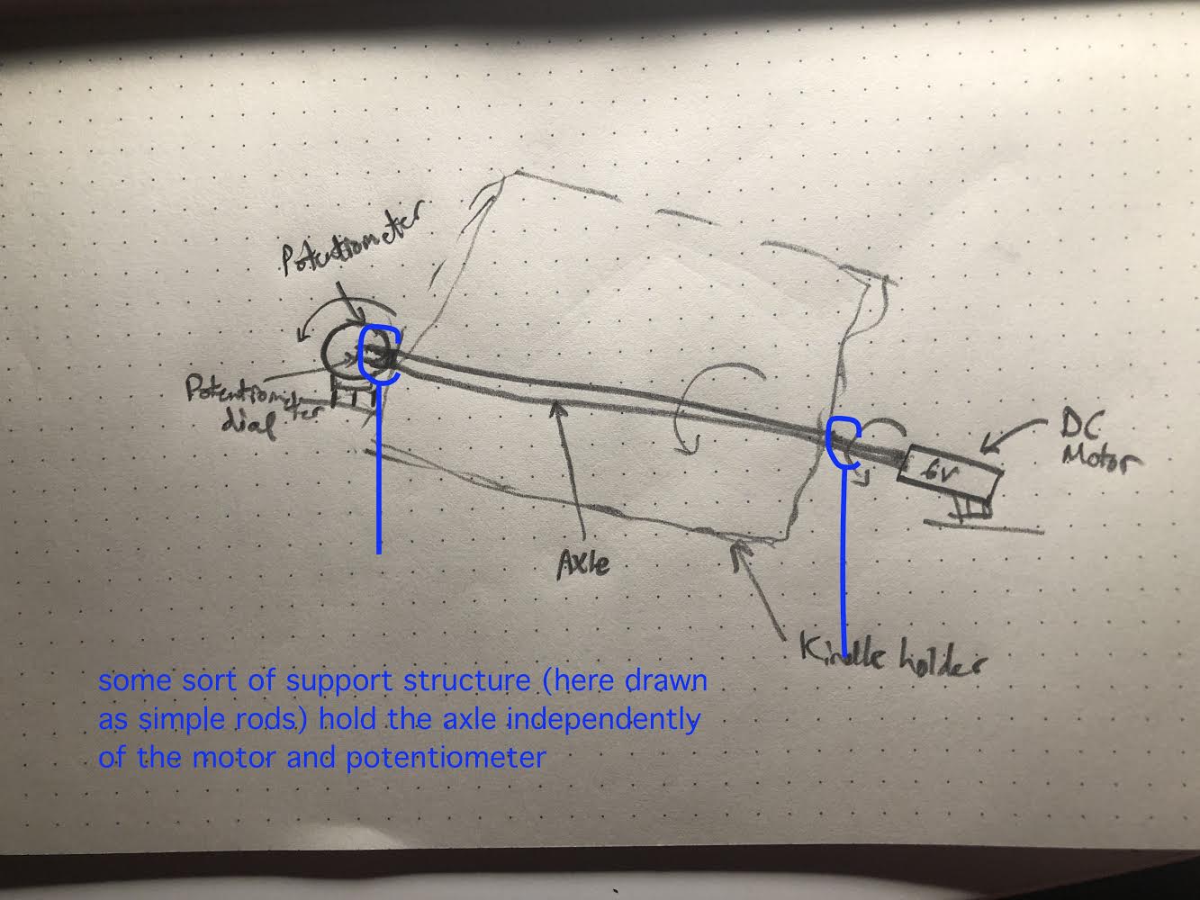
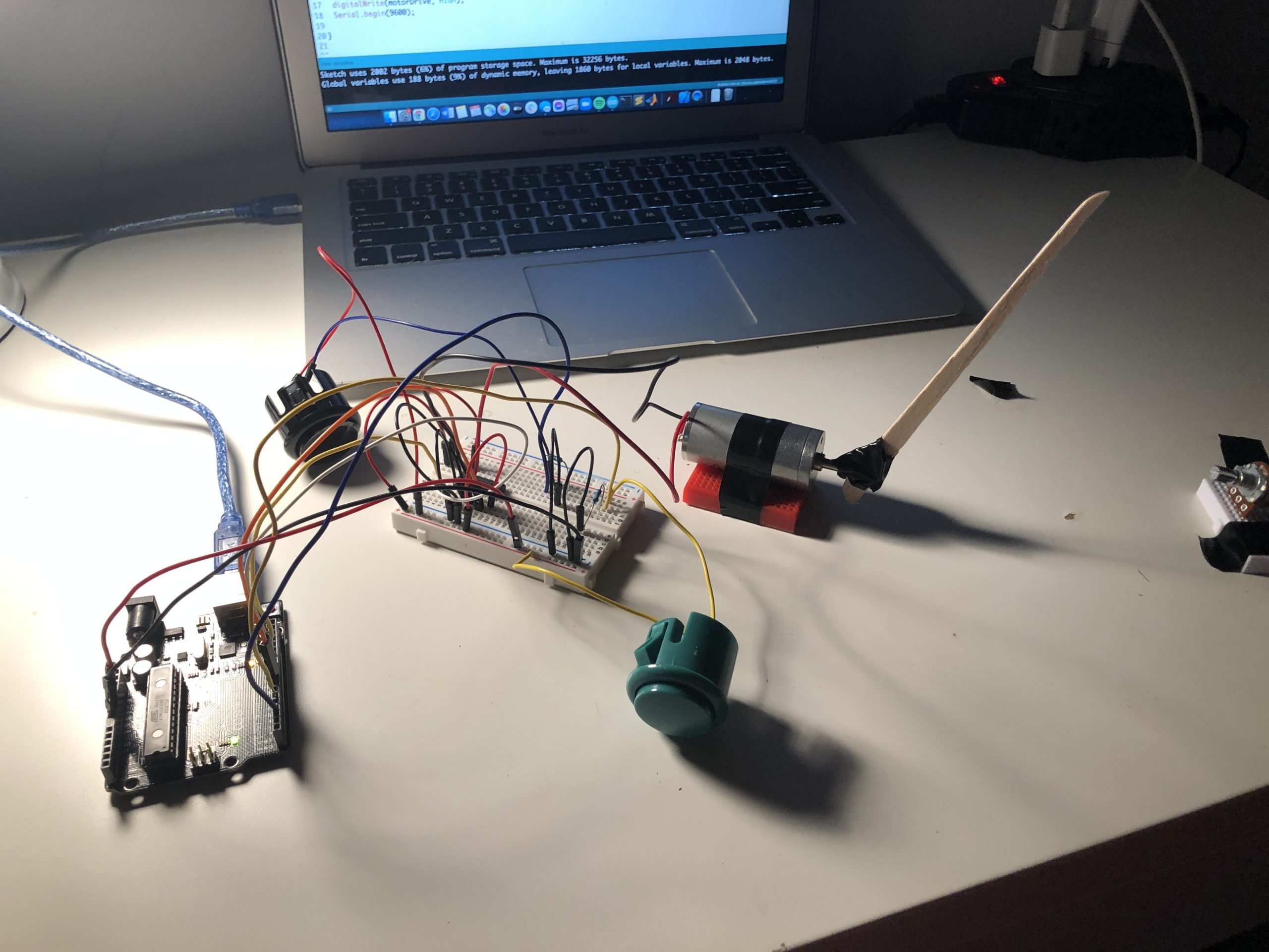
The first prototype was to test the rotating section of the device. Essentially, Haleigh can press one of two buttons, and the surface will rotate clockwise or counterclockwise.
To achieve this, we connected a DC motor to a potentiometer. The potentiometer would read the current angle, and also prevent the motor from turning past a certain angle (range: 0 to 70º). The platform is connected on a rod between the motor and the potentiometer.
Close-up of rotator (note placement of DC motor and potentiometer)
Scale Image of rotational portion
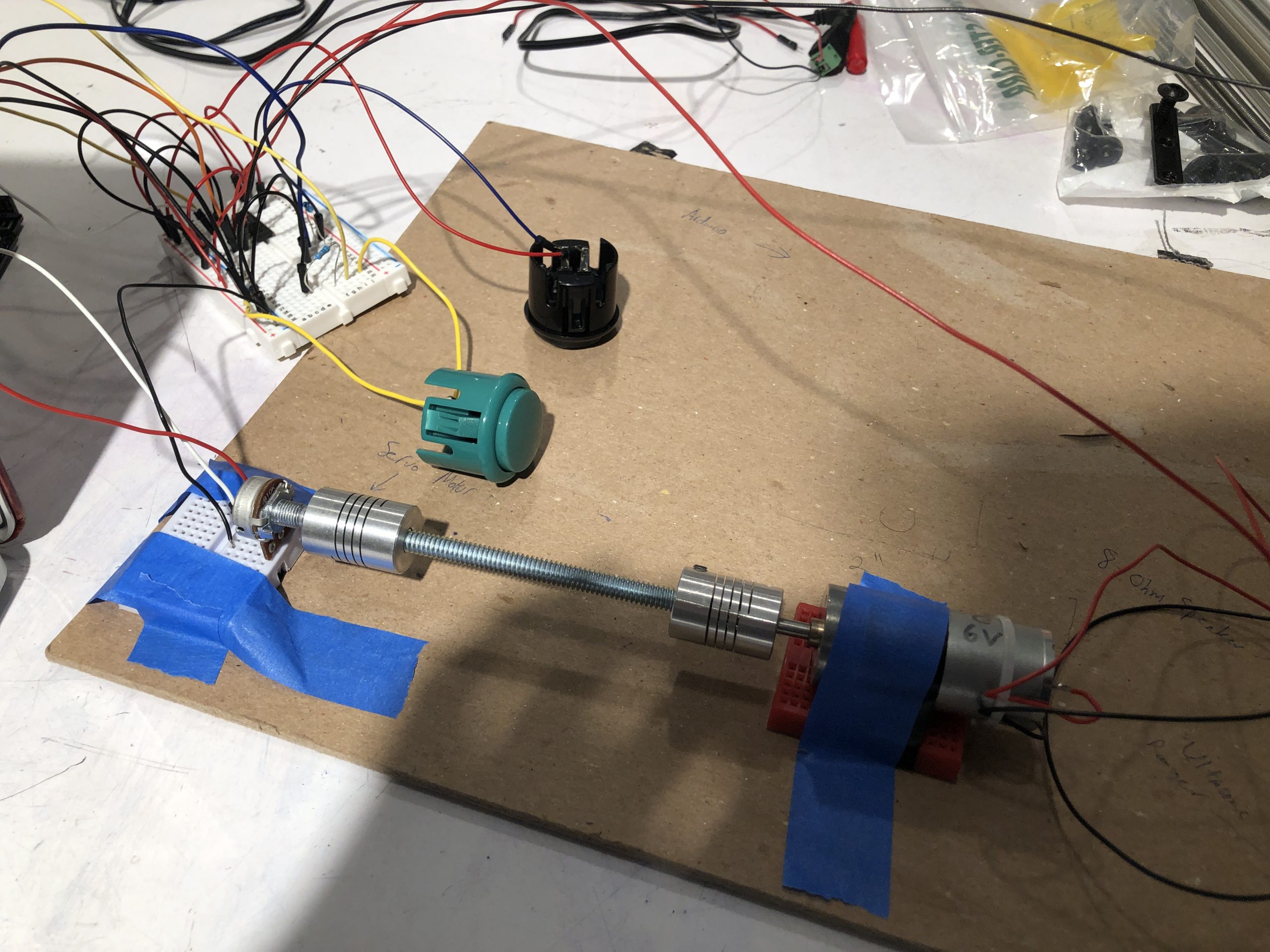
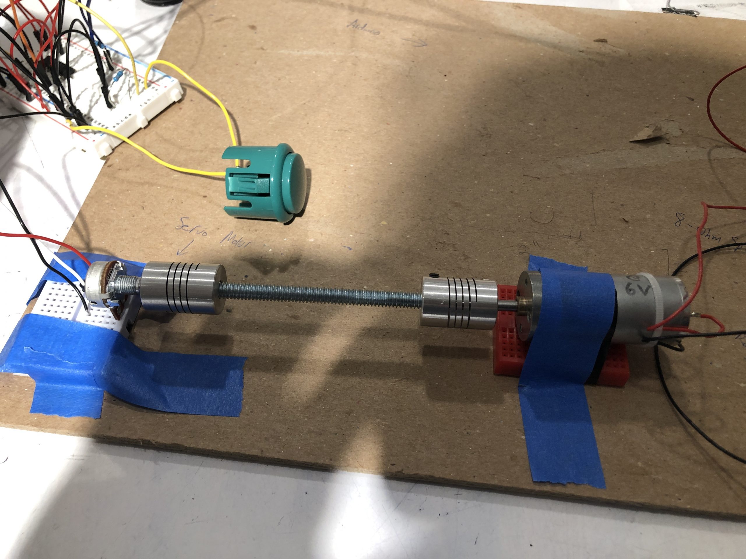
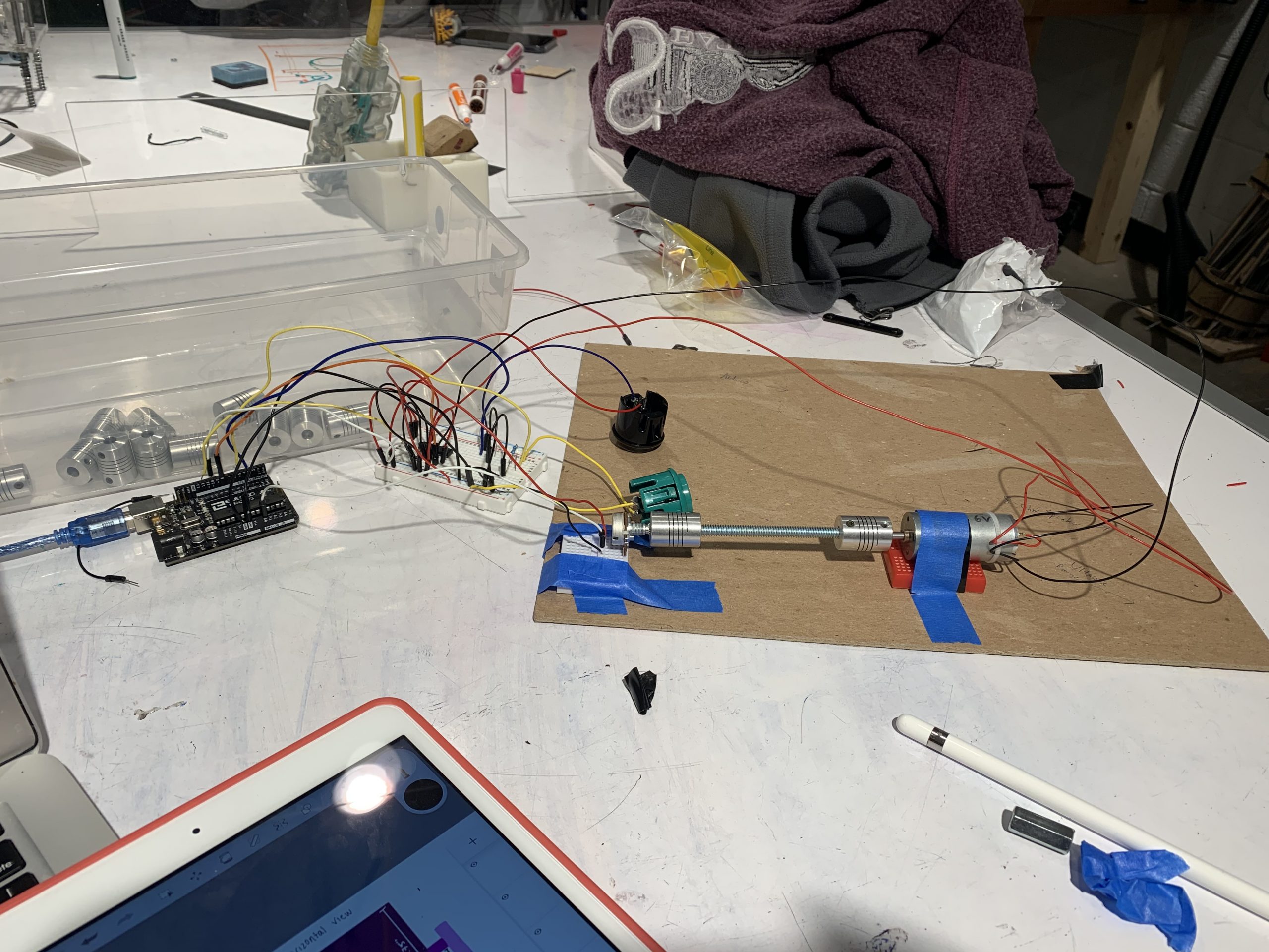
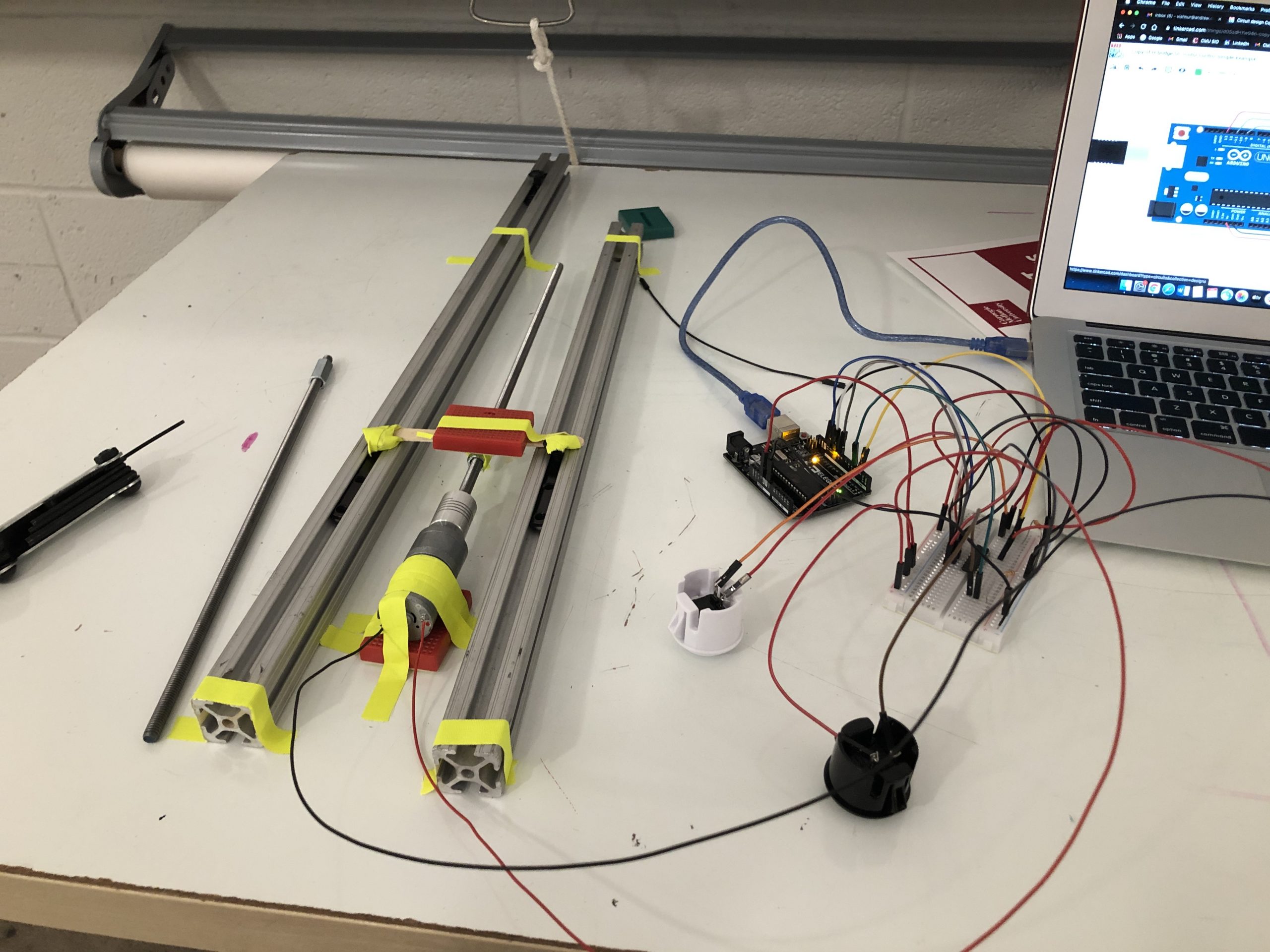
Sliding mechanism
Questions we wanted answered:
- Can the screw securely rotate, and will the nut rotate or stay put?
- How complicated is it, coding wise, to implement the forwards/backwards sliding?
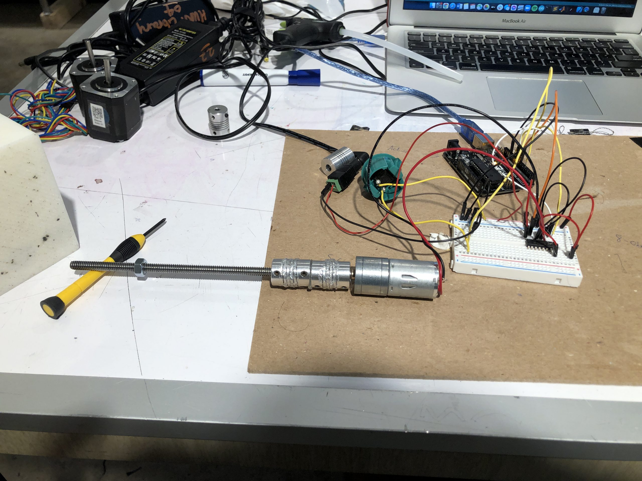
We also used a DC motor for the sliding mechanism. The motor was connected to a long screw, which, when rotated, would cause a nut to slide forward and backward along the screw. The contraption was bolted onto this nut, so the entire thing could slide back and forth with just the press of a button.
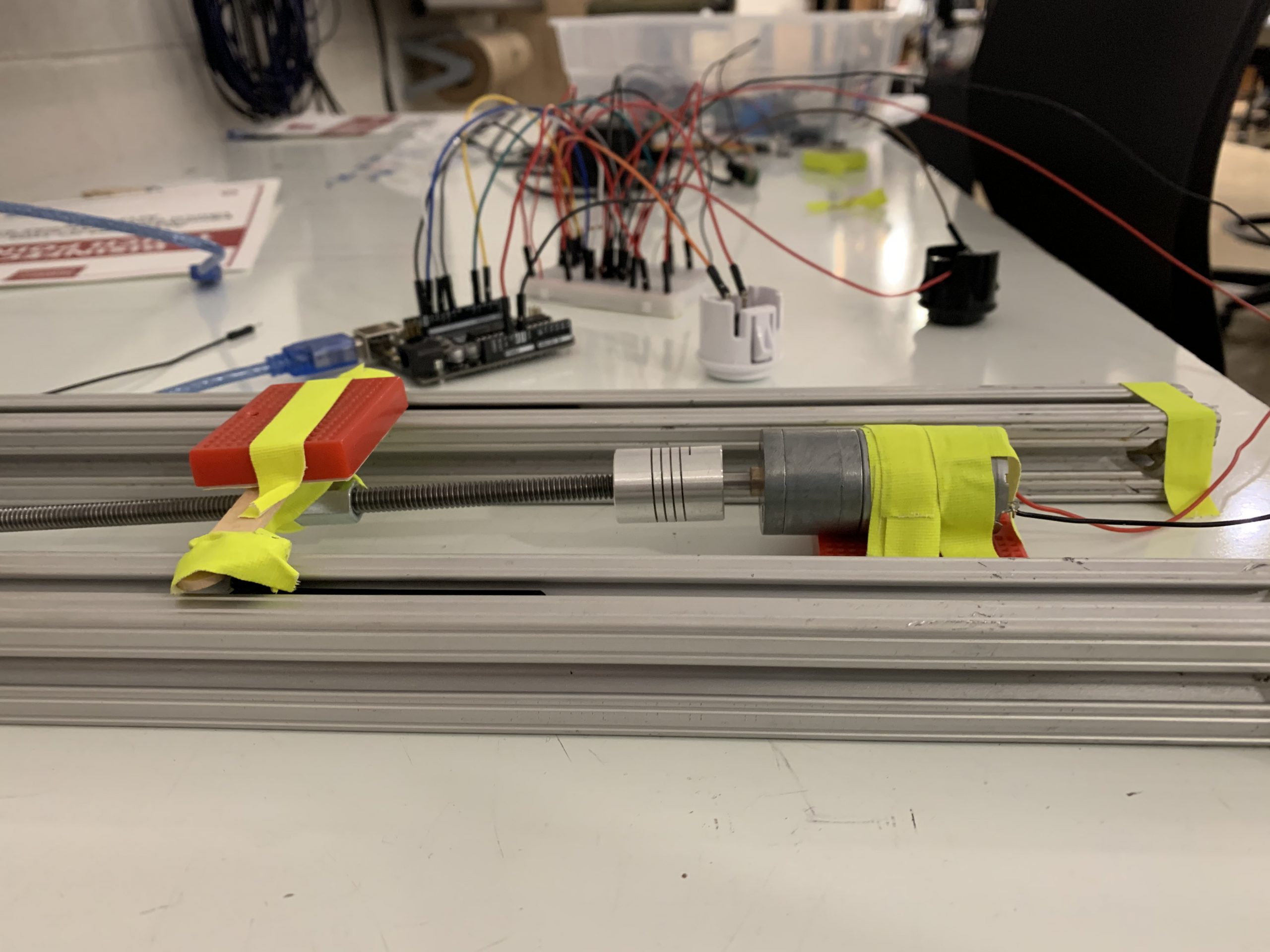
Horizontal view of slider
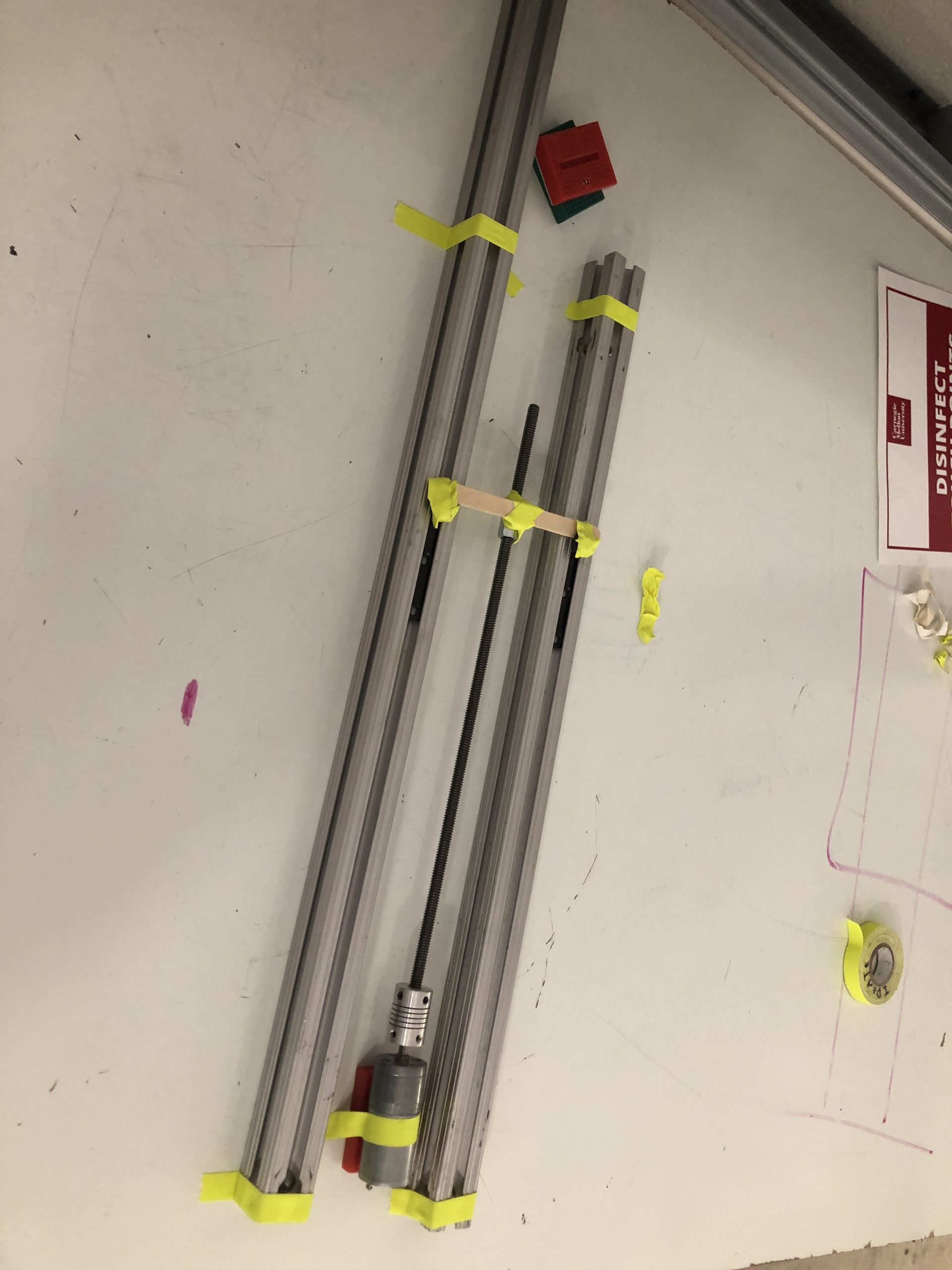
Aerial view of slider (i.e. the actual sliding portion the breadboard was attached to)
Process Images:
First draft plan of slider and rotation mechanism, visualized
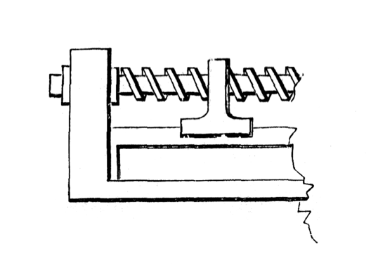
Mechanics of the slider (rectilinear motion of nut produced by rotation of screw). Src: http://507movements.com/mm_103.html
Slider mechanism in its early stages. To stabilize the screw, we thought we had to glue two screw holder together, but soon realized each holder could be secured with small screws.
Sketch of Initial Plan for rotation portion
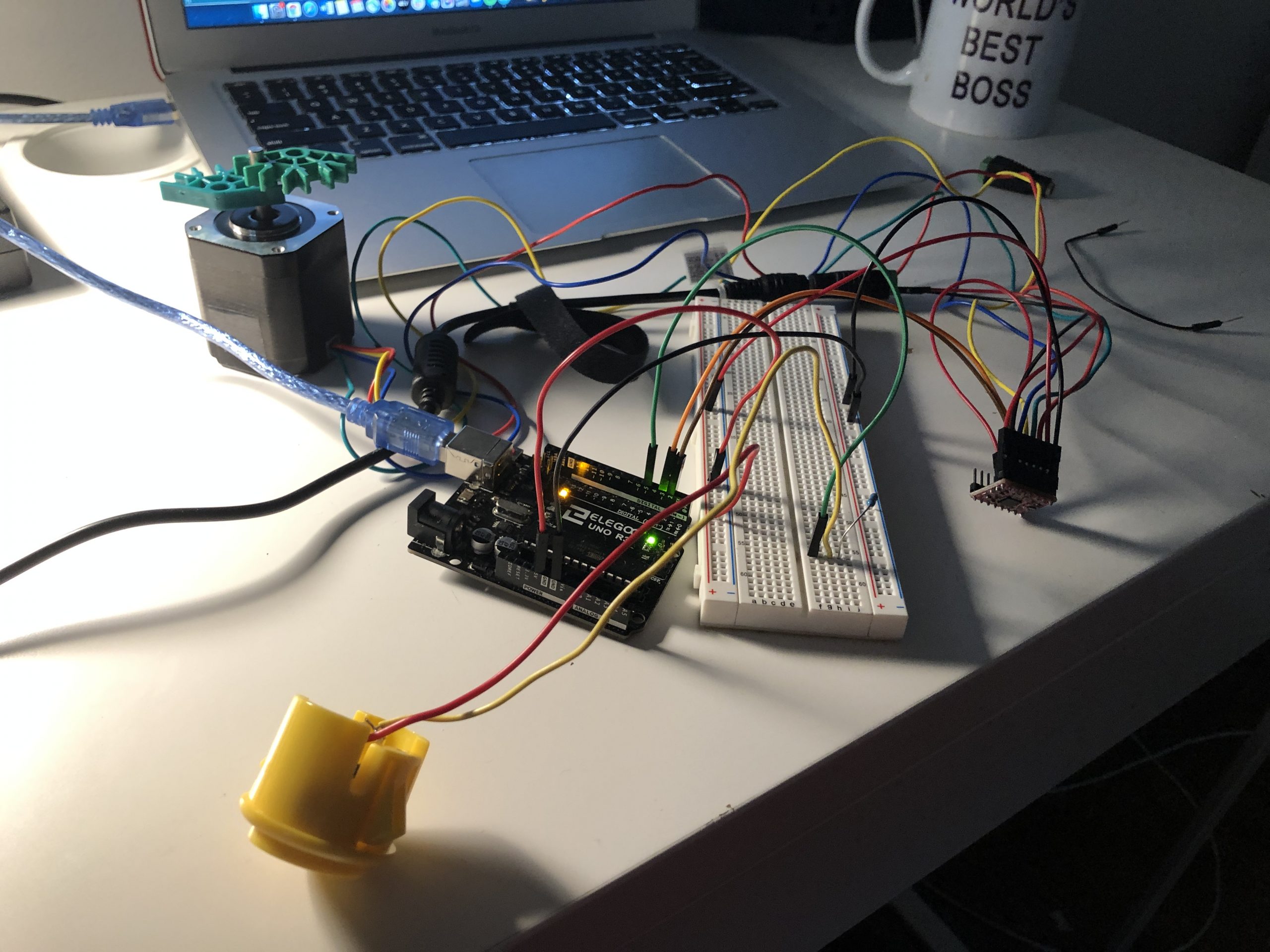
The rotational mechanism in its early stages. I wanted to understand how a DC motor worked, how fast it could spin, and observe the change in the direction of the motor
For rotation, we also experimented with using a stepper motor, under the assumption that it was more powerful and had more torque; however, we scrapped this because it was hard to control the position of the motor.
Discussion:
By the time I started on these prototypes, we had a general sense of the mechanical design of the project. I was more concerned with how the motor would interact with the other parts of the project. While I discovered that the code itself was not very complicated, it was imperative that we had all the parts of the project available, so we could see how certain sections fit together. For the rotational portion, especially, I was able to answer the question of what electronic components (i.e. DC Motor, Potentiometer) I would need to implement the controlled angling.
We also had to grapple with questions like how much force the device could handle. This was especially evident with the rotational component. While I was able to connect up the motor to the potentiometer, I did not realize how powerful the motor was, until it yanked the potentiometer out of its wiring. As a result, I had to be very careful when scrutinizing the allowable range of rotation, especially when we had constructed the full structure around the rotational component.
The sliding mechanism was easier, but we still had to ensure that the screw could securely rotate; if it was loose, the nut would not be able to move up down smoothly. This had less to do with the code, and more with making sure we tightly screwed in the rod holder. With my prototype, I was also able to do a quick demonstration of how the nut would stay in the same orientation while the screw turned, and would slide along the screw, which meant we could attach any object to it that we wanted to slide (as evinced by the “sliding” red breadboard). Overall, my prototype certainly relied on a clear picture of the final product, as we had to make sure powerful components such as the DC motor did not clash with the more sensitive laser-cut wood structures in the project.
Sunjana and Julia
We were trying to answer these questions with our model.
- What mechanical components would Haleigh like in her adjustable platform? Does she want to be able to slide the platform back and forth? Does she want to control the angle of the platform’s tilt?
- Confirmation of what kind of devices would Haleigh be placing on the platform/their sizes?
- How would Haleigh like to control the movement of the device? Would she prefer pressing down on buttons, or would she like to use a joystick?
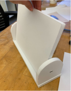
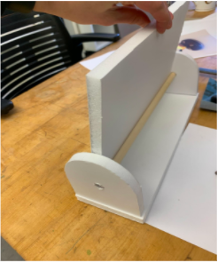
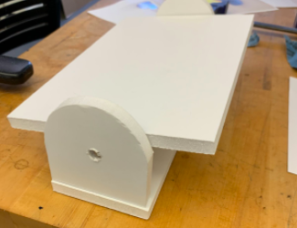
Around the time we were meeting with Haleigh, we were aiming for our platform to be able to both slide back and forth as well as angle horizontally and vertically. However, we realized that mechanically implementing this would be extremely complicated, so we wanted to make sure that Haleigh actually wanted these capabilities before we spent weeks putting together the mechanisms for them. For our prototyping meeting with Haleigh, we decided to build a “feels-like” prototype with which we could manually simulate both sliding and angling, and then let Haleigh decide, over video call, which capabilities she wanted, if any.
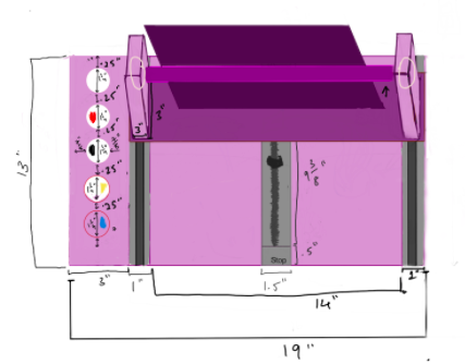
Below are images of our prototype. On the call, we manually angled the platform, which was attached to a pivoting pole through tape, which acted as a hinge. We also manually pushed the platform back and forth along some 20/80 aluminum extrusions. The pieces that slid through the extrusions were popsicle sticks attached to the platform. Haleigh then confirmed that she would prefer the platform to have both angling and sliding capabilities. As for how to control the platform, she emphasized that she would prefer to press down on pushbuttons, as she would have a hard time making a fist to grip a joystick, and she made it clear she would want to control both sliding and angling with pushbuttons. She also confirmed that she would want the buttons to be placed to the side of the device, and that the top of the platform should be about 14 to 15 inches off the desk when it is fully vertical. Finally, she told us that she would only be placing small items (i.e. Kindle, phone) on the platform, and she requested a ledge so that her items wouldn’t slip off.
Vertical angling view of prototype platform
Axle the platform rotated on, we attached the two components with tape for the demo
Horizontal angling of platform/scale photo
We ended up using all of Haleigh’s recommendations in our final version of the project. We placed the buttons on Haleigh’s right hand side after later confirming she has little mobility in her left hand and mainly uses her right, and we designed the platform to angle and slide, to only be able to handle small devices, and to have a ledge. During the prototyping process, we were most surprised by how mechanically complicated implementing the motions was. The three of us have little to no experience with mechanical engineering, and thus we initially only took into account the difficulties of programming and designing the look of the device. It was during the prototyping phase that we learned that we needed rotating rods with sliding screws that didn’t rotate, as well as a means of attaching the platform to the two rods we needed, one for sliding and one for angling. We fleshed out the latter portion in the weeks after the prototype meeting.
Process:
The Final Design of our Product
Process Photos
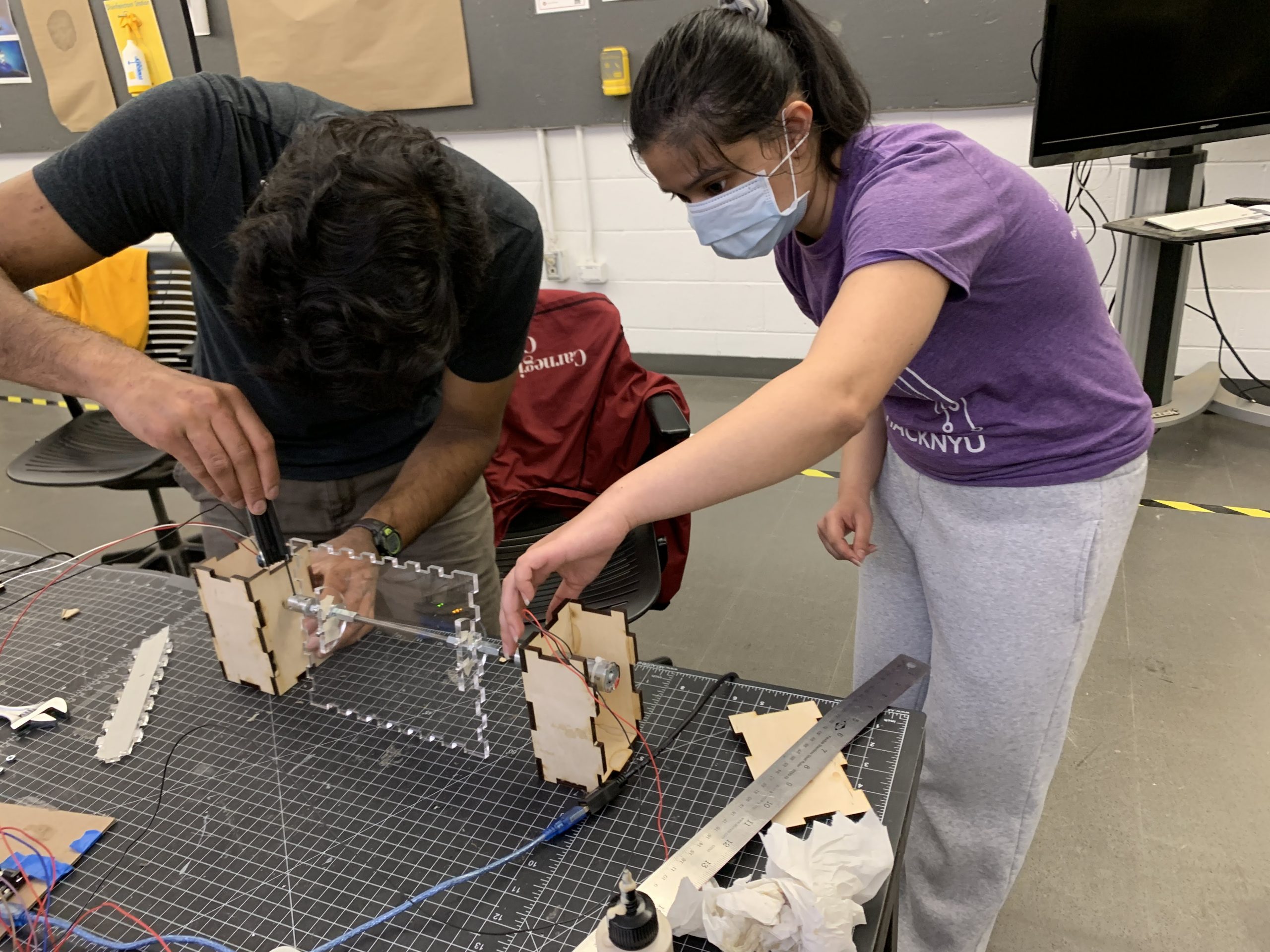
Sunjana and Vishnu working to put together electronics and physical components
Assembling the platform
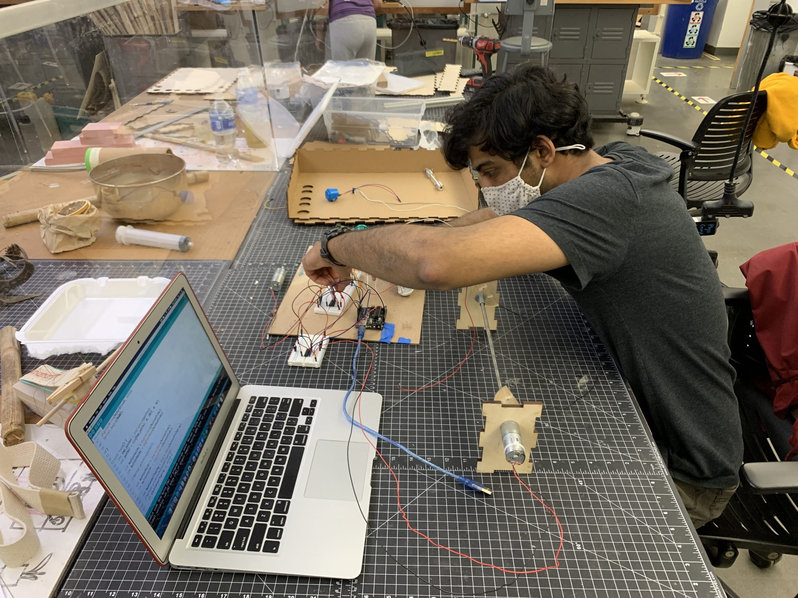
Vishnu finalizing the electrical components
Cardboard prototype of the encased nut mechanism
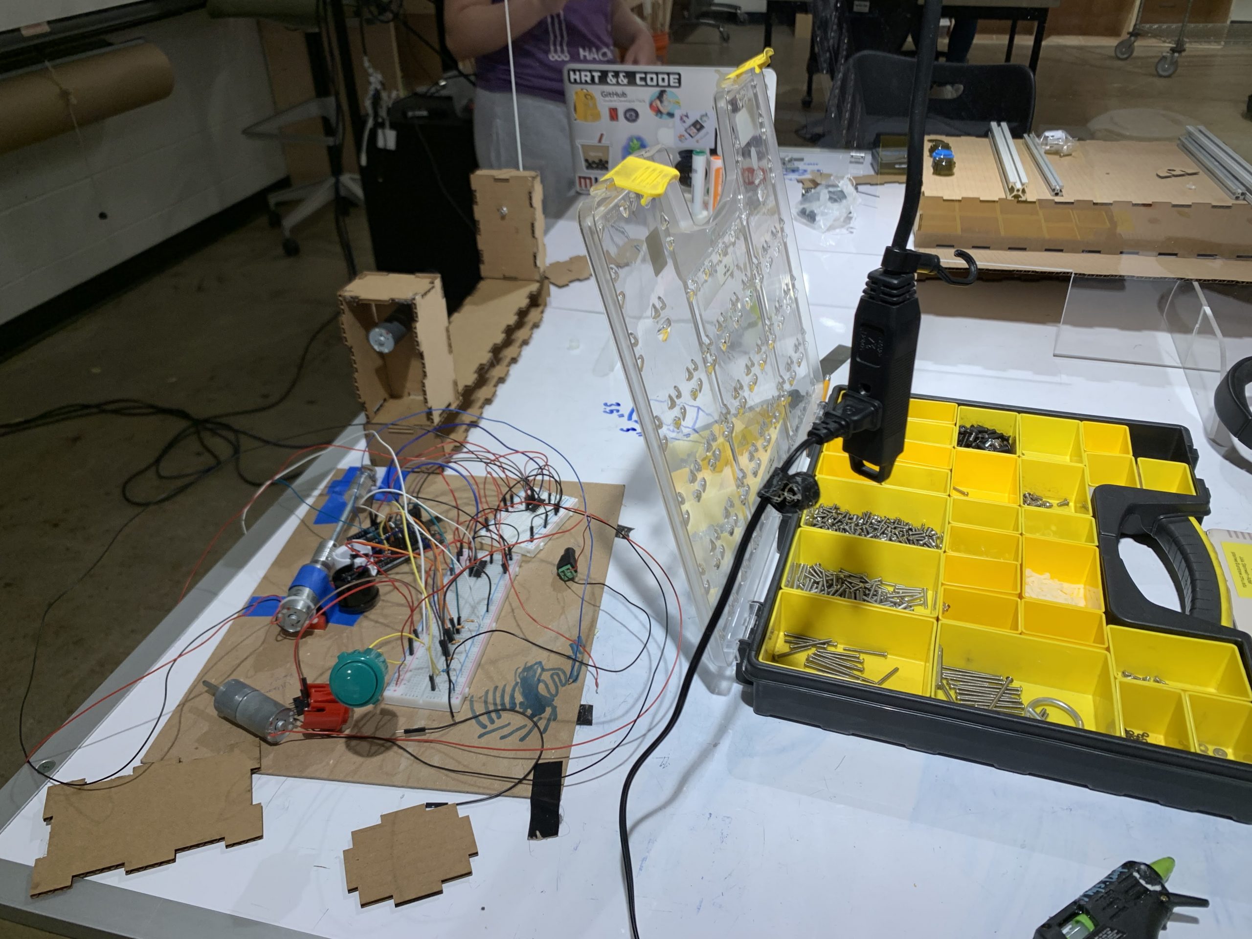
Our chaotic work bench!
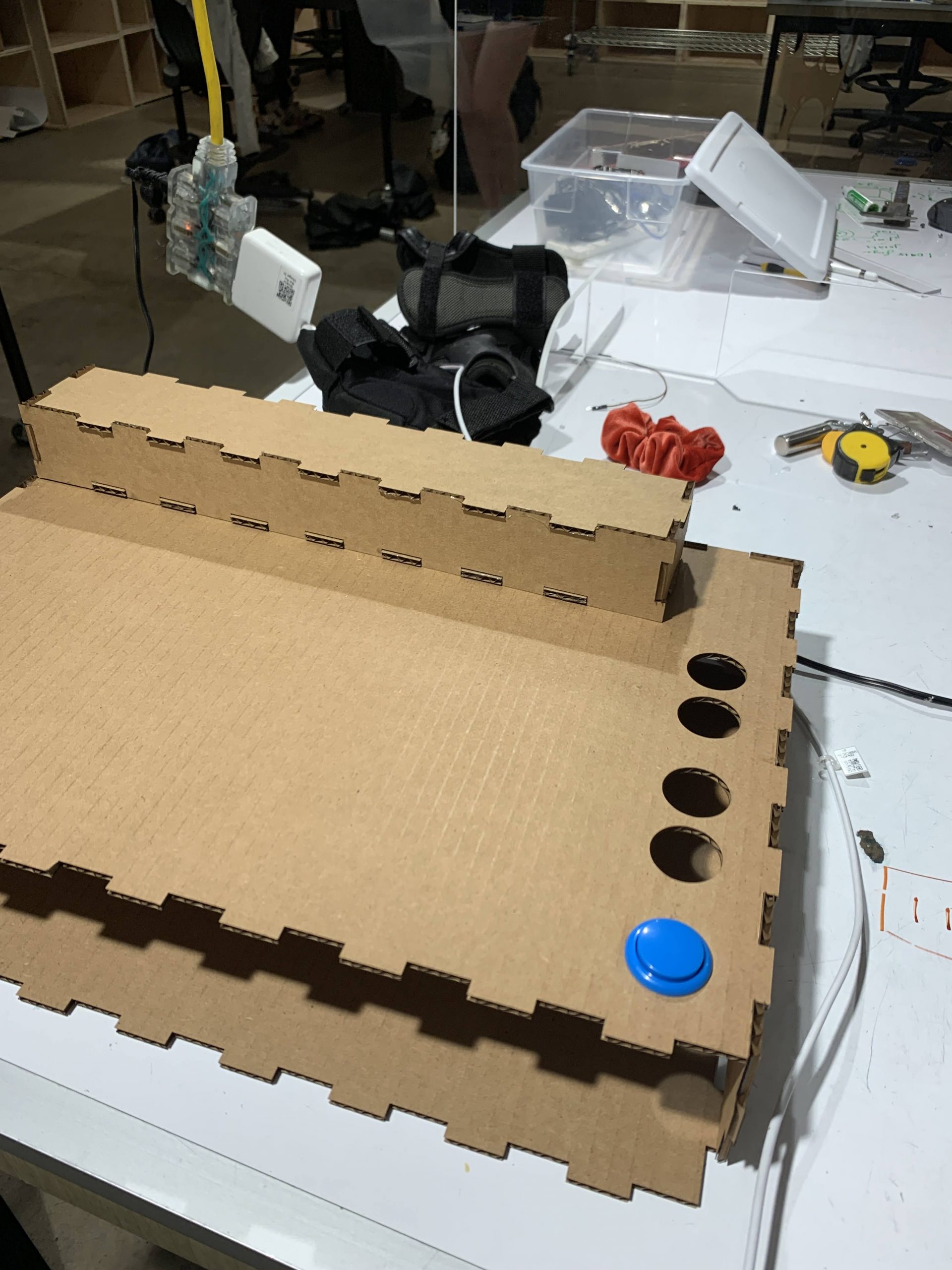
The laser-cut cardboard physical housing let us test that everything fit as intended before we cut more expensive materials.
Retrospective Process Reflection
In retrospect, the decision to pursue such a complex mechanical device dominated the course that this project took, essentially steering this assignment to take a more mechanically focused route rather than a computationally driven one. As the project developed, we chose to continue our pursuit of both angling and forward and backwards motion within our device. While in the end we technically got both of these functions working, it could have potentially been more robust and equipped to solve the problem if we had chosen to focus on just angling the platform.
It is hard to say what a “mistake” is in this context, but I suppose allowing laser cutting to happen so late on in the process prevented us from making refinements to the physical form which led to the final model being a bit clunkier than what might be practical. That being said, one could argue that within the scope of this project, we only had time to make one physical iteration. Other more technical mistakes in this process included some motors being wired backwards, some wooden parts being glued in the wrong place, and the selected motor not being able to hold the final platform. The most resistance we faced in this process was a result of not having a concise and centrally located plan, so when problems arose, it took a lot of energy to figure out what exactly was wrong and what else that impacted.
Due to the mistakes mentioned, our group learned the importance of central diagrams and common reference materials that allow each member to work on the same page. We discovered that it was difficult to refer to particular components of our complex system since none of them were formally named. Moving forward, I think we will make efforts to prioritize system schematics and diagrams with concrete labels to allow for easier problem solving throughout the process.
Another important discovery is an acute appreciation for mechanical engineers. We all learned to value the difficulty of designing functioning mechanisms that _efficiently_ result in an intended motion. Without a mechanical engineer on our team, we had a very hard time thinking about all of the issues of our mechanical solutions before we made them and had a looming fear that there were more efficient solutions. Ultimately, we learned that mechanisms are very, very hard to execute well.
Scheduling
The process of managing this work collaboratively was a challenge. Vishnu was essentially in charge of the electronic and computational execution, Sunjana was the project manager and main mechanical engineer, and Jubbies spent most of her time on physical fabrication and engineering the mechanisms. Although we took the time to flesh out our Gantt chart and update it as we started out the process, it was not entirely representative of our final work timeline since several components took longer than anticipated.
Our divergence from the schedule was in response to designing the system taking longer than planned and to unforeseen dependencies within the project development. For example, we realized that we couldn’t produce the final laser cut box design until the inner mechanisms and components were essentially finalized, which was not the case until near the end of the project. This meant that the box design and laser cutting happened later than initially planned which caused minor chaos.
Conclusions and Lessons Learned:
Salient findings from the final critique:
The feedback we received tended to be favorable towards the physical layout of our project, the mechanical design, and the sliding motion of the platform.
As for points of improvement, one major verbal critique we received was that our platform should use clamps to hold the item in place while it tilts. The critiquer, who was one of the clients, showed a similar device they had at home, which was a clamp that could grip around multiple objects. We found this to be useful because we hadn’t considered a case where the platform would be holding something thicker than the ledges designed to “hold” it. Additionally, we hadn’t considered cases where the item’s height was greater than the height of the platform, causing it to potentially slip off if the platform was suddenly angled.
Another critique we found useful was that “different shapes of buttons would be nice to differentiate between functions, since a row of circular buttons can be confusing to memorize”. During the weeks of project building, we focused on choosing buttons that could be easily pressed by Haleigh, and were not too concerned with how Haleigh would be able to differentiate which buttons belonged to which move. However, if we were to expand this project further, we would design arrow buttons for “up” (sliding away from Haleigh), “down” (sliding towards Haleigh), as well as a long rectangle for “horizontal” (platform going horizontal), as well as a tall rectangle for “vertical” (platform going vertical).
Furthermore, we agreed with the critique that our current product was too bulky, specifically that we “could likely make it smaller especially if it needs to fit on a desk”. Throughout the work period of this project, we definitely focused more on getting the mechanical components and the code to work together, as well as creating some design that could work with Haleigh’s requirements (i.e. having buttons on her right side, having it fit her tray). In the future, we could limit the range of sliding to a range which Haleigh is likelier to use (in order to reduce width of the setup from 13’’), and we would not make the box that slid along the 80/20 aluminum extrusions so thick since it didn’t hold anything.
Finally, we found critiques concerning the exposed portions of the device. Specifically, these critiques were “It’s problematic to have a ‘tray’ with exposed moving parts. Stuff will fall into the tray and get things gunked up.”, and “Also having the exposed motor for the linear positioning system might be problematic.” Since we only put the final pieces of the device and connected the arduino/wires with the mechanisms on the last day, we left several parts of the device “exposed” so we could make last minute changes to the wiring, and we didn’t have time to create extra housing for the motor that rotated the “sliding” rod. In the future, we would definitely create housing for this piece so it isn’t exposed, and we would place the motor on the side that is opposite to the user. Additionally, we would seal the sides and the tops of the two boxes connected by the angling rod.
Thoughts on the experience of working remotely from our teammates as well as our client:
Admittedly, working on this project in a pandemic proved to be challenging. Given that the class is focused on tangible creation, which requires in-person attention and care, designing and implementing a project of large scope was no small feat. Compounding this challenge was the fact that we could not meet our client, Haleigh, in person. This proved to be a crucial hurdle to clear, as our project was very mechanical, as opposed to mostly electrical (as had been our previous projects).
For instance, we had to interview Haleigh over Zoom, and in order to get a clear picture of her problem, we had her mother move the camera around to show us her tray, upon which we would place our device. However, we also had to note down Haleigh’s physical constraints, including how far she could reach her hands, and also the length and width of her desk. All these physical measurements would have been much easier to take had we been able to meet with Haleigh in person.
In retrospect, this project was not well-suited to remote work. The only aspect that ran fairly smoothly was the coding portion; however, even that section required at least a partial physical mockup in order to see results, and that relied on meeting to laser cut and assemble the relevant pieces. Finally, we could have greatly streamlined communication in this remote environment. We have been communicating via iMessage, and at times not everyone was responsive with their updates. In the future, we need to enforce strict times when we send updates on our project progress, and do a better job of holding each other accountable if someone falls short.
Major takeaways from the experience of working with a person with a disability:
Technical Details:
Schematic and Block Diagram:
Block Diagram:

Schematic:

Code:
/*Final Project: Motorized Device Holder
 * Team Yews: Vishnu, Julia, Sunjana
 *
 * Description: This code controls both the sliding and rotating mechanisms of the contraption.
 *
 * The sliding mechanism is driven by a DC motor, which controls a rotating screw.
 * As the screw rotates, it moves a plastic piece along, forwards or backwards.
 *
 * The rotating mechanism is also driven by a DC motor, albeit attached to a potentiometer.
 * The DC-potentiometer setup acts as a feedback loop; as the motor turns, it also controls the potentiometer
 * dial, which outputs a mapped value in software (0 to 360). When the value hits a certain threshold,
 * the DC motor stops rotating, thus serving as an upper and lower bound on the range. The clockwise and
 * counterclockwise rotation of the DC motor ultimately controls the device holder's orientation.
 *
 * Pin Mapping:
 *
 * Arduino Pin:     Type:           Description:
 * ---------------------------------------------
 * 10               output          motor A (rotational)
 * 8                output          motor B (rotational)
 * 12               output          motor driver (rotational)
 * 11               output          motor A (translational)
 * 9                output          motor B (translational)
 * 13               output          motor driver (translational)
 * A0               input           potentiometer
 * 7                output          pushbutton (forward)
 * 6                output          pushbutton (backward)
 * 5                output          pushbutton (clockwise)
 * 3                output          pushbutton (counterclockwise)
 */


//Set up pin mappings and initial variables

//Rotational motors
int motorAr = 10;
int motorBr = 8;
int motorDriveR = 12;

//Translational motors
int motorAs = 11;
int motorBs = 9;
int motorDriveS = 13;

//Potentiometer (for restricting rotation of platform)
int potPin = A0;

//Clockwise and counterclockwise buttons
int buttonPinAr = 7;
int buttonPinBr = 6;

//Forward and backward buttons
int buttonPinAs = 5;
int buttonPinBs = 3;

//Variables to track button presses (rotational, translational)
bool prevAr = false;
bool currAr = false;
bool prevBr = false;
bool currBr = false;

bool prevAs = false;
bool currAs = false;
bool prevBs = false;
bool currBs = false;


void setup() {

  //Set up initial pin modes
  pinMode(motorAr, OUTPUT);
  pinMode(motorBr, OUTPUT);
  pinMode(motorDriveR, OUTPUT);
  pinMode(potPin, INPUT);

  pinMode(motorAs, OUTPUT);
  pinMode(motorBs, OUTPUT);
  pinMode(motorDriveS, OUTPUT);

  //Set up drivers
  digitalWrite(motorDriveR, HIGH);
  digitalWrite(motorDriveS, HIGH);
  Serial.begin(9600); //print feedback

}


void loop() {
  int tmp_potVal = analogRead(potPin);

  //Restrict potentiometer value between 0 and 360 (a circle)
  int potVal = map(tmp_potVal, 0, 1023, 0, 360);

  int buttonValAs = digitalRead(buttonPinAs);
  int buttonValBs = digitalRead(buttonPinBs);

  int buttonValAr = digitalRead(buttonPinAr);
  int buttonValBr = digitalRead(buttonPinBr);

//If button Ar is pressed, tilt motor into "vertical" position
  if (buttonValAr == HIGH and buttonValBr == LOW) {
    if (prevAr == false) {
      currAr = true;
    }
    //Upper limit of potentiometer = 70º
    if (potVal < 70) {
      digitalWrite(motorAr, HIGH);
      digitalWrite(motorBr, LOW);
    }
    //Once motor reaches 70º, stop
    else if (potVal == 70) {
      digitalWrite(motorAr, LOW);
      digitalWrite(motorBr, LOW);
    }
  }

//If button Br is pressed, tilt motor into "horizontal" position
  if (buttonValBr == HIGH and buttonValAr == LOW) {
    if (prevBr == false) {
      currBr = true;
    }
    //Lower limit of potentiometer = 0º
    if (potVal > 0) {
      digitalWrite(motorAr, LOW);
      digitalWrite(motorBr, HIGH);
    }
    //Once motor reaches 0º, stop
    else if (potVal == 0) {
      digitalWrite(motorAr, LOW);
      digitalWrite(motorBr, LOW);
    }
  }

  //If neither rotational button is pressed, motor is stopped
  if (buttonValAr == LOW and buttonValBr == LOW) {
    if (prevAr == true) {
      currAr = false;
    }
    digitalWrite(motorAr, LOW);
    digitalWrite(motorBr, LOW);
  }

  //If button As is pressed, contraption moves forward
  if (buttonValAs == HIGH and buttonValBs == LOW) {
    if (prevAs == false) {
      currAs = true;
    }
    digitalWrite(motorAs, LOW);
    digitalWrite(motorBs, HIGH);
  }

  //If button Bs is pressed, contraption moves backward
  if (buttonValBs == HIGH and buttonValAs == LOW) {
    if (prevBs == false) {
      currBs = true;
    }
    digitalWrite(motorAs, HIGH);
    digitalWrite(motorBs, LOW);
  }

  //If neither translational button is pressed, the contraption does not slide
  if (buttonValAs == LOW and buttonValBs == LOW) {
    if (prevAs == true) {
      currAs = false;
    }
    digitalWrite(motorAs, LOW);
    digitalWrite(motorBs, LOW);
  }


  //Update variables before next iteration of loop

  prevAr = currAr;
  prevBr = currBr;

  prevAs = currAs;
  prevBs = currBs;

}