TinkerCad Simulation
This simulation helped us plan our physical project. Here we have a potentiometer as the input, an RGB LED and photo-resistor as our middle step, and a pancake vibration motor as our output.
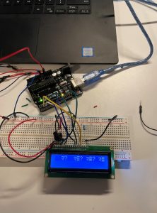
Dani’s Project

Dani’s final project
Demonstration:
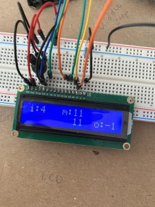
Nish’s Project
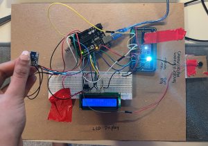
Nish’s Final Project image
Demonstration:
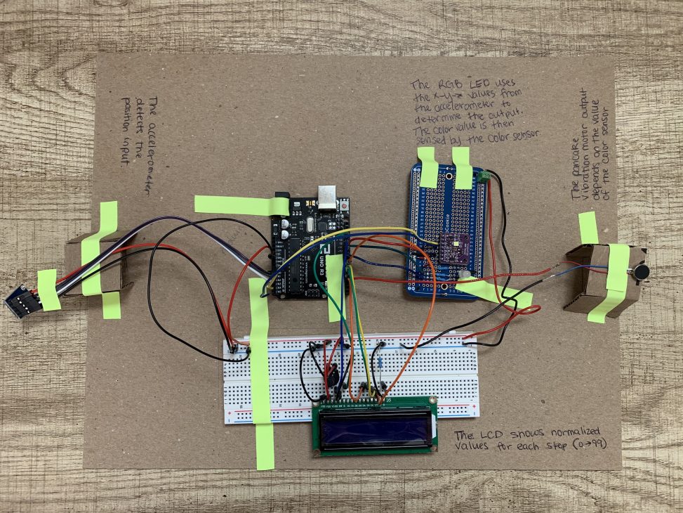
Project Images
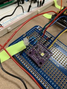
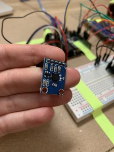
The RGB LED and the Color Sensor (purple chip) act as our middle transduction step
The accelerometer is the input to detect position change
Project Description
The user holds a position sensor and can move and tilt it in all directions. This will make and LED light up in different colors, depending on the position of the sensor. A color sensor picks up what color the LED is at that moment. The color sensor will then determine how much to vibrate the output based on what color it sees.
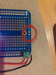
Progress Images
I thought the power/ground connections went all the way to both sides of the board, but there is a small gap at the bottom. It took me a while to realize I needed to bridge the gap to close the electrical connection.
We were getting negative values on our LCD and we realized it was because we were mapping to incorrect ranges that were causing values outside of the 0-99 range.
I wasn’t able to get the LCD to display correctly for a while. It turned out the wires weren’t matched up exactly to how I had described them in the Arduino code, and the LCD pins were not fully inserted into the breadboard. It was difficult to get the pins to stay in consistently. – Nish
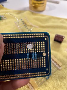
I was having some difficulty soldering because I decided to solder in the RGB LED first. However, this was a bad idea as it made the rest of the board uneven for me to solder the resistors and other components on. Therefore, a lot of the resistors look uneven and like they’re sticking out, as demonstrated in this picture. Also, even though it doesn’t really matter, I was upset that I had soldered upside down on the protoboard. – Nish
Discussion
The easiest parts of this project including the brainstorming and ideation as well as the actual wiring of the parts. We felt there was only a limited number of options for our middle step since it would be difficult to physically modulate anything in our middle step to use something like distance/distance sensor. However, upon seeing what other groups have completed, we realized we could have been more creative in this project by using outputs and motors we do have to create a physical middle step, perhaps something similar to our wind sensor idea but more practical for this class. However, using color as a middle step did invoke some challenges as well that we didn’t think we would run into.
Though the soldering overall was easy, Nish did learn something that should have been intuitive. Although RGB LEDs individually have different current values they need in order to not blow up, if you use different resistors on each one, the intensity of each color will show up differently. She had already soldered in her resistors when she realized this, and this mistake was reflected when the color sensor was not able to sense as much red as should have been outputted in the LED.
Learning how to use the color sensor was an interesting challenge, though not a difficult one. Since we were using a sensor that was not a part of our kit, there wasn’t necessarily a module that described how to wire it and code it, so our team had to use our own research to find our model and other projects that had used the same sensor. Since this is a common sensor it was not that difficult to find Arduino code online that we could model ours after. While we probably don’t understand why it’s coded in the way it is and didn’t fully utilize all the functions, we were able to successfully sense the output of our RGB LED.
The most difficult part of our project was figuring out how to go from three inputs (X, Y, Z orientation) to just one final output, where different combinations of the three inputs would lead to a meaningful differences in the final output. Several different input positions can lead to the same output, as we discovered that the X, Y, Z inputs tend to vary around the same values for the most part (between 200 and 300, though their individual ranges can go between 0 and 500). Therefore, if we mapped the entire 0 to 500 value to a 0-255 range for our RGB values, we would end up with very similar colors no matter what the orientation is, so we chose to map our X, Y, and Z values of only 200-300 to a 0-255 range for later use. However, for some reason when we tried to map to a 0-99 range for our output into the LCD, the Arduino program did not like that and we had to change our range of the X, Y, Z inputs from 200-300 to 0-500, resulting in the LCD representation for our input having a very small range that was not consistent with the rest of the numbers that had been calculated from a 200-300 range mapping. We are still unsure as to why the Arduino program did not let us map from a 200-300 range in this portion, and hope to eventually get more consistent numbers between our four outputs on the LCD.
We also ran into a problem where despite using code similar to our previous outputs to the LCD, the representation of the vibration output was coming out negative. Both of us individually solved this in different ways, with one of us using “constrain” from 0 to 99, and the other changing this output from an int to an unsigned int. While we learned different methods to solve the problem, we are still unsure of the root cause of why we got a negative output in the first place, since I don’t believe we caused any overflow and we were only working with positive numbers that had worked fine up until that calculation. Throughout these several issues with mapping, we were able to pick up handy debugging skills, such as using the Serial.print() function for both strings and variables in intermediate steps to see what our numbers were before we mapped them, and to find the appropriate typical range for each of our sensors.
We probably could have used more features of the color sensor if we had explored more. Since we were going from three inputs to one output, and our X, Y, Z ideally directly maps to an RGB value, respectively, we perhaps could have utilized the “lux” sensor. Our color sensor was able to sense not only red, green, and blue values, but also the intensity. Looking back, this may have made more sense to use it’s a more direct way of going from the color itself to a single property of the color, rather than trying to arithmetically calculate a single output value for vibration from three values of red, green, and blue. It also would have made our middle step more significant in calculating the final output, rather than just something we had to put in for this project since we definitely could have used a similar formula to directly calculate vibration from the X, Y, Z coordinates.
Functional Block Diagram and Schematic
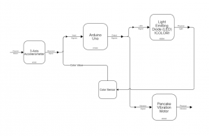
The Functional Block Diagram for our project shows a high level of the inputs and outputs.
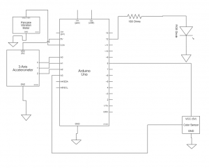
The Schematic of our project presents a more detailed view of how the components are connected to each other.
Code
#include <Wire.h>
#include "Adafruit_TCS34725.h" // for color sensor
#include <LiquidCrystal.h> // for LCD

/*

Daniela Castleburg & Nish Nilakantan

Double Transducer: Orientation to Color to Vibration

This code takes in X, Y, Z coordinates of an input sensor and maps them to RGB values which create a color outputted by the RGB LED, which is then sensed by the color sensor and mapped to a single value that represents the strength of output vibration.


Pin Table:

pin     |     mode    |   description
--------------------------------------
A0          input         x position
A1          input         y position
A2          input         z position
A4          input         color sensor (SDA)
A5          input         color sensor (SCL)
3           output        pancake vibrator
4           output        d4 LCD
5           output        d5 LCD
6           output        d6 LCD
7           output        d7 LCD
9           output        Blue LED
10          output        Green LED
11          output        Red LED
12          output        EN LCD
13          output        RS LCD


Credits for Color Sensor code: https://learn.adafruit.com/adafruit-color-sensors/arduino-code
*/


// INPUT //
// Accelerometer pins
const int accelXPin = A0; // Analog input pin for X movement
const int accelYPin = A1; // Analog input pin for Y movement
const int accelZPin = A2; // Analog input pin for Z movement

// Variables to keep track of the current positions
int accelXPos = 0;
int accelYPos = 0;
int accelZPos = 0;


// MIDDLE STEP //
// RGB LED pins
const int RED = 11;
const int GREEN = 10;
const int BLUE = 9;

/* Initialise with specific int time and gain values */
Adafruit_TCS34725 tcs = Adafruit_TCS34725(TCS34725_INTEGRATIONTIME_700MS, TCS34725_GAIN_1X);


// OUTPUT //
const int PANCAKE = 3;

// initialize the library by associating any needed LCD interface pin
// with the arduino pin number it is connected to
const int rs = 12, en = 13, d4 = 4, d5 = 5, d6 = 6, d7 = 7;
LiquidCrystal lcd(rs, en, d4, d5, d6, d7);

// Other variables
const int WAIT = 200;
unsigned long lastTime = 0;


// MQTT
int inVal, outVal;

void setup() {
// begin serial communication
Serial.begin(115200);
Serial.setTimeout(50);

// finding the color sensor
if (tcs.begin()) {
Serial.println("Found sensor");
} else {
Serial.println("No TCS34725 found ... check your connections");
while (1);
}

// RGB LED as output
pinMode(RED, OUTPUT);
pinMode(GREEN, OUTPUT);
pinMode(BLUE, OUTPUT);

// Setup the accelerometer inputs
pinMode(accelXPin, INPUT);
pinMode(accelYPin, INPUT);
pinMode(accelZPin, INPUT);

// Pancake Vibration Motor as output
pinMode(PANCAKE, OUTPUT);

// set up the LCD's number of columns and rows:
lcd.begin(16, 2);
}


void loop() {

uint16_t r, g, b, c, colorTemp, lux;

// Get the current states of accelerometer
accelXPos = analogRead(accelXPin);
accelYPos = analogRead(accelYPin);
accelZPos = analogRead(accelZPin);
int accelAbs = sqrt(accelXPos ^ 2 + accelYPos ^ 2 + accelZPos ^ 2); // absolute acceleration for LCD

// map acceleration input to LED output
int redVal = map(analogRead(accelXPin), 200, 300, 0, 255);
int greenVal = map(analogRead(accelYPin), 200, 300, 0, 255);
int blueVal = map(analogRead(accelZPin), 200, 300, 0, 255);


// Use mqtt to get input data
// int redVal = map(inVal,0,99,0,255);
// int greenVal = map(inVal,0,99,0,150);
// int blueVal = map(inVal,0,99,0,100);
int LEDAbs = sqrt(redVal ^ 2 + greenVal ^ 2 + blueVal ^ 2); // combination of LED values for LCD

// update LED color based on accelerometer position
analogWrite(RED, redVal);
analogWrite(GREEN, greenVal);
analogWrite(BLUE, blueVal);

// data from color sensor
tcs.getRawData(&r, &g, &b, &c);
int colorSensorAbs = sqrt(r ^ 2 + g ^ 2 + b ^ 2); // combination of color sensor values for LCD

// map color sensor data to pancake input
int pancakeVal = map(colorSensorAbs, 100, 250, 0, 255);

// update pancake vibration motor based on color sensor
analogWrite(PANCAKE, pancakeVal);

// get pancake value
//int normOutput = analogRead(PANCAKE);

// normalize all variables to 0-->99 range
int normInput = map(accelAbs, 0, 500, 0, 99); // Accelerometer
int normMiddleOutput = map(LEDAbs, 0, 255, 0, 99); // RGB LED
int normMiddleInput = map(colorSensorAbs, 0, 500, 0, 99); // Color Sensor
int normOutput = map(pancakeVal,-350,350,0,99); // Pancake Vibration motor

// print information to LCD
if (millis() - lastTime > WAIT) {
lcd.setCursor(0, 0);
lcd.print("i:");
lcd.setCursor(2, 0);
lcd.print(normInput);

lcd.setCursor(6, 0);
lcd.print("m:");
lcd.setCursor(8, 0);
lcd.print(normMiddleOutput);

lcd.setCursor(8, 1);
lcd.print(normMiddleInput);

lcd.setCursor(12, 1);
lcd.print("o:");
lcd.setCursor(14,1);
lcd.print(normOutput);

outVal = normOutput;
transmitSerialSignal();

lastTime = millis(); // update timer variable
}
}


// Mqtt functions
void serialEvent(){
while(Serial.available() > 0){
inVal = Serial.parseInt();
}
}

void transmitSerialSignal(){
Serial.println(outVal);
}