
The most successful Tinkercad circuit we built, for testing and learning the LCD screen and the LiquidCrystal library. See below for our full Tinkercad circuit and why it didn’t work.
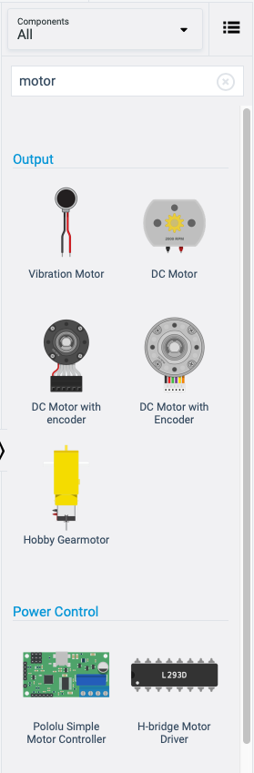
To begin this assignment, we discussed various ideas of how we could transduce orientation to light. After a couple hours of excited general brainstorming, we found it very helpful to use then maker cards to narrow down our conversation in terms of input and output. This focus allowed us to see what was necessary in the middle steps of the operation , and what parts may lend themselves well to working together.

An overview of our 3 more refined ideas
Our favorite of the 0ur 3 more refined ideas was the following:
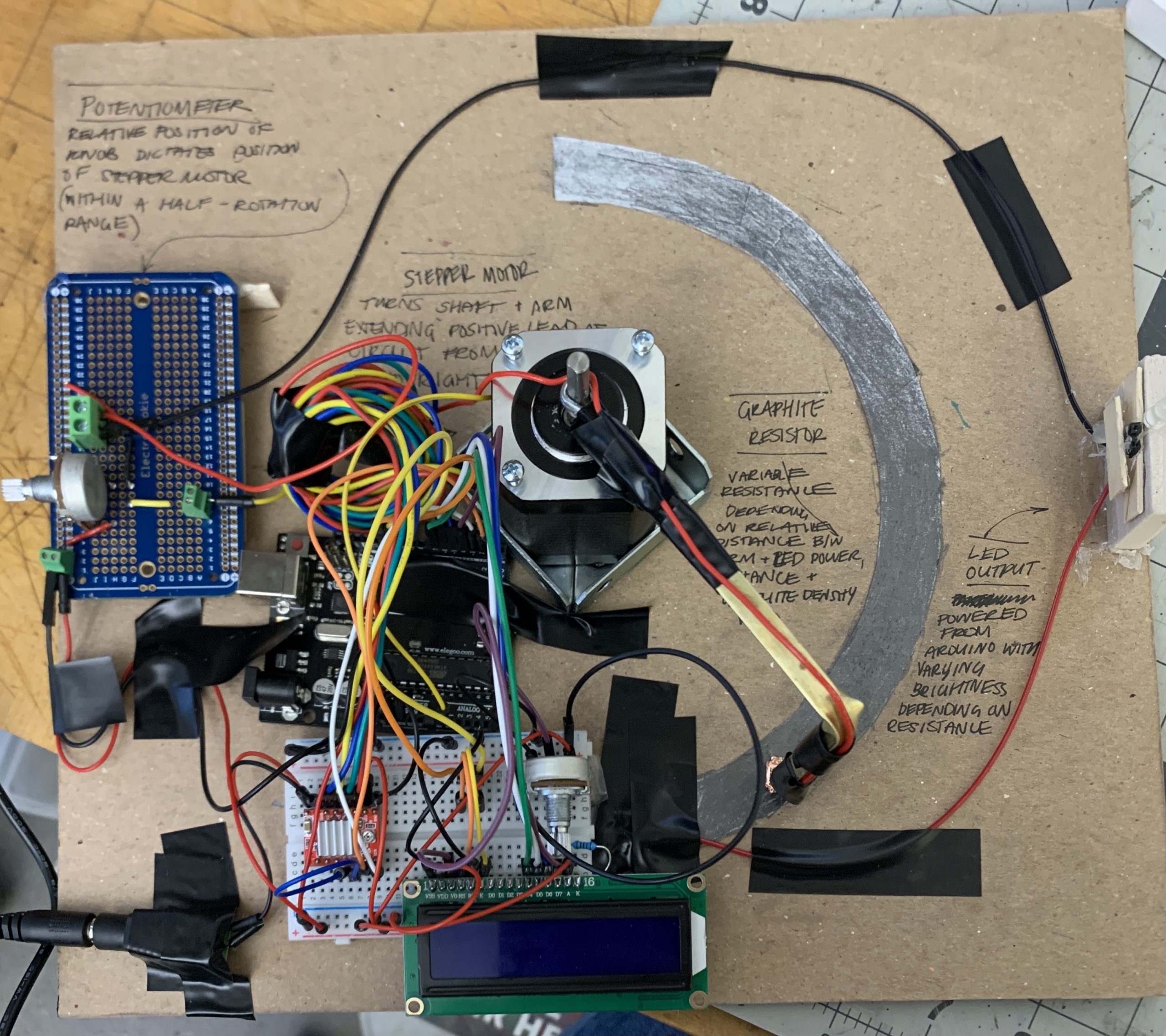
A potentiometer sets the angle for a servo for a stepper motor. A cable sticking out from the motor turns with the motor and glides on a layer of graphite drawn around the motor. A current is always flowing through the graphite, and depending on the position of the cable along the graphite trail, it’ll measure more or less current. Essentially like a homemade potentiometer whose position is determined by a stepper motor. Depending on the current read by the cable, an LED lights up more or less.
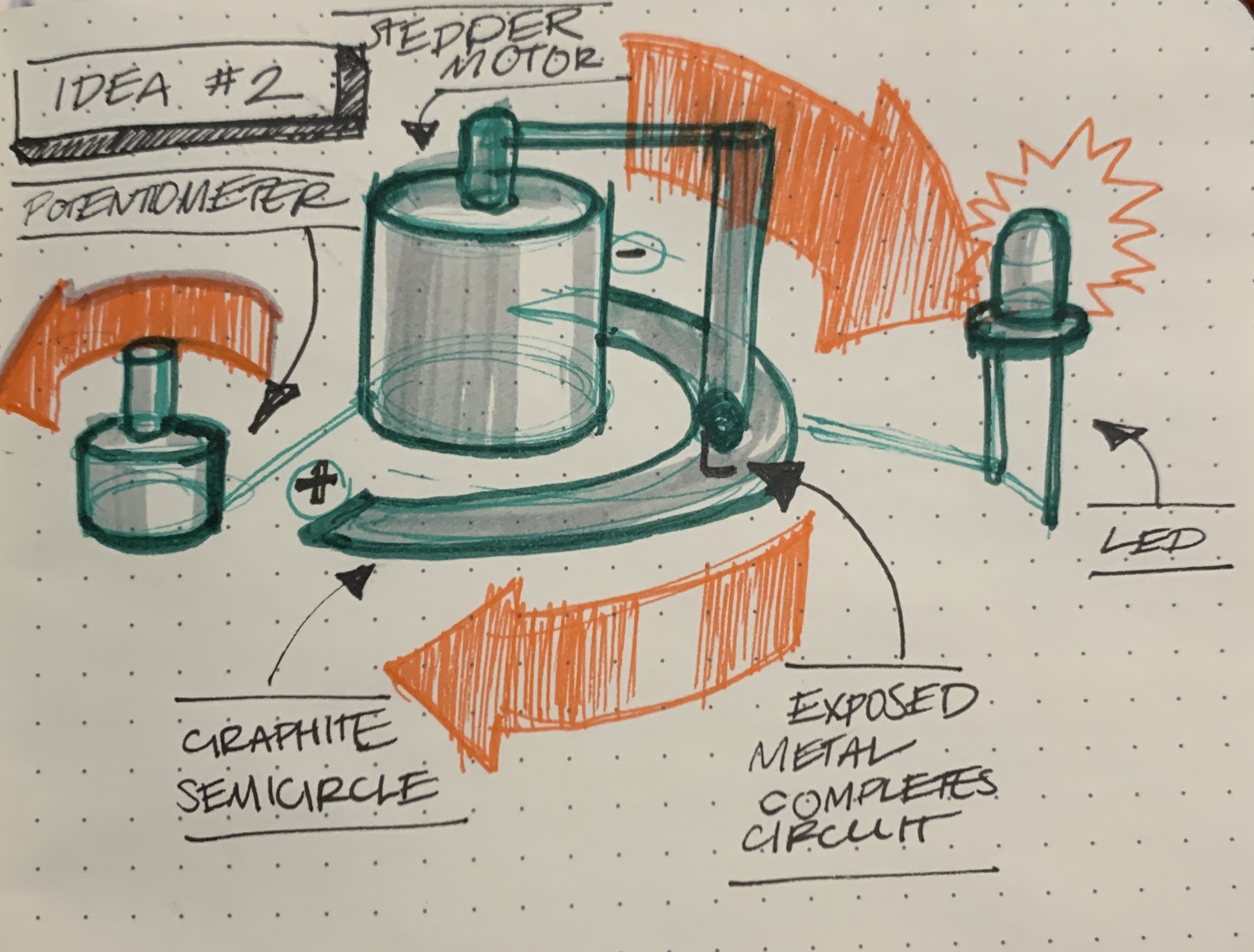
Jubbies’ concept sketch for our idea
We had gotten some good feedback from our professor as well, since this idea seemed to be a good balance between exciting and feasible. To proceed forward, we broke down our problem into several steps so we could focus on individual components before be assembled them together . The first step we needed to confirm was working independently was the one that was most unfamiliar – using a graphite resistor. To learn how to do this, Jubbies used YouTube to find a concise demonstration of this idea.
The following video was very helpful as it demonstrated some of the affordances of using graphite circuit .
Using this video as guidance, Jubbies recreated this graphite circuit with alligator clips in a 9-volt battery. This demonstration proved successful, although there was not as much variance in the light as was desired. We found that this issue was resolved as we eventually used a longer graphite resistor.
Demonstration of the graphite circuit
After proving that the graphite circuit could work, the next issue to tackle was controlling the stepper motor accurately with a potentiometer. This pursuit proved to be far more difficult than we first predicted. A huge barrier that we had to figure out how to overcome Rose making the stepper motor turn the correct direction. For some reason the stepper motor seems to only cumulatively turn to the right no matter the direction that the potentiometer was turned. it was as if the stepper motor turn only two the amount that was equivalent to the total value that the potentiometer was turned , regardless of whether that value was left or right. We tried editing the code and checking our wiring for hours, but none of this seemed to help.
here’s an example of the potentiometer moving to stepper motor only to the right depsite the direction that the potentiometer turned.
It wasn’t until receiving help directly from our professor that we were able to proceed forward. The thing that fixed this issue was in the end, simply replacing both the stepper motor and a stepper motor driver. We have not yet identified what the issue was particularly, but using the new parts with the same code achieve the results that we had wanted.
finally our stepper motor turned right AND left!!
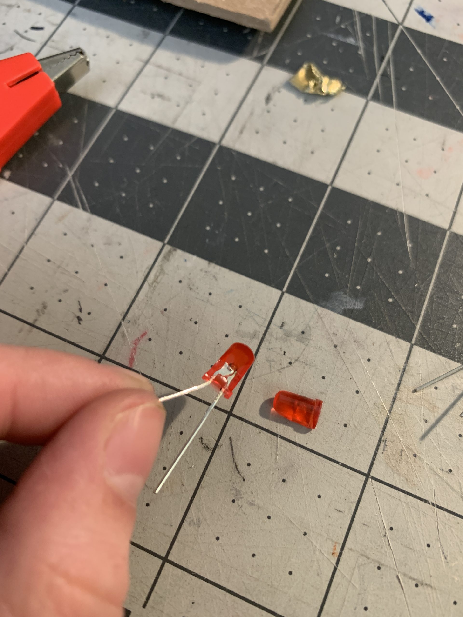
While this issue was frustrating and strange, it did allow us to use a stepper motor that was far more robust than the one we were using before. This helped with the construction of our circuit since we did not have to worry that the arm would not move quick enough. however oh, I believe the use of outside power source led to the following image – Jubbies accidentally blew up an LED while accidentally connecting the power and ground of the LED without the graphite circuit in-between. This was a good lesson, as it reminded her to be very conscientous of these wires not connecting again.
Another strange issue that was not ideal but did not hinder the intended mechanism was an ever present jitter in the stepper motor arm. This jitter was likely due to analog interference and could be resolved in the future with a threshold or other tool to smooth the data recieved by the potentiomenter. I had considered using a rotary encoder mid-project over the potentiometer as I heard that it was less susceptible to analog interference, but I was unable to quickly implement this and ended up just using the potentiometer.
Bonus: I strapped a pen onto the stepper motor arm and found this jitter made for an interesting drawing tool to be explored further in the future – Jubbies
Carlos’s progress
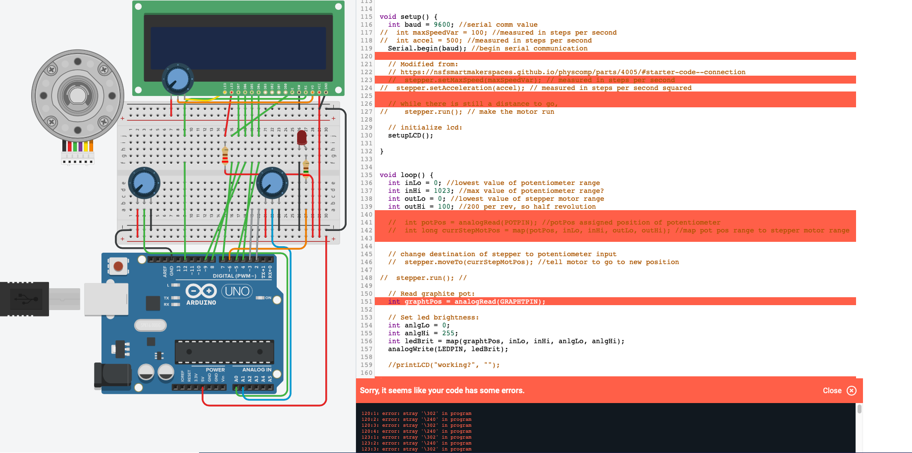
My (Carlos’s) Tinkercad code somehow became ridden with invisible special characters \302 and \240, maybe after copying and pasting the code from iMessage. They were nearly impossible to remove without retyping those lines word for word all over again. Because of this, the code wouldn’t compile, and I couldn’t check if the rest of the code was correct.
Tinkercad does not have a stepper motor, so I used the larger, grey DC Motor with Encoder as a mere placeholder, not even connected to anything.
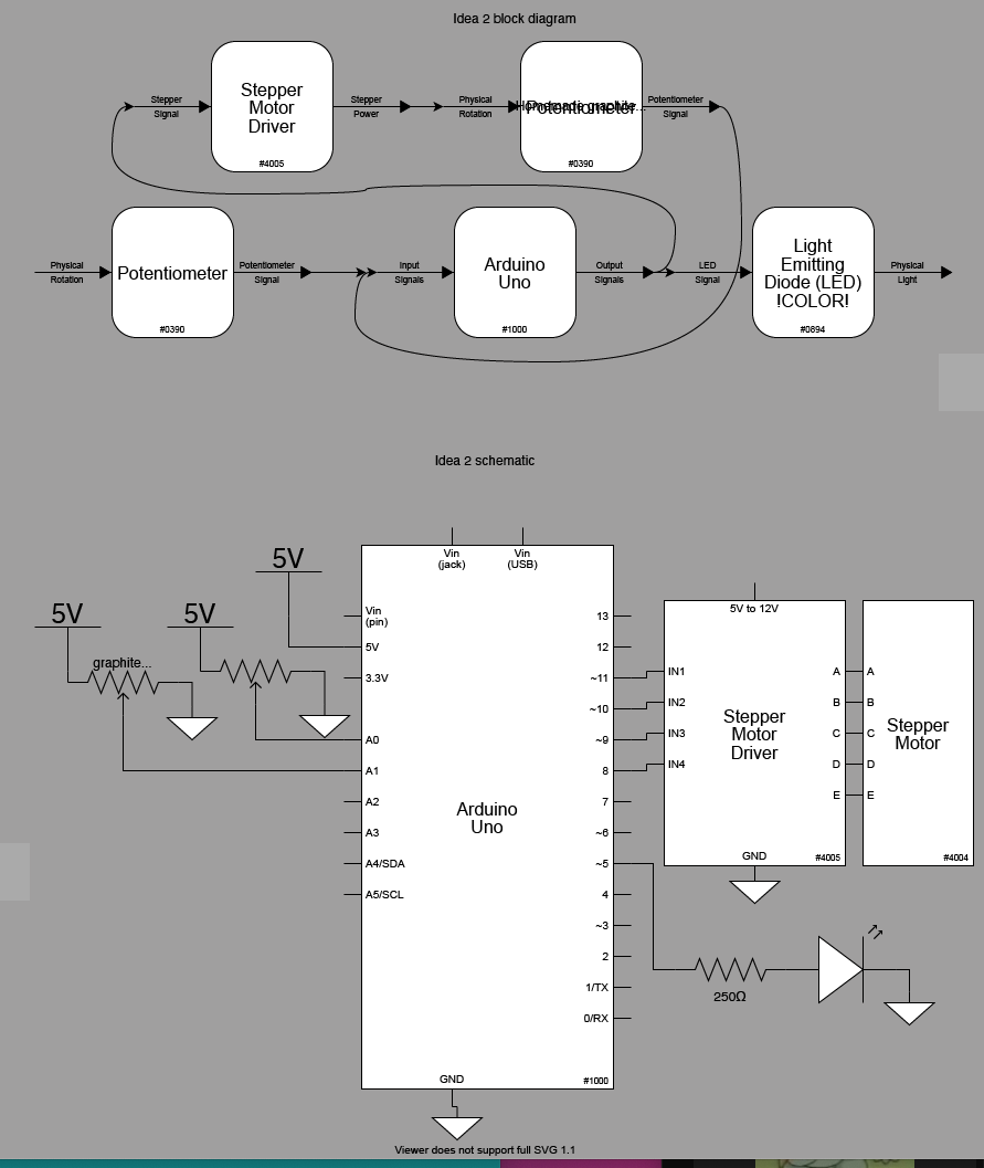
Block Diagram & Schematic:
/*
  60-223, Double Transducer: The Convoluted Potentiometer
  Jubbies Steinweh-Adler
  Carlos Ortega

  Collaboration and sources:
  1) I collaborated with Carlos to figure out the order of the code
  2) Referenced heavily Circuit Digest stepper motor with Potentiometer
  https://circuitdigest.com/microcontroller-projects/stepper-motor-control-with-potentiometer-arduino
  3) The maker cards really helped me understand the parts
  https://nsfsmartmakerspaces.github.io/physcomp/parts/4005/#starter-code--connection
  4) I referenced Household Hacker's youtube video about paper and graphite
  circuits to get started with this idea.

  5) Tate gave me some advice on how to use the LCD display since I could
  not figure it out.

  Challenge(s): Remote collaboration was difficult, as was
  working through unknown bugs with the Stepper Motor. The
  stepper motor and driver did not work and simply had to be
  replaced. Additionally, I could not get the LCD working in
  time.

  Next time: It was extremely helpful to segment the process
  of solving this code, proving that each mechanism works
  independently of the whole rig. I will certainly do this again
  as it really sped things up and made them less stressful.
  In terms of issues, I think I should have given more time
  to the physical assembly of all the parts, since this took
  way longer than I thought. I spent a lot of time trying to
  fashion non-destructive mounts. It was hard to physically arrange
  the parts together in a semi-elegant way. I also want to give
  more time to the small final details, like resolving the
  stepper motor jitter.

  Another thing I want to take forward from this project was using
  a clearly understood visual indicator of the process like the
  graphite semicircle, since I found this helped people make sense
  of this project quickly.

  Description:

  Pin mapping:

  Arduino pin | type       | description
  ------------|------------|-------------
  A0            Input       Potentiometer input
  12            LCD Pin     Used for the LiquidCrystal Library
  11            LCD Pin     Used for the LiquidCrystal Library

  2             Input       Stepper Motor driver
  3             Input       Stepper motor driver, direction

   7            LCD Pin     used for the LCD
   6            LCD Pin     used for the LCD
   5            LCD Pin     used for the LCD
   4            LCD Pin     used for the LCD


*/
//Initialize the LCD
#include <LiquidCrystal.h> //include the LCD library code


// initialize the library by associating any needed LCD interface pin
// with the arduino pin number it is connected to
const int rs = 12, en = 11, d4 = 7, d5 = 6, d6 = 5, d7 = 4;
LiquidCrystal lcd(rs, en, d4, d5, d6, d7);


//Initialize the Stepper

#include <AccelStepper.h> // including the accelstepper library for more control of motor


const int POTPIN = A0; //potentiometer input pin

const int STEP_PIN = 2; // A4988 "STEP" pin wired to Arduino pin 2 (you can change this)
const int DIR_PIN = 3; // A4988 "DIRECTION" pin wired to Arduino pin 3 (you can change this)

int pos = 100; // variable to store motor position instruction, 100 is half rotation

// Modified from:
//https://courses.ideate.cmu.edu/60-223/s2021/tutorials/stepper

AccelStepper stepper(1, STEP_PIN, DIR_PIN);

// Will compare this to currStepMotPos later, inside loop.
int prevStepMotPos = 0;

unsigned long timerVar = 0;
const int WAIT = 200; //does not change

int LCDupdate = 0;

void setup() {
  int BAUD = 9600; //serial comm value
  int maxSpeedVar = 100; //measured in steps per second
  int accel = 500; //measured in steps per second
  Serial.begin(BAUD); //begin serial communication

  //---LCD Setup---
  lcd.begin(16, 2);

  // Modified from:
  // https://nsfsmartmakerspaces.github.io/physcomp/parts/4005/#starter-code--connection

  //---Stepper Motor setup---

  stepper.setMaxSpeed(maxSpeedVar);    // measured in steps per second
  stepper.setAcceleration(accel); // measured in steps per second squared

  // while there is still a distance to go,
  stepper.run(); // make the motor run


}


void loop() {
  unsigned long currentTime = millis();
  unsigned long previousTime = 0;


  }

  int inLo = 0; //lowest value of potentiometer range
  int inHi = 1023; //max value of potentiometer range
  int outLo = 0; //lowest value of stepper motor range
  int outHi = 100; //200 per rev, so half revolution


  int potPos = analogRead(POTPIN); //potPos assigned position of potentiometer

  //map pot pos range to stepper motor range
  int long currStepMotPos = map(potPos, inHi, inLo, outLo, outHi);


  //Change destination of stepper to potentiometer input
  stepper.moveTo(currStepMotPos); //tell motor to go to new position

  prevStepMotPos = currStepMotPos; //save current value into previous value
  stepper.run();

  //Serial.println(prevStepMotPos); //for debugging

  LCDPotVal =
  LCDStepperVal =

//LCD Update
  /*if (currentTime - timerVar >= WAIT) {
    lcd.clear();
    lcd.home();
    lcd.print("i:");
    lcd.print(LCDPotVal0;
    lcd.setCursor(6, 0);
    lcd.print("m:");
   */
    previousTime = currentTime;


}
Discussion:
This project was an exciting introduction to many new concepts such as assembling separate components into one operation, using graphite as a resistor, learning how to debug in context, soldering, and collaborating remotely. Since we were both excited about this idea, it was easier to push through these bugs. Learning hands-on was a great experience , since somebody can tell you what it’s like to explode an LED, but before you actually do it, I would argue that it is far less likely to sticks with you.
The biggest barriers we faced had to do with significant bugs and remote collaboration. The stepper motor/ stepper motor driver bug , although circumnavigated, was never resolved. Only with the help of our professors are we able to move on from that point through replacing our parts.
Additionally, since Carlos is studying remotely and never received his Arduino kit from customs, there was simply not an option to collaborate on the hardware issues. Since the software and hardware are delicately intertwined, this also made it extremely difficult to collaboratively resolve software issues as well. While on paper, tinkercad seems to be a good option to ease this situation, the lack of a stepper motor, stepper motor driver, and graphite resistor on the platform, as well as the inability to import libraries, made this tool unhelpful.
That being said, we were able to have rewarding discussions about conceptual development and enjoyed the process of translating our idea to a real tangible thing.