By: Vishnu Raghavan
After a time limit is exceeded, two Servo motors push your computer screen closed, signaling time for a break.
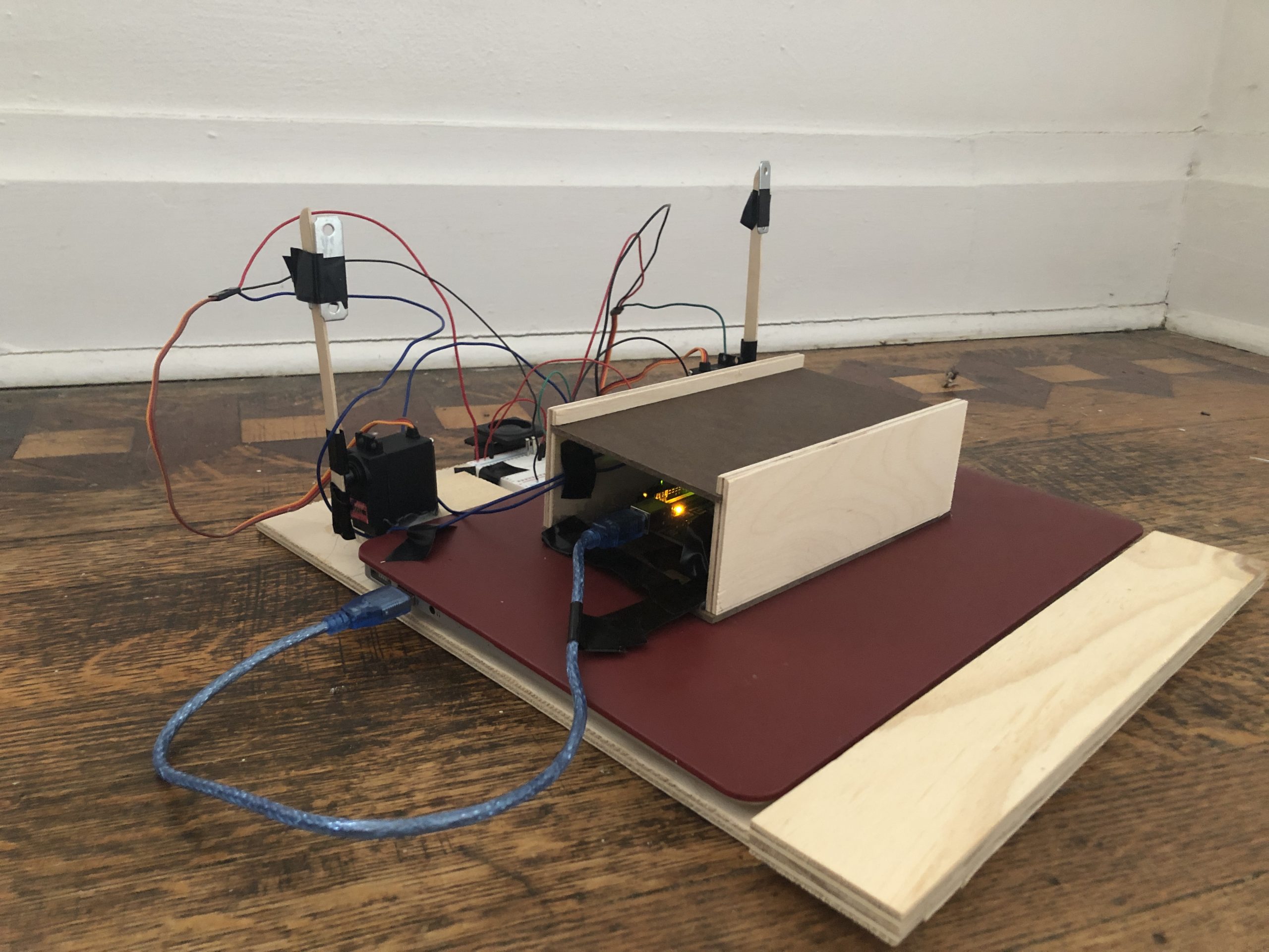
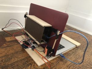
Demo:
Ideation:
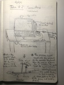
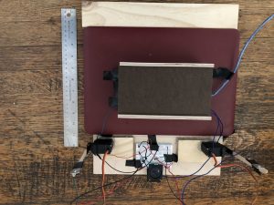
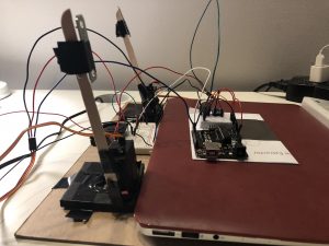
Photo for Scale:
Servo Motor:
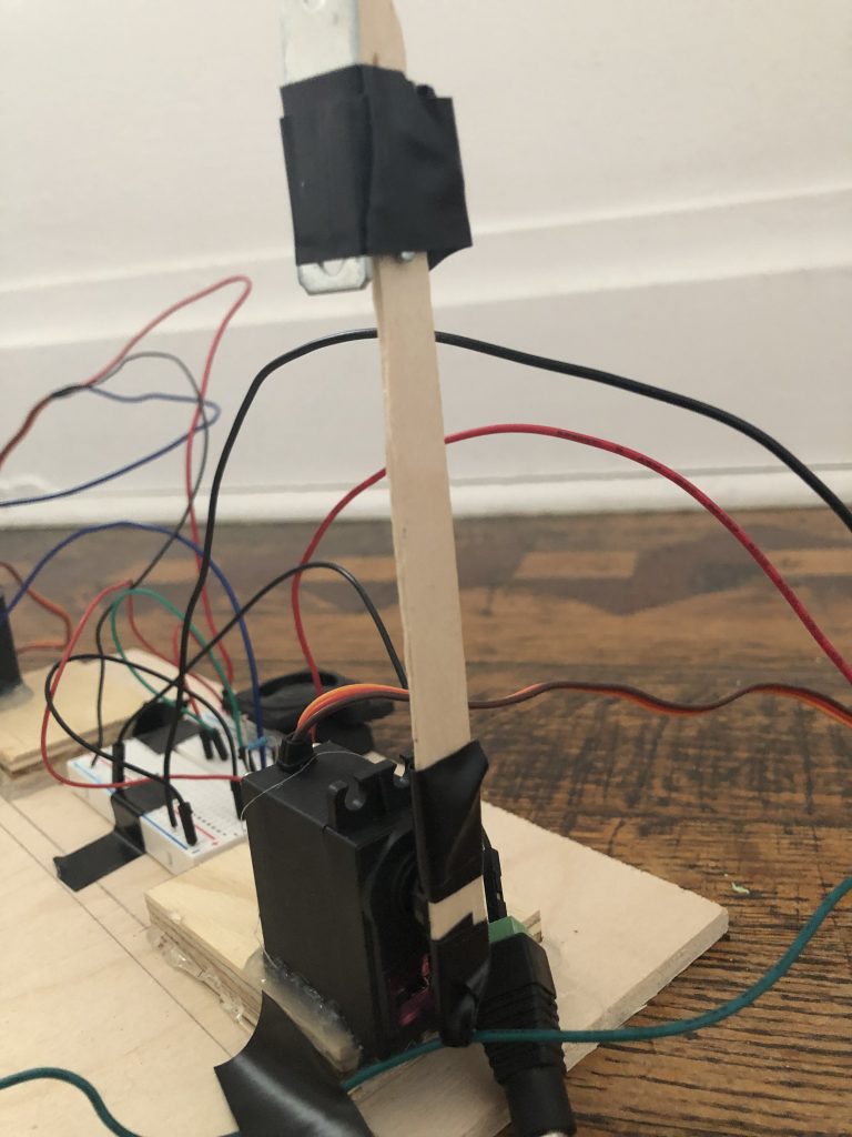
Servo motor (1/2) that pushes the computer screen down when the screentime limit is exceeded
Arduino Control Center:
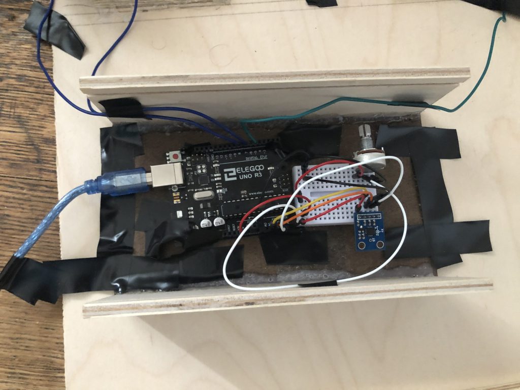
Main “control center” of device. Contains Arduino, as well as breadboard with accelerometer (for sensing “open” vs “closed” orientation of screen) and potentiometer (for adjusting screentime limit).
Decision Points:
- Decided to use accelerometer instead of pressure sensor:
2. Decided to create a wood-based platform/environment for project, along with a wood box to enclose Arduino:
I decided to make a platform containing all the parts of the project; after building a mockup, I realized I could apply my woodworking skills to craft an aesthetically-pleasing base for the final project.
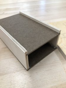
To keep the project aesthetically clean, I did not want the Arduino and other wiring to be visible. I eventually decided to make a sliding lid, which would allow me to reach in and fiddle with the electronics if need be.
Discussion:
While I was very satisfied and thankful I was able to get the meat of my project working, there were certain features or glitches which I believe could be improved or fixed for a future iteration. Based on a classmate’s feedback, one improvement concerns how the Arduino is placed: “The box seems a little bulky to attach on the back of your computer, so maybe there’s a nicer way to hold the Arduino.” In the original project, I enclosed the arduino inside a wooden box with a sliding top, for ease of access. I then mounted the box on the back of the computer screen, taping it to hold it together (avoiding glue, as that would damage the computer case). However, based on the feedback, I can actually move the box off of the computer. To accomplish this, I will need to allocated a larger plaftform to accomodate the box, its wiring, and the servo motors, and the speaker pad. Additionally, a major reason I mounted the box on the computer was because the Arduino’s upload cable had to connect to the Mac’s USB port. In the future, I will invest in a special adaptor or extender that will allow me to connect to the computer without keeping the Arduino in close proximity.
Although I did attempt to add an aesthetic tone to the project, there were certain aspects about it which were still “exposed”. Most notably, much of the wiring I used was visible, especially on the breadboard which contained the speaker. As one classmate recommended, “Possibly a next step could be a phone mount onto your screen. That way you wouldn’t need any extra cables, and you could use a graphical user interface to set the screentime.” Not only would this clean up any exposed (and confusing) wiring I may have, it will add an extra layer of robust complexity to my project. Not only would I be challenged in finding a way to digitize my interface, I would also need to make the design user-friendly. I would focus on optimizing my project on a hardware, software, and user-centric level.
In spite of the end result, the workflow was bumpy. During the process, I was nervous that my accelerometer would not be very sensitive to the change in position to the computer screen, and therefore not be able to send a meaningful signal to the servo motors. In fact this was initially a problem, as my accelerometer was not outputting logical values based on position. I soon realized that, since I was reusing an accelerometer from the previous project, the solder used must have fried the board. After switching to a fresh piece, it worked fine.
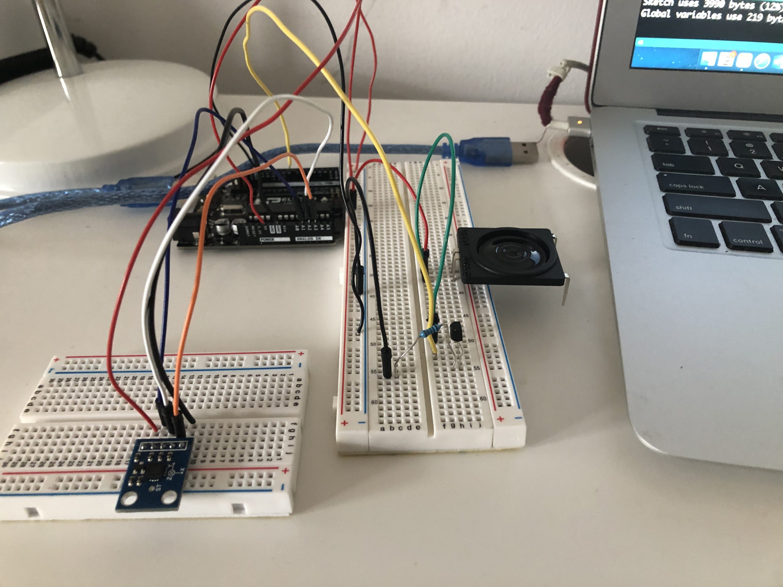
One major source of annoyance, and a general failure of my project, was the speaker, which would ideally beep when my screentime limit was almost exceeded. In this way, the speaker would act as a “warning”, allowing me to save any work before the motors would slam the computer shut. I played around with the “debouncing” framework in the early stages (the speaker was originally button-controlled) but eventually sought to employ a simpler “delay” framework. I did have to keep track of the current and previous states, but I would get mixed results. Sometimes, the speaker would blare correctly, but after a few iterations of opening and closing, would stop emitting completely. Given the time crunch, I decided to move on from this problem, in order to devote more time to the aesthetic aspects of the project.
Another idea that I had, but which never came to fruition, was to create an LCD display that would output the total amount of screentime, as well as the time left. However, given both the time crunch, as well as the revelation that I could not maneuver a large amount of wiring at that point in the project, I ended up scrapping the idea. Nonetheless, this is an idea that would be good for a future iteration.
Overall, I was proud of how my project turned out. I am especially proud of how I incorporated my woodworking experience into the project, given that I had taken the woodworking mini just this semester. I was relieved to be able to get the servo motors working reliably, along with the sliding box top I had built in the woodshop. Looking ahead, I would like to try to digitize much of the controls, perhaps through a touch-screen GUI and some Wifi-enabled connection. This will challenge me to broaden my expertise beyond simple electronics, to the world of cloud software and computing.
Technical information:
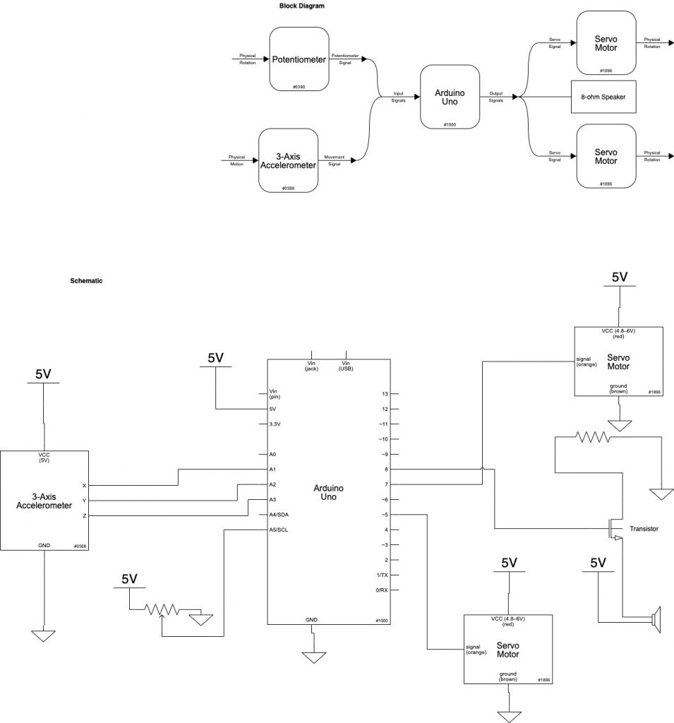
Block diagram/Schematic:
Code:
/*60-223 Project 2: Screentime Watchman
 * Vishnu Raghavan (vishnur)
 * April 8th, 2021
 *
 * Description: This code measures the orientation of the laptop screen via an accelerometer.
 * Once the laptop reaches 90 degrees upright, a timer starts (determined by the current potentiometer setting).
 * When the timer nears a certain limit, the speaker goes off, and soon afterwards,
 * the Servo motors swing by a certain (predetermined) angle.
 *
 * Pin mapping:
 *
 * Arduino Pin | Type | Description
 * ------------|------|------------
 * 5            output  Right servo
 * 7            output  Left servo
 * 8            output  8-ohm speaker
 * A1           input   X-input to accelerometer
 * A2           input   Y-input to accelerometer
 * A3           input   Z-input to accelerometer
 * A5           input   Potentiometer to control screentime
 *
 * Code bits:
 * -Accelerometer code taken partially from maker cards website
 * -Servo setup taken from Servo example in class
 */


#include <Servo.h>

const int accelXPin = A1; // Analog input pin for X movement
const int accelYPin = A2; // Analog input pin for Y movement
const int accelZPin = A3; // Analog input pin for Z movement

const int SPEAKERPIN = 8;
const int POTPIN = A5;

Servo motor1;
Servo motor2;

const int MOTORPIN1 = 5;
const int MOTORPIN2 = 7;

//Servos in "down" position
const int INIT_ANGLE1 = 65;
const int INIT_ANGLE2 = 160;

//Servos in "up" position
const int FINAL_ANGLE1 = 160;
const int FINAL_ANGLE2 = 65;


// Variables to keep track of the current positions
int accelXPos = 0;
int accelYPos = 0;
int accelZPos = 0;

//Timer, and flags to keep track of current and prev state of screen
int timer = 0;
bool prevUp = LOW;
bool currUp = LOW;

unsigned int screenTime;


void setup() {

  motor1.attach(MOTORPIN1);
  motor2.attach(MOTORPIN2);

  pinMode(accelXPin, INPUT);
  pinMode(accelYPin, INPUT);
  pinMode(accelZPin, INPUT);

  pinMode(SPEAKERPIN, OUTPUT);
  pinMode(POTPIN, INPUT);

  motor1.write(INIT_ANGLE1);
  motor2.write(INIT_ANGLE2);

  Serial.begin(9600);


}

void loop() {
  //Get accelerometer orientation (specifically, height)
  accelZPos = analogRead(accelZPin);

  int screenTimeTmp = analogRead(POTPIN);
  screenTime = map(screenTimeTmp, 0, 1023, 3000, 8000); //Better range for screentime
  delay(1000);

  //Screen down
  if (390 <= accelZPos and accelZPos <= 405) {
    motor1.write(INIT_ANGLE1);
    motor2.write(INIT_ANGLE2);
    timer = 0; //Timer off
    currUp = LOW;

    noTone(SPEAKERPIN);
  }


  //Screen just flipped up
  if (accelZPos >= 320 and accelZPos <= 340 and prevUp == LOW) {
    timer = millis();
    currUp = HIGH;
  }

  //If screen up for 4 seconds, warning speaker for 2s
  if (accelZPos >= 320 and accelZPos <= 340 and
      prevUp == HIGH and millis() - timer >= (screenTime - 3000) and millis() - timer <= (screenTime - 1000))
  {
    tone(SPEAKERPIN, 500);
  }

  //After 6 seconds total (2s after warning), flip screen down
  if (accelZPos >= 320 and accelZPos <= 340 and prevUp == HIGH and millis() - timer >= screenTime) {
    motor1.write(FINAL_ANGLE1);
    motor2.write(FINAL_ANGLE2);


    currUp = LOW;
    timer = millis(); //Reset timer
    noTone(SPEAKERPIN);
  }

  //Update prev state of screen
  prevUp = currUp;


}