
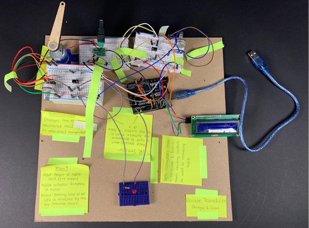
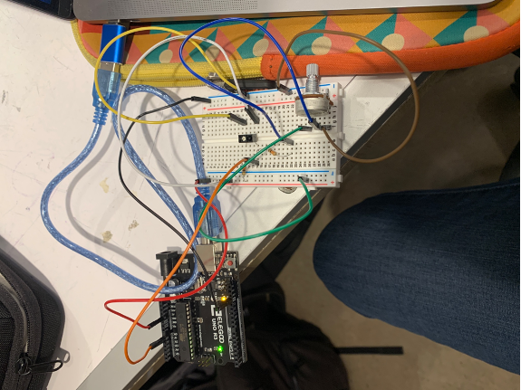
Overall photo for proportion and scale
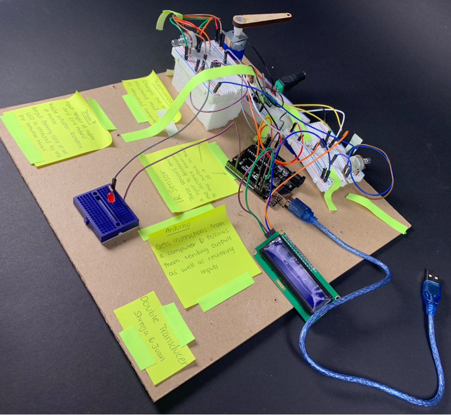
Overall photo for proportion and scale (alternate angle)
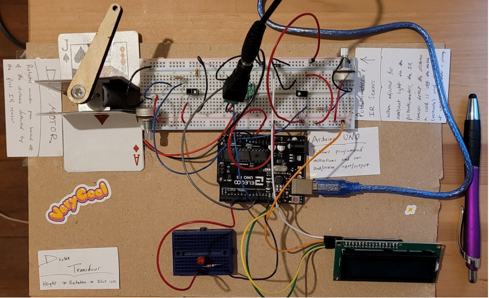
Overall photo of version_juan for proportion and scale, with a pen as reference for size
Close-ups
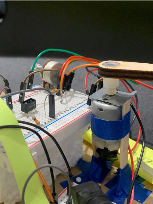
Here is a closeup of the motor setup. Here you can see how both the motor and the IR sensor are elevated and the propellor is attached to the tip of the motor, allowing it to spin over the top of the sensor.
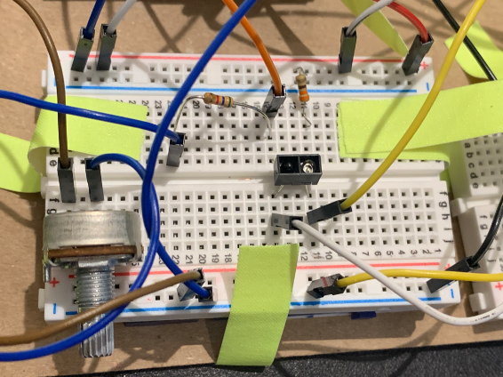
Here is our first IR sensor which is used to get the height of the index card off of the table. It was necessary to hold down the wires to the side to ensure minimal interference with the sensor’s readings.
Narrative description
For our double transducer, we were tasked with converting the height of an index card, ranging from 1 to 4 inches, to the blinking rate of an LED. When considering how to gauge the height of the index card, we started looking at the different proximity sensors that would be useful in this situation. After consulting with both Zach and Eric, we determined that the best one to use would be the IR sensor, which emits a light and then receives it after it bounces off a nearby surface. With this, one challenge that we faced was adjusting the potentiometer attached for ambient light, which changed constantly even in the classroom. For our second component, we decided that an interesting conversion to explore would be the rotational speed of a motor. We decided to use a DC motor, and then another IR sensor to detect the number of rotations that occurred within a given time period. This was gauged by marking the number of times an attached wooden piece went over the IR sensor per second. Finally, we converted this to the rate at which an LED blinked. At the request of the group after us, we maintained that every time the LED turned on, it would only stay on for 25 milliseconds. Because of this, we were actually manipulating the time between blinks as opposed to the time the LED was on. This range was constructed to stay between about 1-20 blinks per second.
Progress images
Here is an image of what we had as we were initially figuring out the IR sensor and how to hook it up to the Arduino.
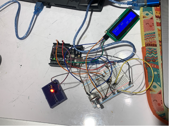
Here we have our proximity sensor, LCD display, and LED hooked up to the arduino, making sure that each part is able to run properly without the motor component.
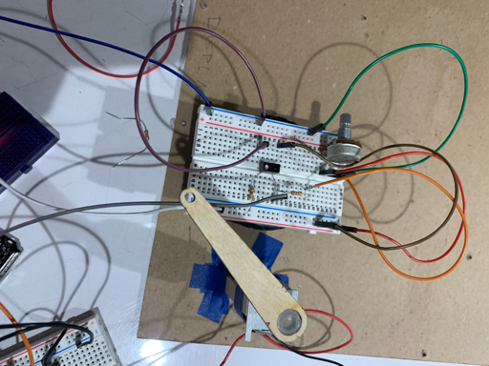
This is the setup we used to trigger our second IR sensor, which detected the change in rotation of the motor. The wooden piece attached to the top was essential to allowing the IR sensor to count the rotations for rps.
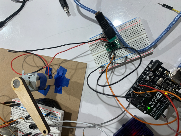
Here is the initial setup for our motor, where we propped it up on popsicle sticks to make it so the propeller overhead was at a good height for the reader.
Discussion
The path to creating our double transducer was by no means a simple and smooth one. Unsurprisingly, there were a few hurdles in creating our double transducer which both challenged and strengthened our problem-solving and researching abilities. Of the 10 components used in our project, nearly half were components we were already experienced in from previously assigned online course modules. We knew how to work with the Arduino UNO controller, potentiometers (of which we needed 2), as well as our final output: an LED light. Ultimately, that meant that we needed to familiarize ourselves with 5 new components: an LCD screen, an IR sensor (of which we’d use two), an H-Bridge motor driver, a DC barrel jack adapter, and a DC motor. For the sake of time, we decided to assign ourselves each half of the total new components to work on. Shreeja was responsible for the two IR sensors and LCD screen, and Juan was responsible for the H-Bridge motor driver, DC barrel jack adapter, and the DC motor itself.
Setting up and utilizing the parts we were already familiar with (the LED, Arduino, and potentiometers) was relatively trivial. It was only until we began experimenting with the new components that the difficulty of the project increased. Each new component took some time to get used to, and although some required more time than others, there were a few components that stuck out more in terms of giving us the most difficulty. The two components that come to mind are the IR sensors and the H-Bridge motor driver. The H-Bridge motor driver was a fairly non-trivial component since it essentially served as a mini-arduino for the DC motor in the sense that it read input and gave output that was directly tied to the DC motor. The H-Bridge required some soldering in addition to research in order to ensure that it would work with the DC barrel jack adapter and DC motor. The IR sensors, on the other hand, were deceptively difficult; we were technically able to get them functioning early on, but we were constantly having difficulty adjusting the sensor’s sensitivity to our liking. Factors such as ambient lighting (which the potentiometers helped us control), possibly faulty sensors, and confusion with the software aspect of IR sensor input and output led to a majority of our time being spent on fine-tuning the IR sensors to work like we wanted them to. They were, after all, crucial to our transducer as not only was it how our final project received input, it was also the means in which we were able to measure the speed of our motor. Given their importance, the long period of time we spent trying to perfect our IR sensor settings was in retrospect justified.
I can’t help but wonder what would’ve happened if we had decided to use an ultrasonic ranger instead of our IR sensors to detect distance. We had initially chosen to use IR sensors because we felt that it was more straightforward and natural, but in theory we could have also used an ultrasonic sensor to at the very least detect the height of an index card, and maybe even to detect the rotations our DC motor is spitting out. It’s possible that such a substitution could have dramatically reduced the time we spent on the project since we wouldn’t have to constantly adjust our IR sensors, but it’s also probable that we would have run into some other roadblock instead.
Overall, the project itself was enjoyable and more importantly quite educational. We were able to learn how to use certain components like LCD screens, DC motors, and IR sensors, decently well enough to the point where we could use them in future projects with much more comfort. If this project is any indication on how future projects will be for the course, then we’re very much looking forward to progressing through the course and learning even more components and arduino-related material.
Functional block diagram and schematic
Functional block diagram
Schematic
//Double Transducer: from height to light
//
//By Team 7
//
// For the code, in addition to establishing each of the pins used
// as inputs or outputs in the arguino, we also did most of our mapping
// conversions with the code. Also, we used the code to time each of the
// parameters and display the values on our LCD.
//
//
// Each of the pins are commented below to explain their function:

// shortcut to refer to the IR sensor pin
const int PROXPIN = A0;
//shortcut to refer to LED pin
const int LEDPIN = 4;
//shortcut to refer to motor pin
const int MOTORPIN = 10;
//shortcut to refer to the IR that reads the motor val
const int PROXMOTOR = A1;

int motorProxPrevious = 0;
int rotations = 0;
int rps = 0;
int lastCycle = 0;
unsigned long timer = 0;
const int INTERVAL = 1000; //number of milliseconds per second for reading

unsigned long lastTime = millis();
unsigned long LEDwait = millis();
unsigned long LEDon = millis();

// imports the LCD programming library
// and initializes the screen with it's dimensions
#include <Wire.h>
#include <LiquidCrystal_I2C.h>
LiquidCrystal_I2C screen(0x27, 16, 2);

byte frowny[] = {
  B00000,
  B11011,
  B11011,
  B00000,
  B00000,
  B01110,
  B10001,
  B00000
};

void setup() {
  //initializes the input IR sensor to get the proximity of the index card
  pinMode(PROXPIN, INPUT);
  Serial.begin(9600);

  pinMode(MOTORPIN, OUTPUT);
  Serial.begin(9600);

  pinMode(LEDPIN, OUTPUT);
  digitalWrite(LEDPIN, LOW);

  pinMode(PROXMOTOR, INPUT);
  Serial.begin(9600);

  //initializes the LCD screen and turns on backlight, sets cursor home
  screen.init();
  screen.backlight();
  screen.home();
}

void loop() {
  int readVal;
  readVal = analogRead(PROXPIN);

  //to find difference in distance between them
  int motorProx;
  motorProx = analogRead(PROXMOTOR);
  Serial.println(motorProx);

  //translates the index card height to the speed of the motor
  int motorSpeed = map(readVal, 10, 90, 50, 70);
  analogWrite(MOTORPIN, motorSpeed);

  //measure motor fan rotational speed
  int difference = 0;
  //change in diff
  if (motorProx != 0){
    difference = motorProx - motorProxPrevious;
  }

  //when piece is detected, increment rotations (one complete rotation)
  if (difference >=2){
      rotations++;
  }

  motorProxPrevious = motorProx;


  if (millis() >= timer){
    rps = rotations;
    rotations = 0;
    timer = millis() + INTERVAL;
  }

  int blinkGap = map(rps, 0, 10, 25, 925);

  digitalWrite(LEDPIN, LOW);
  delay(blinkGap);
  digitalWrite(LEDPIN, HIGH);
  delay(25);

  //screen display code
  screen.print("i:");
  screen.print(readVal); //shows the IR value
  screen.print("  ");
  screen.print("m: ");
  screen.print(motorSpeed);
  screen.setCursor(0, 1);
  screen.print("       ");
  screen.print(rps);
  screen.print("  o: ");
  screen.print(blinkGap);
  screen.home();
}
Project done by Shreeja and Juan