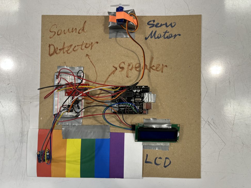
Photos that show scale:
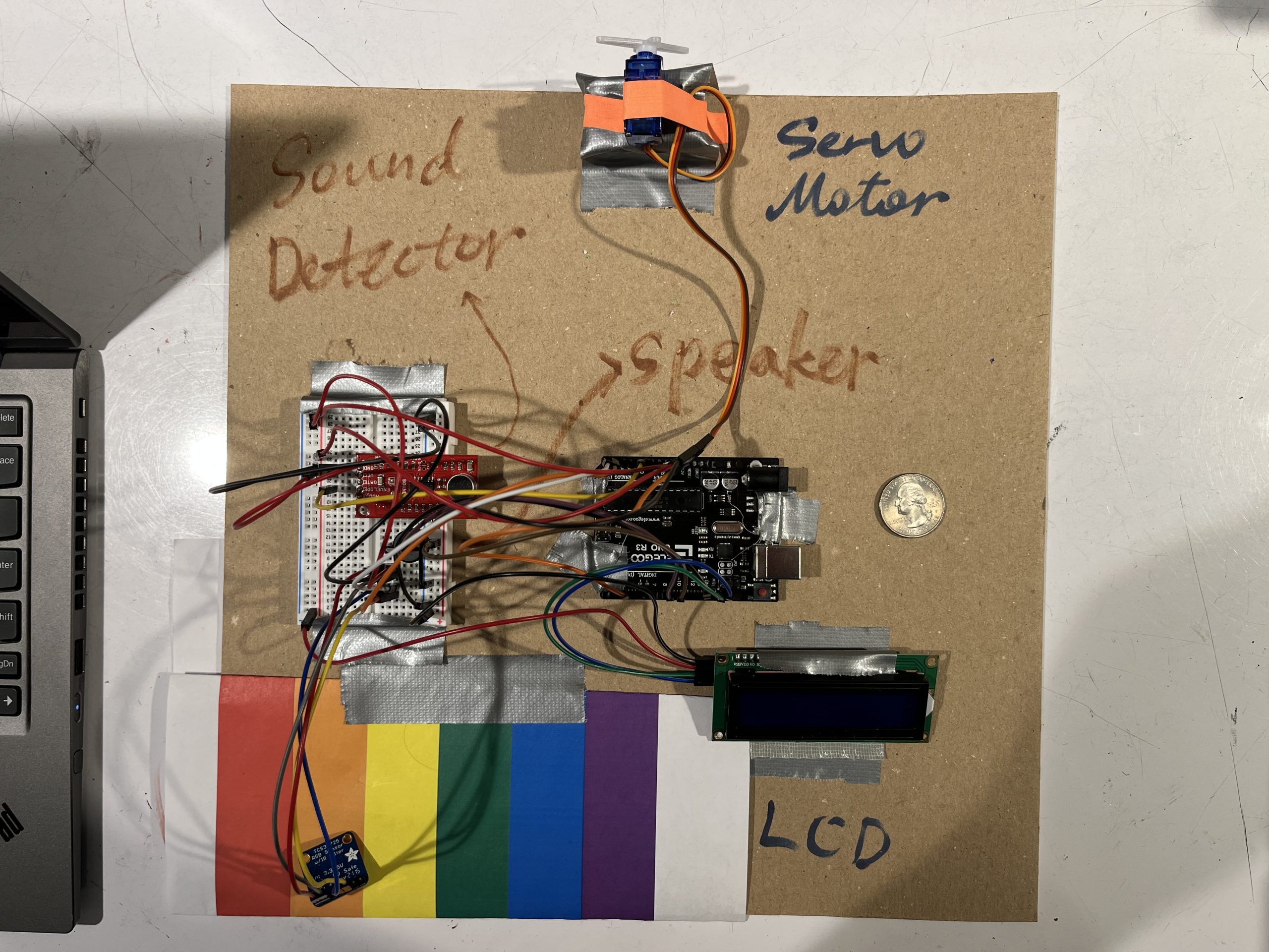
Zoey’s scale compared to a quarter dollar
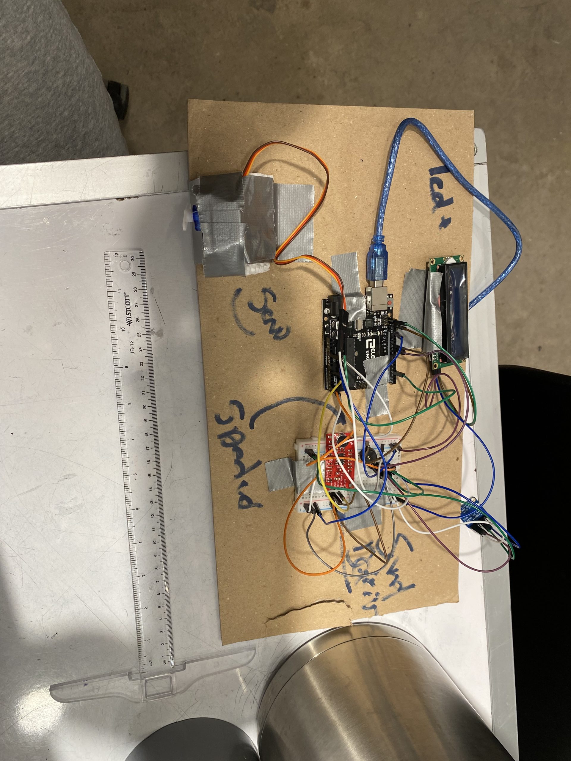
Jerry ‘s scale for a ruler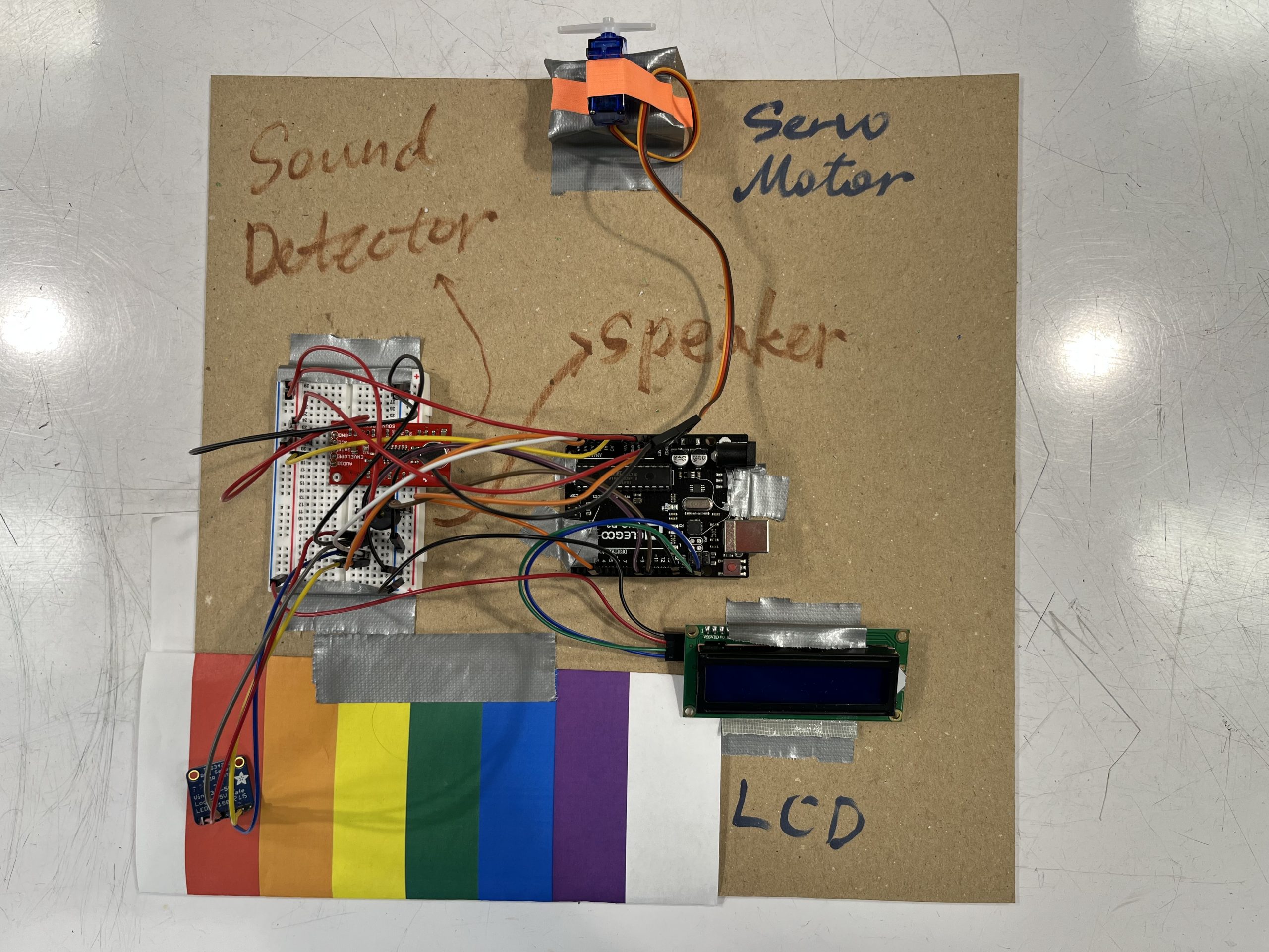
Videos:
Progress images:
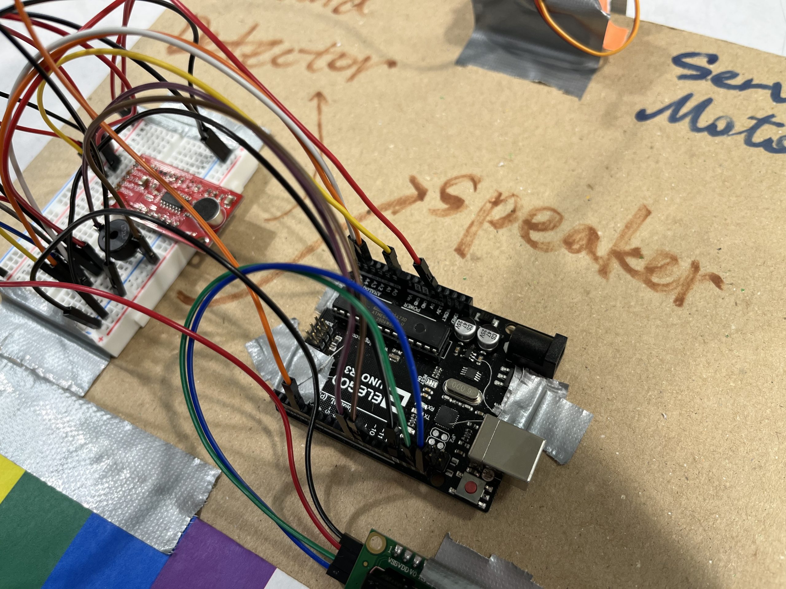
A closer view to the speaker
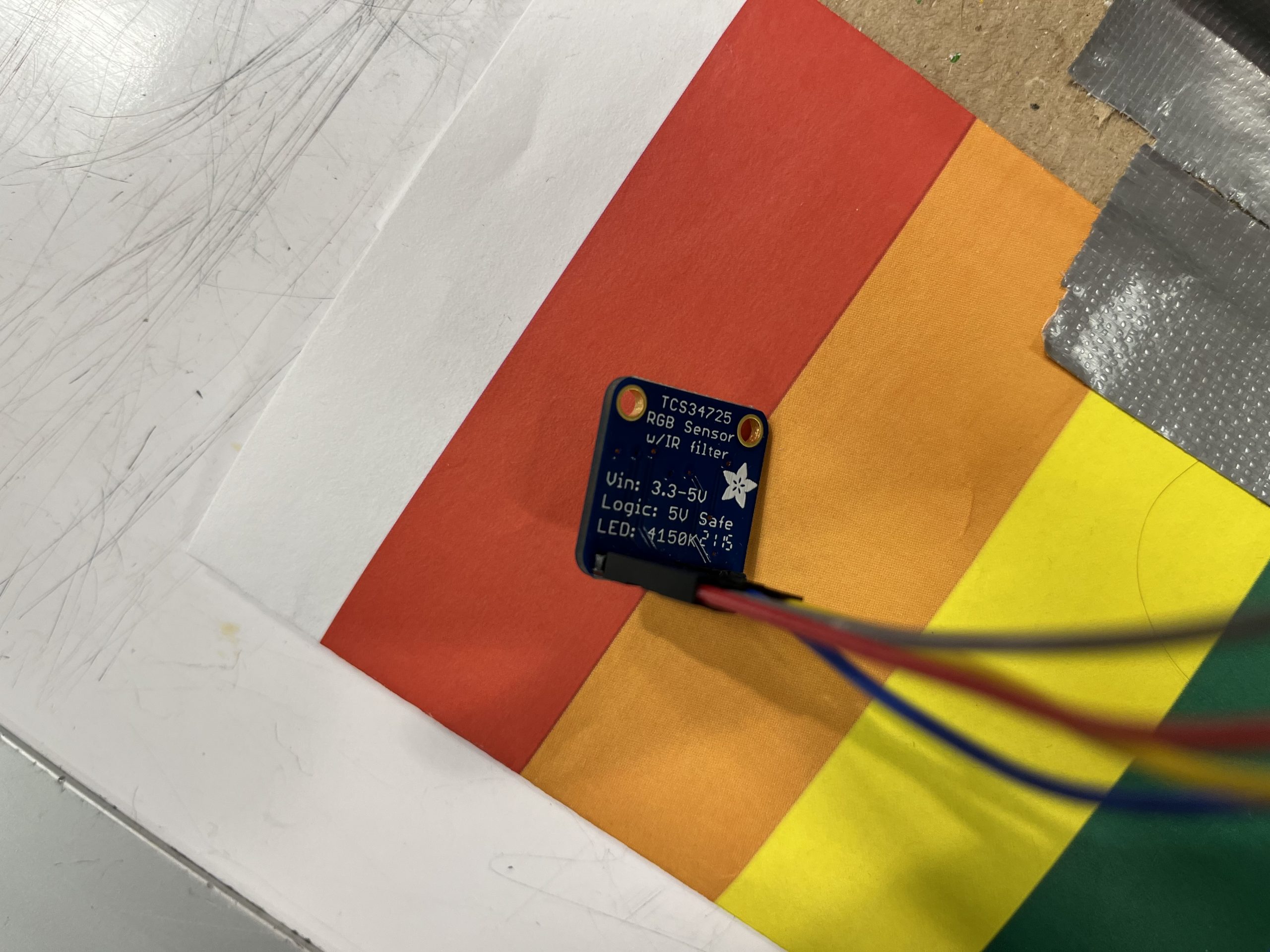
The color sensor is not fixed so we can move it to whatever color we want to detect
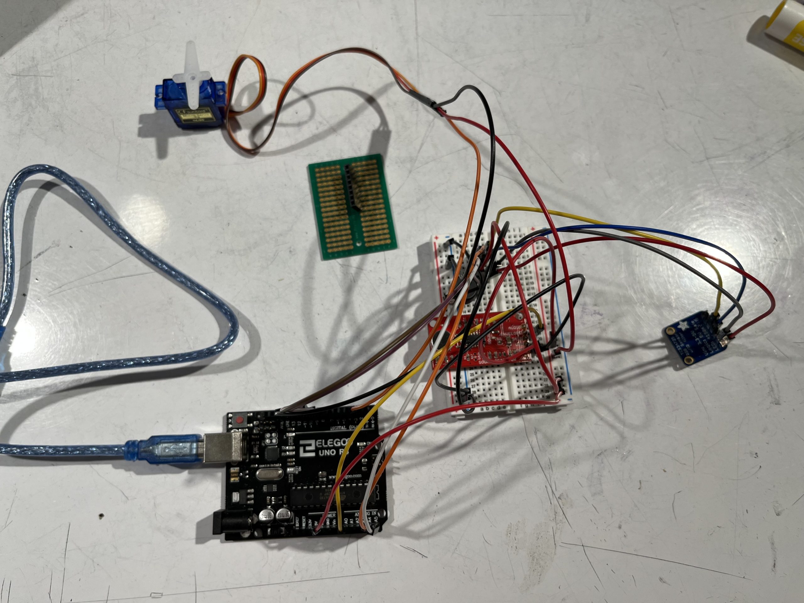
Wiring process
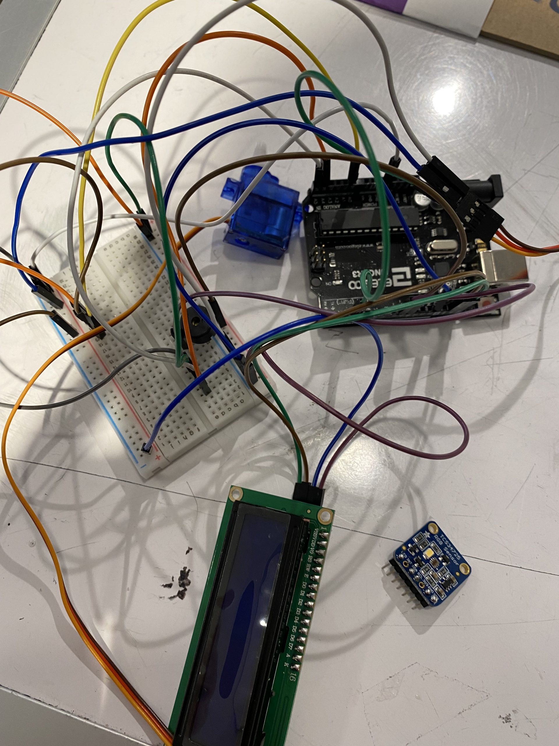
Wiring before the RGB sensor was put in
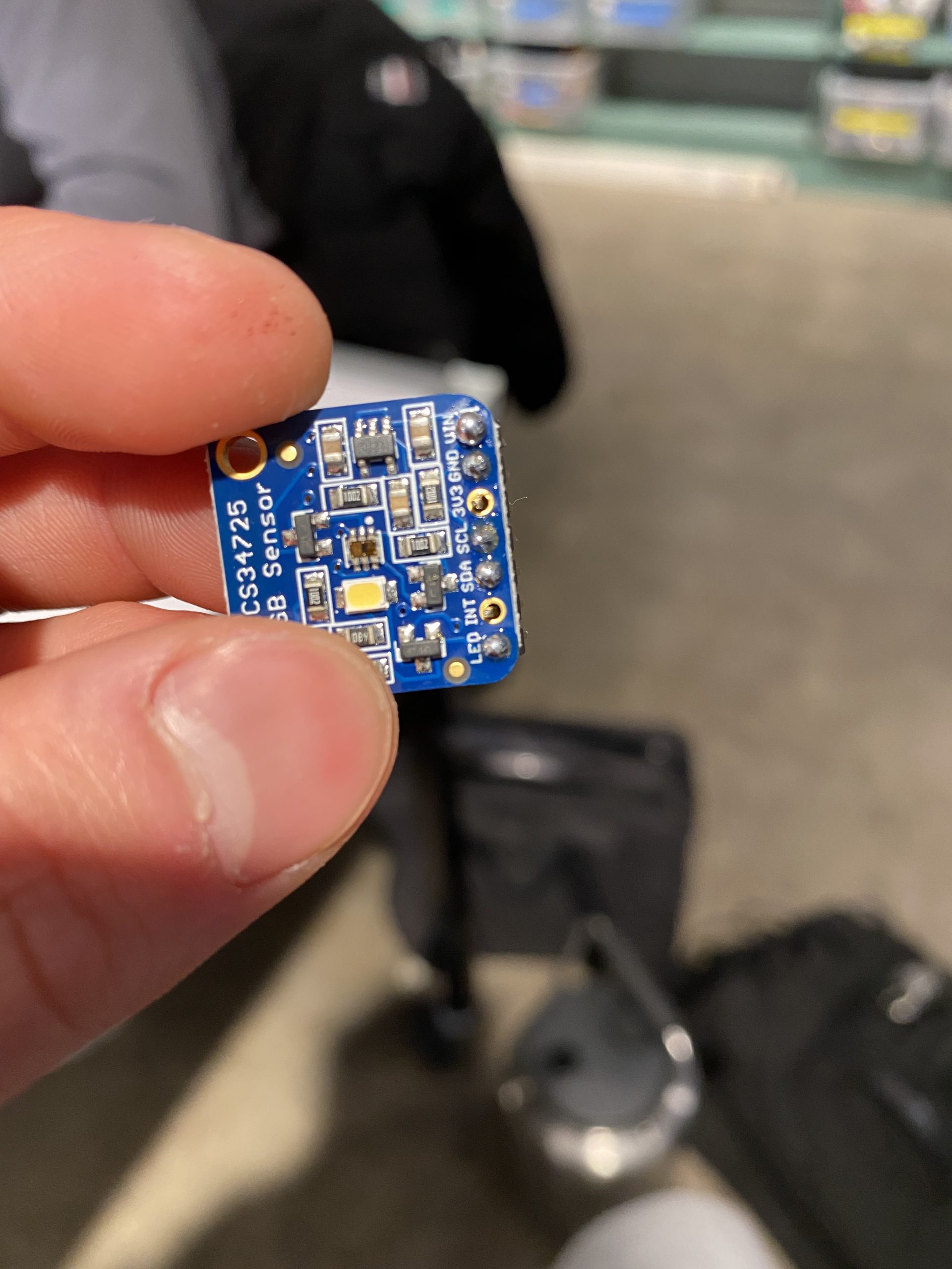
Here is the soldered RGB sensor! This is the first time soldering for both of us, and it was very fun!
Simple Narrative Description
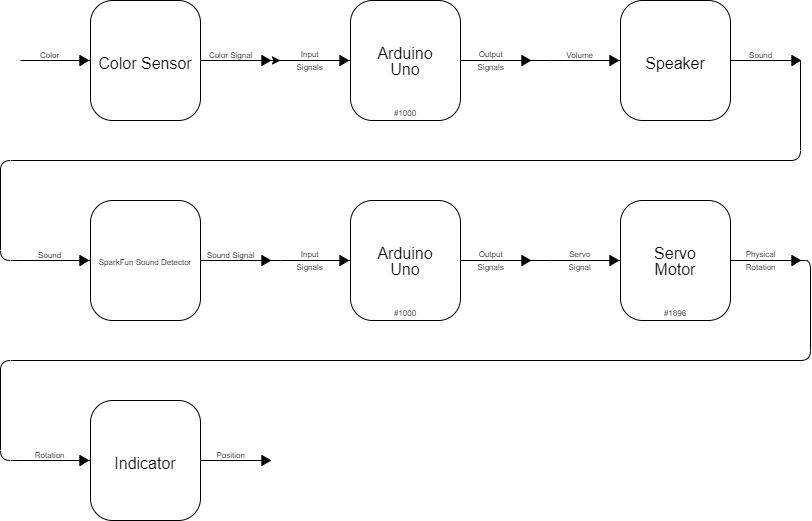
This double transducer is a machine that can read a color, map the color to a sound, and then map the volume of the sound to a rotation angle.
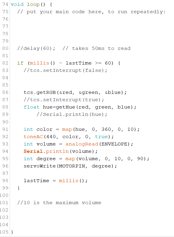
Coding process
Discussion
Something that was quite easy was coming up with the idea. Transducers seem to be quite common in the world around us (even though most transducers are single transducers, or so it seems); we just pulled from transducers that we have seen from the past, and the commonality of volume as a signal mechanism was very helpful in brainstorming ideas. Something that was hard was the process of coding the project. We ran into some issues with the libraries that we were using due to our physical components and the requirements of each component. We had to reach out to the Professor in order to resolve this problem. A tweak that would have changed the direction of this entirely would have been the emphasis on code in the beginning. Our group focused on building first rather than testing little parts, which resulted in us having to debug a massive amount of problems that were all inter-related. In terms of our creative growth, we were able to find useful applications for things that we found in real life. In terms of our technical growth, we were both able to become more familiar with the process of turning an idea into something physical! Next time, we would like to grow more in the efficiency process. We skipped a lot of steps, as well as performed many important steps out of order. As a result, we were less efficient than we could have been. Overall, however, the process was quite fun and interactive. We engaged in several troubleshooting sessions – first it was establishing the pieces that we needed, as well as the wiring for them. We had to go onto the websites of each piece to understand how the wiring and the code worked. Secondly, as mentioned previously, we had to focus on coding. Since C is pretty nit–picky sometimes, we had to make sure that everything that we were coding was intentional and not full of things that were unnecessary. In the end, our code was quite shorter than the beginning brainstorming session.
Functional Block Diagram
Schematic Diagram
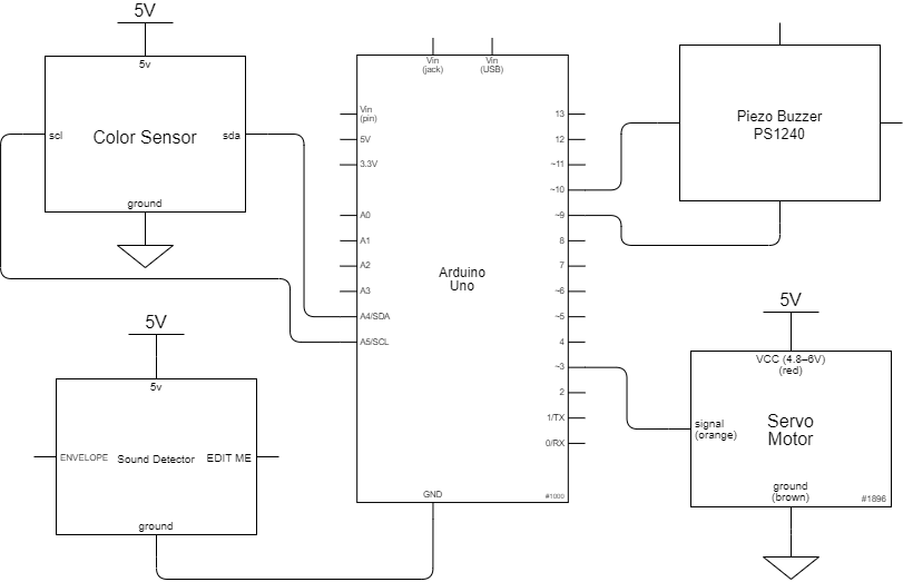
Double Transducer: Color to Rotational Position

// this includes all of the necessary libraries and sub-portions
#include <Wire.h>
#include "Adafruit_TCS34725.h"
#include <toneAC.h>
#include <LiquidCrystal_I2C.h>

// the following lines introduce global variables that have a baseline value of 0; this will be adjusted in local code later.
Adafruit_TCS34725 tcs = Adafruit_TCS34725(TCS34725_INTEGRATIONTIME_50MS, TCS34725_GAIN_4X);
unsigned long lastTime = 0;
unsigned long lastQuarterTime = 0;
float red, green, blue=0;
float hue=0;
LiquidCrystal_I2C screen(0x27, 16, 2);
const int MOTORPIN = 3;
int volume = 0;
int degree = 0;

#define ENVELOPE A0
#define MIN(a,b) (((a)<(b))?(a):(b))
#define MAX(a,b) (((a)>(b))?(a):(b))

//A function converting RGB value to Hue
float getHue(float red, float green, float blue) {

  float min = MIN(MIN(red, green), blue);
  float max = MAX(MAX(red, green), blue);

  if (min == max) {
    return 0;
  }
  float h = 0;
  if (max == red) {
    h = (green - blue) / (max - min);

  } else if (max == green) {
    h = 2 + (blue - red) / (max - min);

  } else {
    h = 4 + (red - green) / (max - min);
  }

  h = h * 60;
  if (h < 0) h = h + 360;

  return h;
}
// Code for servo motor without using library
void servoWrite(byte servoPin, byte servoDegree) {
  pinMode (servoPin, OUTPUT); // in case it's not already set

  const int INTERPULSEDELAY = 20; // typical delay between servo pulses

  static unsigned long lastPulseTime;

  if (millis() - lastPulseTime > INTERPULSEDELAY) {

    // turn degree input to pulse length output
    unsigned int pulseWait = map(servoDegree, 0, 180, 544, 2400);

    // transmit pulse of specified length
    digitalWrite(servoPin, HIGH);
    delayMicroseconds(pulseWait);
    digitalWrite(servoPin, LOW);

    // reset timer
    lastPulseTime = millis();
  }
}


void setup() {
  // set up the LCD's number of columns and rows:
  screen.init();

  // turn on the backlight to start
  screen.backlight();

  // set cursor to home position, i.e. the upper left corner
  screen.home();

  pinMode(MOTORPIN, OUTPUT);
  pinMode(ENVELOPE, INPUT);
  Serial.begin(9600);
}

void loop() {

// get hue value of the color
    tcs.getRGB(&red, &green, &blue);
    hue = getHue(red, green, blue);
    int color = map(hue, 0, 360, 0, 10);
// make speaker to make a sound
    toneAC(440, color, 0, true);
    volume = analogRead(ENVELOPE);
// mapping the volume signal into the degree signal
    degree = map(volume, 0, 10, 0, 90);
    servoWrite(MOTORPIN, degree);

// to display the necessary indicators onto the led
  if (millis() - lastQuarterTime >= 25) {
    screen.setCursor(0, 0);
    screen.print((String)"i:" + (int)hue + "  m:" + volume);
    screen.setCursor(1, 9);
    screen.print((String)"     " + (int)hue + "  o:" + degree);
    lastTime = millis();

  }

}
