Images and Videos
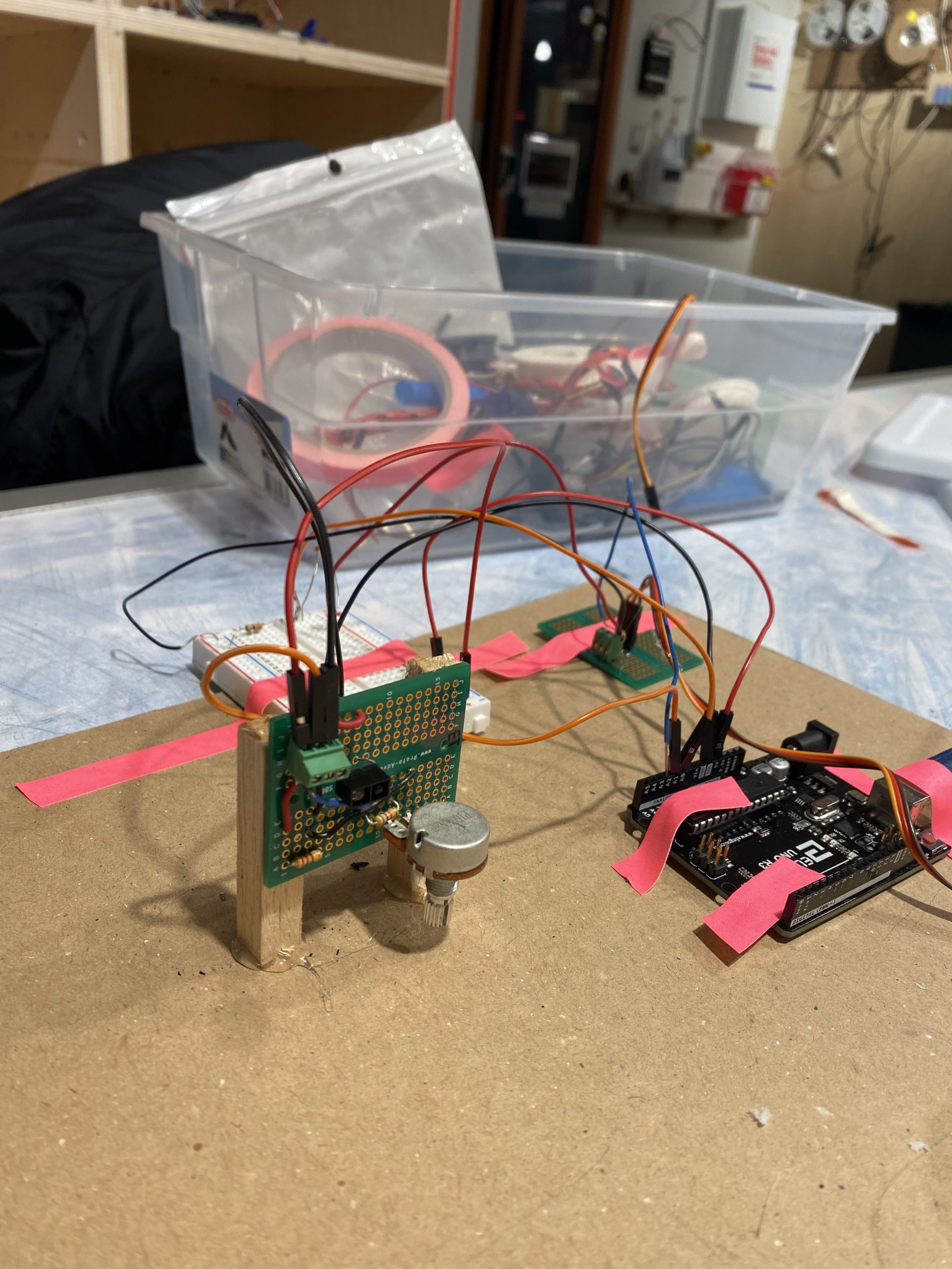
Tristan’s Final
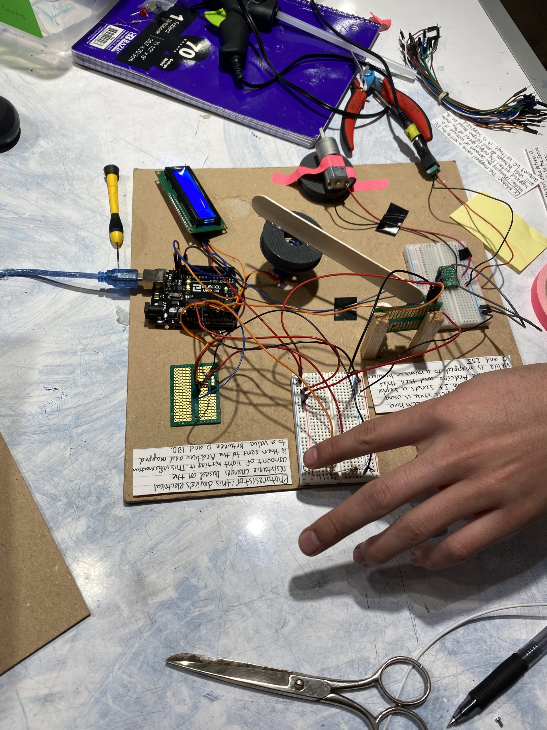
Nicole’s Final
Close up Image of Infrared Proximity Sensor
Close up Image of DC Motor and Motor Driver
Description
This Double Transducer takes in the brightness of light as an input and converts that into a rotational position and then finally converts that rotational position into a rotational speed. A photoresistor detects the brightness of light hitting it which is then converted to a rotational position between 0 and 180 degrees. The servo motor rotates a popsicle stick to this position and an IR sensor detects how far away the popsicle stick is. The IR sensor sends this information back to the Arduino and the Arduino maps this value to an amount of voltage. This voltage is then sent to a DC motor, the transducer’s final output. Based on the voltage supplied the rotational speed of the DC motor varies between 20 and 60 rpm.
Progress Pictures
Figuring out the distance between the IR sensor and popsicle stick.
Having trouble with pulley system.
We tested many different layouts for the components on the board to determine which was the most sensible.
Testing the photoresistor range of inputs to determine the range to use in the map function
Discussion
Our final project was a successful double transducer but there were many unforeseen challenges and modifications we had to make to our original idea. The preliminary middle step was to have a servo motor rotate a pulley, moving an index card back and forth. In theory this seemed like a simple mechanical system to construct, however all of our available options for a rope did not work. There was too much friction between the rope and the 3-D printed part for the pulley to successfully rotate the rope. Unfortunately, we had to scrap the pulley system idea and come up with another way for the servo motor to move the popsicle stick to various positions. At this point we had already wired the IR sensor and written the code for it so we didn’t want to rethink the entire middle step. We decided to instead attach the popsicle stick directly to the servo motor and then position the IR sensor to detect how far away it is. This ended up being much easier to execute than our original idea and was also a more reliable system. Being forced to deviate from our original idea was unsettling at first but worked out for the best in the end. Having to pivot taught us that you will often have to rethink and rework your original plan and to be prepared for failure when you attempt to execute your ideas. The importance of having an adaptable mindset is just as important as the planning process when working on physical computing projects.
Another misstep we faced was due to soldering. I did not truly understand the importance of precision when soldering until an overlooked error led to me short circuiting my Arduino. At first I did not understand why attaching the board I had soldered to my Arduino resulted in my Arduino immediately shutting down. My first instinct was that it was a faulty wire, but after testing all my wires and all of them working I knew it had to be from the way I soldered. When I looked at my soldering more closely I realized that there was melted metal connecting ground and power which was causing the entire system to fail. Surely enough when I fixed this error the board and the Arduino started working again. This misstep taught me it is important to not rush soldering and if a system is failing to check if it’s from a soldering error.
Writing the code was straightforward and didn’t present many challenges. However, determining the ranges to use in the map function was more difficult than anticipated and required more trial and error than expected. A lot of times our transducer not working was attributed to inaccurate ranges. At first we struggled to identify the optimal range for the transducer to work. As we continued to aimlessly plug and chug different numbers we realized that by interacting with the device we would get a better understanding of what values are needed for the map function. Another challenge was that the values of the inputs in the system, the photoresistor and IR sensor were often changing drastically. We learned that the IR sensor’s values were changing due to the potentiometer moving so we made sure it was more secured in one position. The photoresitor’s values were changing due to a change of environment, however as long as the transducer was in the classroom the same range of values worked. Adjusting the ranges taught us how to be more systematic about how we test values for inputs and outputs for the future.
Prior to this project, we both had limited experience with wiring inputs and outputs to the Arduino. From working on the double transducer we learned how to wire and program a photoresistor, IR sensor, LCD display, servo motor, and DC motor. This experience made both of us more comfortable with the challenges that come along with using these various inputs and outputs. For this project particularly, the DC motor presented the most frustration. Unlike the servo motor that can be wired directly to the breadboard, the DC motor needed an additional power source and assistance from a motor driver in order to work. We spent a while toying around with the DC motor before learning that its failure was due to the absence of a motor driver. This set back taught us to not expect similar inputs and outputs to work the same. The DC motor and servo motor may function similarly but their wiring and software are different. This project was a valuable introduction to physical computing and allowed both of us to become familiar with using several new inputs and outputs.
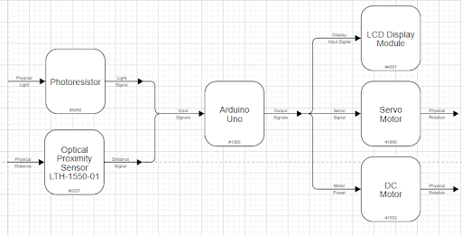
Functional Block Diagram
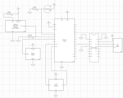
Schematic
Code
/*
   Double Transducer: Light Brightness -> Rotational Speed

   Team Members: Nicole Monaco, Tristan Hineman

   Description:
    The program is disigned to recieve input from the photoresistor and covert
    the value to an angle for the servo motor with a popsicle stick to move to
    where then an infrared proximity sensor will detect the distance of the popsicle stick and convert that to
    a rotational speed between 20 and 60rpm for the DC motor to output.

   Pin Mapping Table:

   Arduino pin  |  description
   -------------|-------------
   A0             Photoresistor

   A2             Servo Motor
   A1             Infrared Proximity Sensor

   5              Driver chip for DC Motor

   SDA            SDA pin, LCD Display
   SCL            SCL pin, LCD Display


   References:
   https://courses.ideate.cmu.edu/60-223/s2022/tutorials/reading-a-photoresistor
   https://courses.ideate.cmu.edu/60-223/s2022/tutorials/servo
   https://courses.ideate.cmu.edu/60-223/s2022/tutorials/IR-proximity-sensor
   https://courses.ideate.cmu.edu/60-223/s2022/tutorials/I2C-lcd
*/

//Libraries
#include <LiquidCrystal_I2C.h>
#include <Servo.h>
Servo servoMotor;

//Pin for photoresistor
const int photoPIN = A0;

//Pin for infrared proximity sensor
const int irPIN = A1;

//Pin for servo motor
const int servoPIN = A2;

//Pin for dc motor driver chip
const int dcPIN = 5;

//Variables for LCD display
unsigned long lastServoTime = 0;
unsigned long lastIRTime = 0;
unsigned long lastDCTime = 0;
unsigned long lastLCDTime = 0;

//Setup to LCD display
LiquidCrystal_I2C screen(0x27, 16, 2); // create LCD display object
void updateScreen(int photoVal, int servoPos, int IRreadVal, int DCSpeed) {
  screen.setCursor(3, 0);
  screen.print(map(photoVal, 80, 300, 0, 90));
  screen.setCursor(11, 0);
  screen.print(servoPos);
  screen.setCursor(3, 1);
  screen.print(map(IRreadVal, 45, 960, 0, 90));
  screen.print(map(DCSpeed, 50, 80, 36, 60));
}

void setup() {

  //Pin setup
  pinMode(photoPIN, INPUT);
  pinMode(irPIN, INPUT);
  pinMode(dcPIN, OUTPUT);
  servoMotor.attach(servoPIN);

  Serial.begin(9600);

  //LCD screen initialization
  screen.init();
  screen.backlight();
  screen.home();
  screen.print("i:");
  screen.setCursor(7, 0);
  screen.print("m1:");
  screen.setCursor(0, 1);
  screen.print("m2:");
  screen.setCursor(7, 1);
  screen.print("o:");
}

void loop() {

  screen.setCursor(5, 0);
  screen.print (" ");

  //Variable to store photoresistor value
  int photoVal = analogRead(photoPIN);
  Serial.print(photoVal);
  Serial.print("     ");

  //Variable to set servo position
  int servoPos;

  //Adjust the angle of the servo motor according to the registered light brightness from the photoresistor
  if (millis() - lastServoTime >= 500) {
    servoPos = map(photoVal, 80, 300, 0, 45);
    servoMotor.write(servoPos);
    lastServoTime = millis();
  }

  //Variable to store infrared proximity sensor value
  int IRreadVal;

  //Read and print infrared proximity sensor value
  IRreadVal = analogRead(irPIN);
  if (millis() - lastIRTime >= 50) {
    lastIRTime = millis();
  }
  Serial.println(IRreadVal);

  //Variable to set the speed of the DC motor
  int DCSpeed;

  //Adjust the speed of the dc motor accoding to the distance from the infrared proximity sensor
  if (millis() - lastDCTime >= 500) {
    DCSpeed = map(IRreadVal, 45, 960, 50, 80);
    analogWrite(dcPIN, DCSpeed);
    lastDCTime = millis();
  }

  //display on the LCD
  if (millis() - lastLCDTime >= 500) {
    updateScreen(photoVal, servoPos, IRreadVal, DCSpeed);
    lastLCDTime = millis();
  }
}