60223 Project 1 – David Wu and Jiaying (Vina) Wei
Double Transducer: Flight of the Bumblebeep
This double transducer takes in a rotational input of 10-80 degrees, and outputs a pitch from 200-2000 Hz. It goes through a middle step of LED brightness, and detects this brightness with a photoresistor.
Final Project Photos
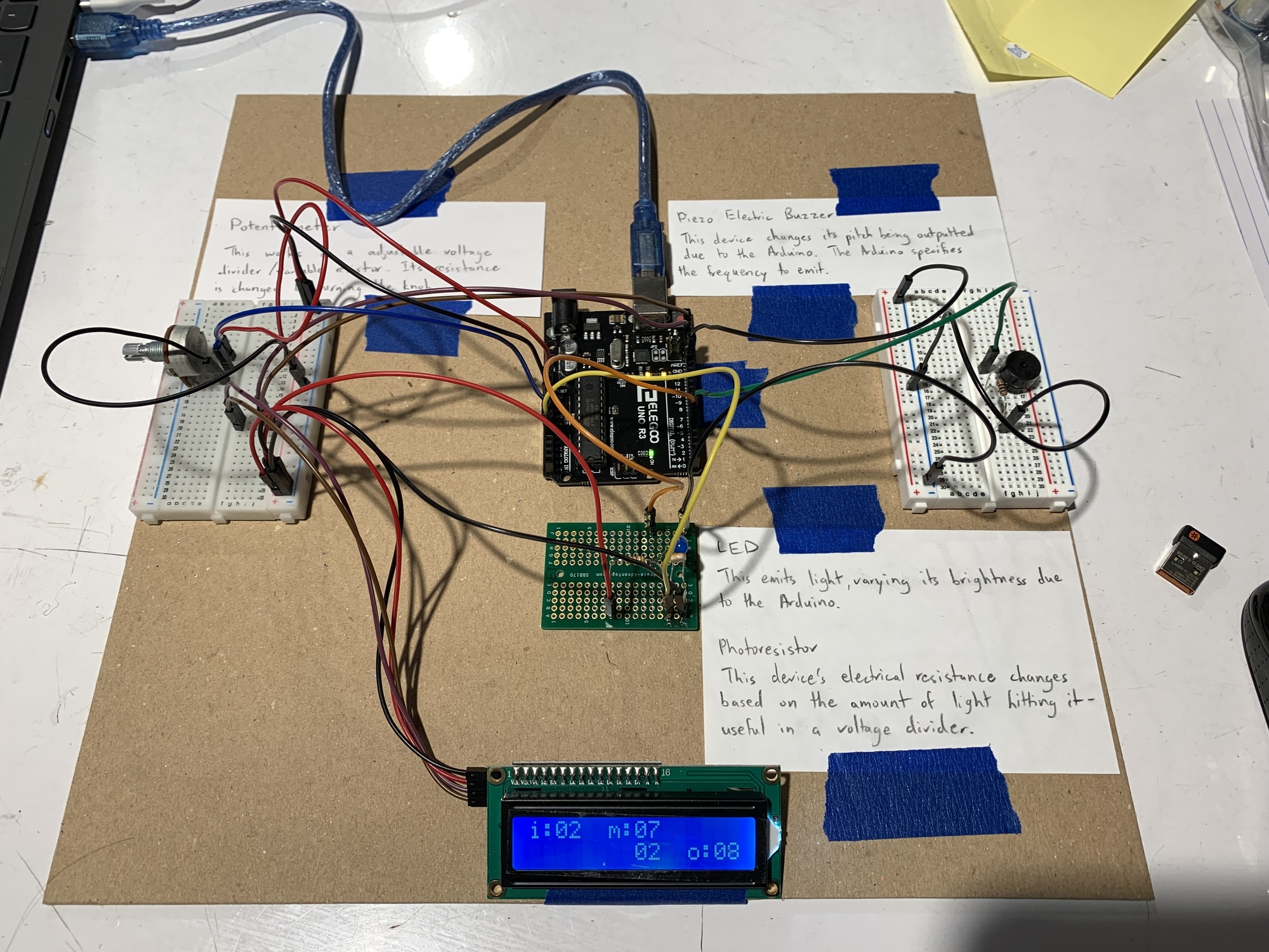
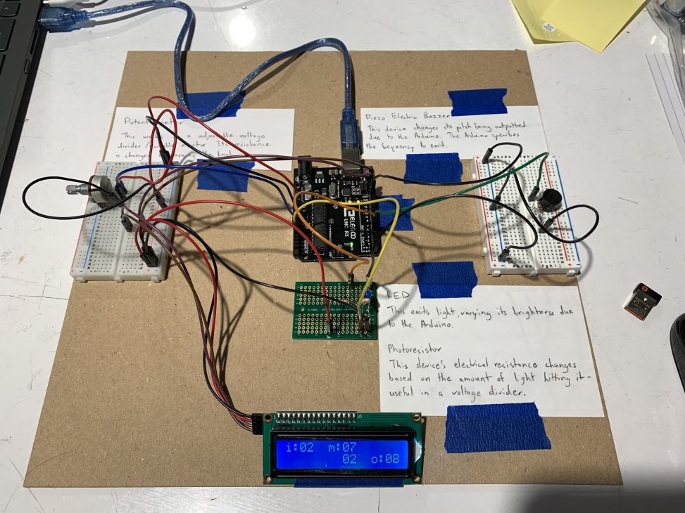
David’s Final Version. It contains no restrictions on the input range.
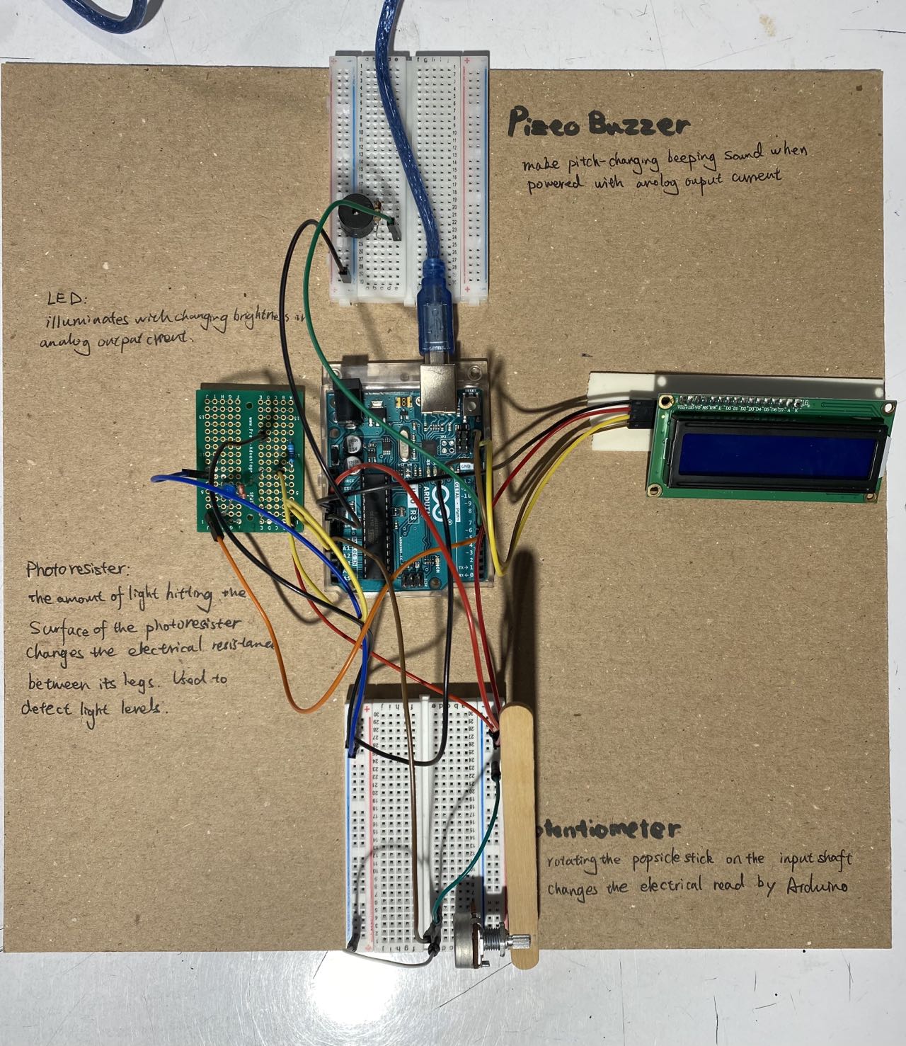
Vina’s Final Version. It is more optimized for a certain 70 degree range.
Detailed Component Images
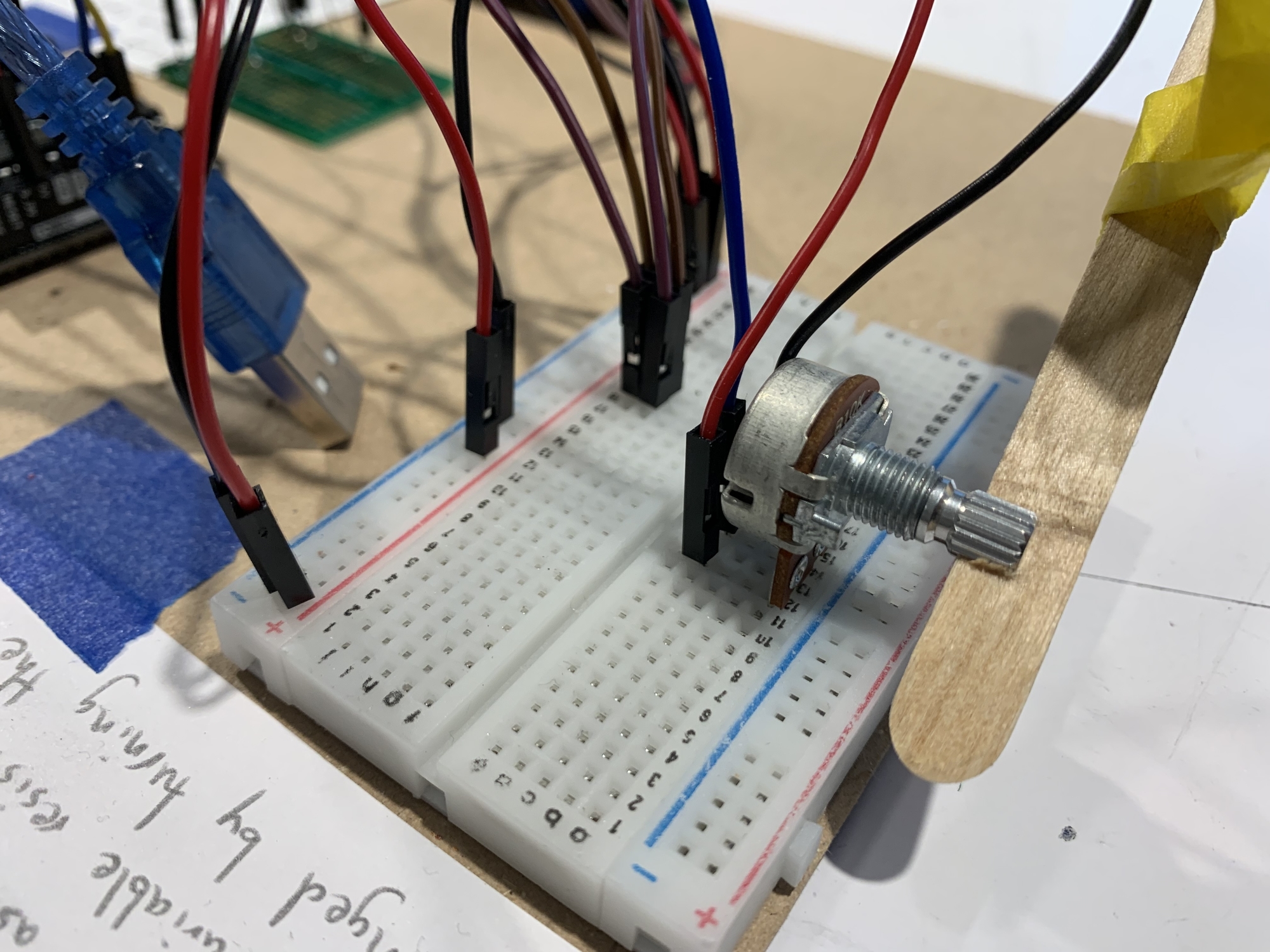
Input Area. A popsicle stick wedged in a potentiometer served to measure a change in angle from the input.
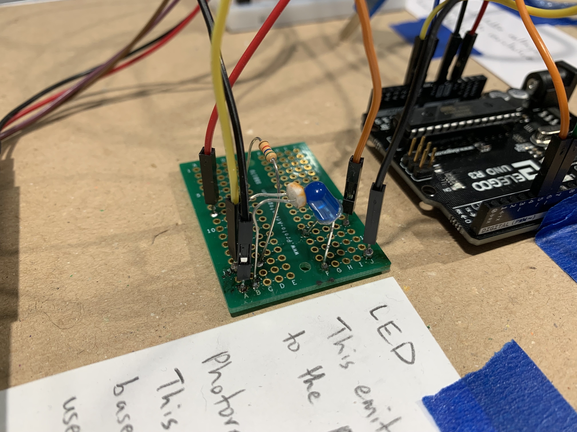
Middle Step Area. A LED and a photoresistor are soldered together, and bent to face each other for maximum light detection.
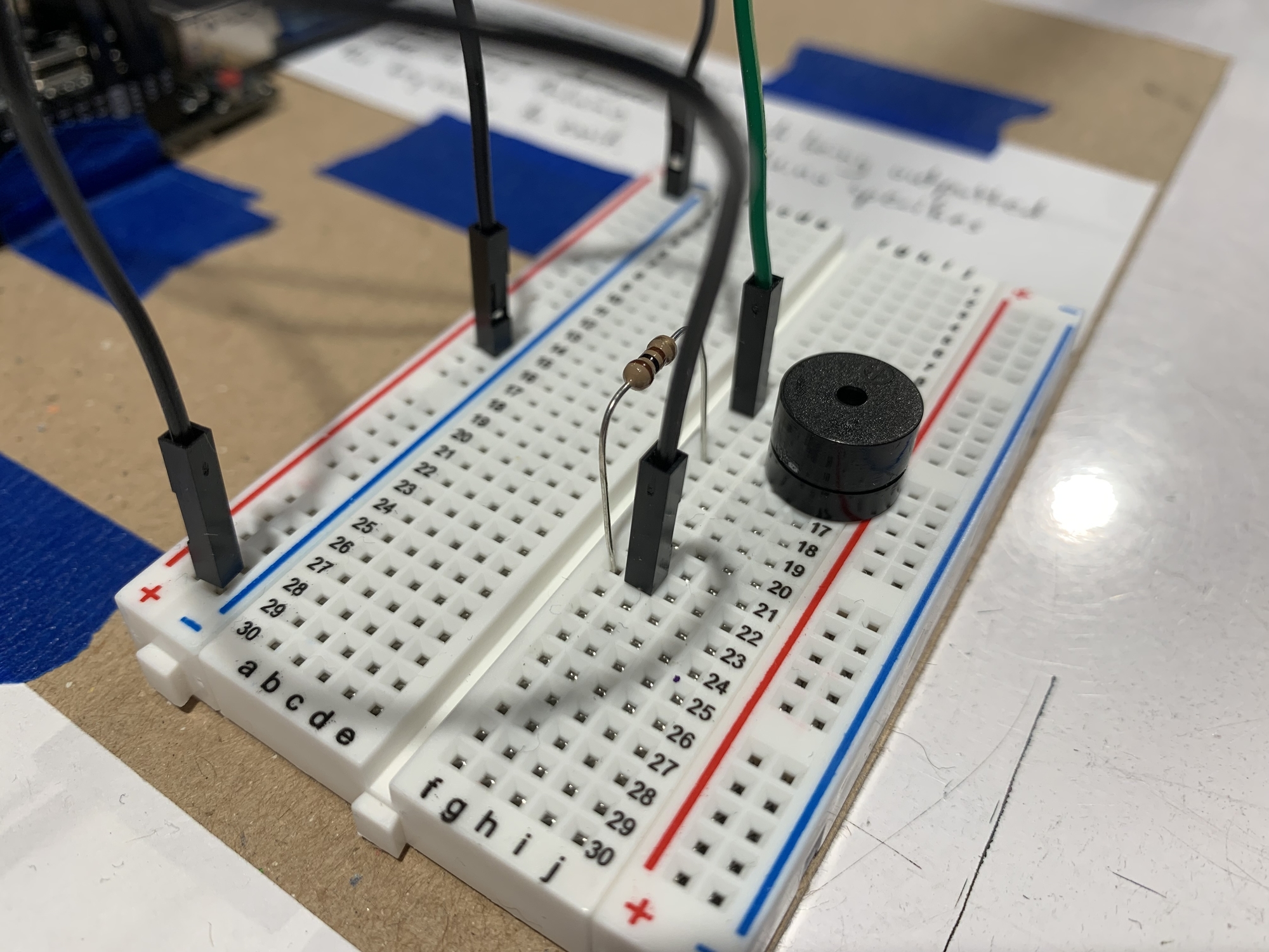
Output Area. A piezo electric buzzer emits a variable pitch depending on the output signal.
Video Demonstrations
David’s Version:
Vina’s Version:
Simple Narrative Description
The device takes in something turning and puts out a noise from a speaker. A popsicle stick can be turned around. As it turns towards the right, a blue light glows brighter, which is detected and converted into a higher pitch. As it turns left, the blue light becomes dimmer, and a lower pitch is played.
Progress Images
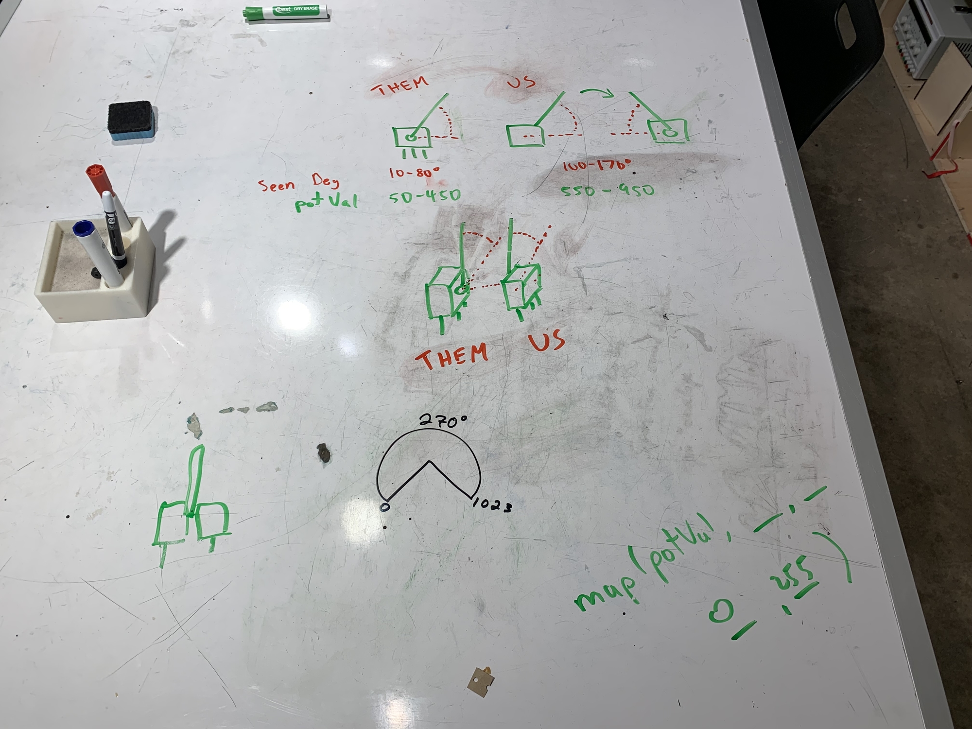
David Progress Image 1. This was the discussion and problem-solving behind the concern of inverted input ranges when linking to other devices.
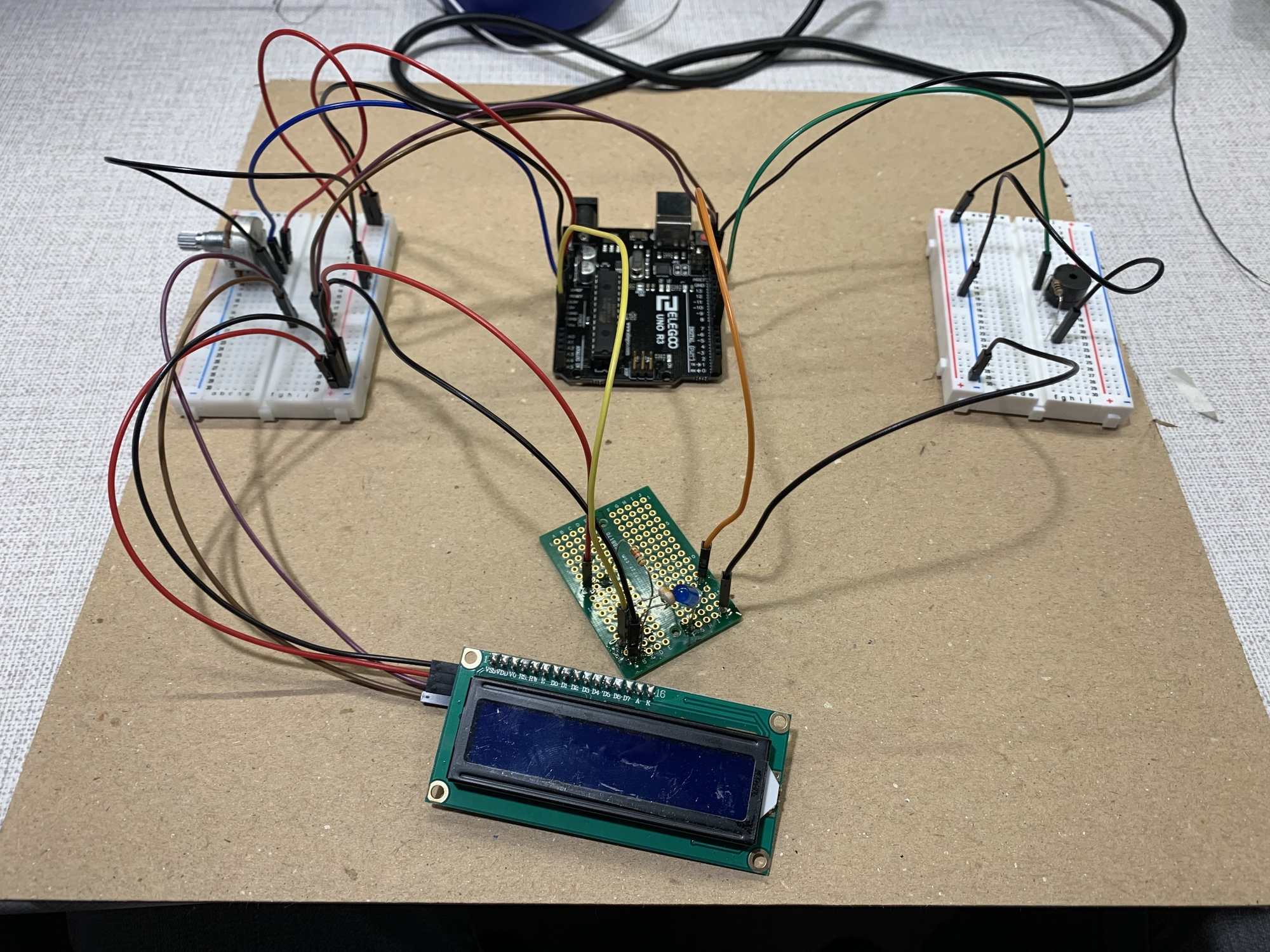
David Progress Image 2. Everything is wired up, and placement is being played around with.
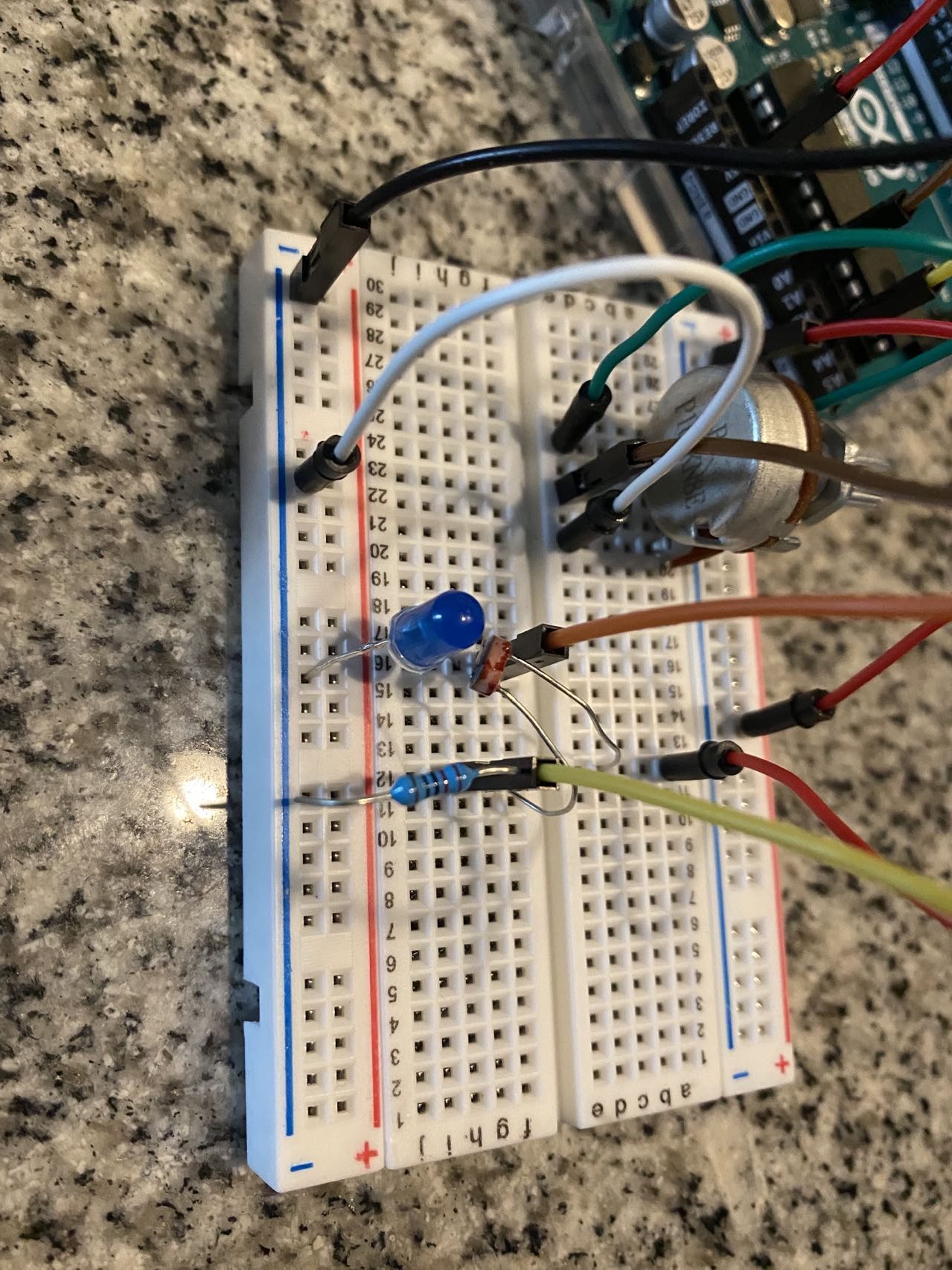
Vina Progress Image 1. This was initial circuit design to test if the input worked- the LED has not been bent to face the photoresistor yet.
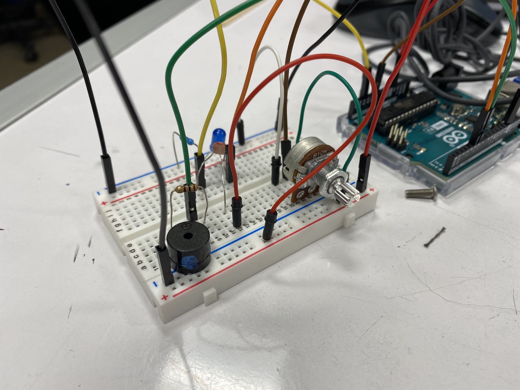
Vina Progress Image 2. Everything, from input to output, is placed on a single breadboard to test if the code would work.
Discussion and Reflection
In general, the project was relatively straightforward. The transmission from the input to the output turned out rather smooth, and most connections were through the Arduino (for example, from initial input to middle input, and from middle output to final output), making potential mechanical errors to be nearly none. As such, most struggles ended up during the programming stage, particularly the mapping of sensory input/outputs.
Mapping sensory inputs/outputs was crucial for trying to maintain a good LCD display from 0-99, but also as accurate a transmission of signals as well. However, it proved to be challenging because of inconsistency. For some strange reasons, the photoresistor used to detect the LED brightness seemed to almost recalibrate itself when the device was in use- causing values to go haywire and the mapping to shoot past 0 or 99. It was also affected by environmental light, a factor that was not particularly noticed until the device was used outside of the worktable it was created at (the calibration so finely made was then incorrect). In retrospect, it would have been smart to build a black box for the middle step, which would help to standardize calibration (and perhaps eased the inconsistencies). While this had been an initial thought, it had been disregarded, since bending the photoresistor and LED to face each other seemed to be enough for the signal to transmit. While not entirely wrong in broad considerations, it was incorrect when considering finer details. In the end, to resolve this issue, we used some conditional statements to bound the value to 0-99, and using a lot of calibrating, the device was nearly perfectly mapped, with the display showing from about 2-99.
Another trouble was during consideration of how the device would eventually be linked to the other devices. While technically outside the required scope of the project, it was still a consideration, mostly for courtesy and being a team player. The trouble was that while our designated input was from 10 to 80 degrees, this range of 70 degrees would differ due to a mirroring issue. Our input would be in a counterclockwise direction, like a usual Cartesian coordinate system, but the previous team’s output, should they approach the same intuitive counterclockwise direction, would be mirrored- they would be our input’s 170 to 100 degrees. As such, should we strictly map our input to how we viewed it, it would be completely useless when attached to the previous team. Thus, we created two devices- one of which was more finely tuned to 10 to 80 degrees, which would have the most accurate standards for the individual project grading; one of which was mapped to the entire range, so that the previous team’s input could be taken in, regardless of which direction and which range they ended up using. This allowed us to tackle both challenges at the same time, at the expense of writing two slightly different programs. Mechanically, they were still identical.
Other than these struggles, the project proved to be an exciting test and learning opportunity for the sensors and materials available to us. We discovered many things amidst our adventures: Arduino functions, photoresistors, different blades to whittle popsicle sticks- even the fact that a certain piezo buzzer sounded like “Flight of the Bumblebee” was an unexpected, but fun way to obtain the name of our project. All in all, while the process did not go as smoothly as it could have, the end result worked splendidly, and we are very proud of that.
Functional Block Diagram and Schematic
Project Code (David’s Version)
This code is optimized to have the input be the entirety of the potentiometer range.
/* Project Title: Flight of the Bumblebeep
 * Creators: David Wu and Jiaying (Vina) Wei
 *
 * This code takes in the input of a potentiometer turning, and maps
 * it to output the brightness of an LED. It then reads in the value
 * of a photoresistor, which should be reading the aforementioned LED,
 * and maps it to output the pitch of a piezo buzzer. The four steps
 * are all mapped to 0-99 and displayed on a LCD display.
 *
 * Pin Mapping:
 * Potentiometer : A0
 * Photoresistor : A1
 * LED           : 5
 * Piezo Buzzer  : 6
 * LCD SDA/SCL   : SDA/SCL       :
 *
 * Credit to CMU 60-223 Professor Zacharias's code for the LCD Display
 */

#include <Wire.h>
#include <LiquidCrystal_I2C.h>


const int POTPIN = A0; // potentiometer intput
const int PHOTOPIN = A1;// photoresistor input
const int LEDPIN = 5; // LED output
const int SPEAKPIN = 6; // speaker/buzzer output
unsigned long lastDispTime = 0; // to stop LCD flickering

LiquidCrystal_I2C screen(0x27, 16, 2);

void setup() {
  pinMode(POTPIN,INPUT);
  pinMode(LEDPIN,OUTPUT);
  pinMode(PHOTOPIN,INPUT);
  pinMode(SPEAKPIN, OUTPUT);
  Serial.begin(9600);


  // display code
  // initialize the screen and backlight
  screen.init();
  screen.backlight();

  // initial variable display
  screen.home();
  screen.print("i:"); // potentiometer
  screen.setCursor(6, 0);
  screen.print("m:"); // LED brightness
  screen.setCursor(8, 1);
  screen.print(""); // displayed brightness
  screen.setCursor(12, 1);
  screen.print("o:"); // pitch
}

void loop() {
  // read potentiometer with popsicle stick
  int potVal = analogRead(POTPIN);

  // convert potentiometer to LED brightness
  int LEDBright = map(potVal,0,1000,0,250);
  analogWrite(LEDPIN,LEDBright);

  // detect the brightness using photoresistor
  int detectBright = analogRead(PHOTOPIN);

  // convert detected brightness to pitch
  int pitch = map(detectBright,43,270,200,2000);
  tone(SPEAKPIN, pitch);

  // display code
  // change display 8 times a second
  if (millis() - lastDispTime >= 125) {
    // adjusting values for display purposes
    int potValAdj = map(potVal, 100, 1022, 0, 99);
    if (potValAdj < 0) potValAdj = 0;
    if (potValAdj > 99) potValAdj = 99;

    int LEDBrightAdj = map(LEDBright, 10, 255, 0, 99);
    if (LEDBrightAdj < 0) LEDBrightAdj = 0;
    if (LEDBrightAdj > 99) LEDBrightAdj = 99;

    int detectBrightAdj = map(detectBright, 230, 70, 0, 99);
    if (detectBrightAdj < 0) detectBrightAdj = 0;
    if (detectBrightAdj > 99) detectBrightAdj = 99;

    int pitchAdj = map(pitch, 1700, 500, 0, 99);
    if (pitchAdj < 0) pitchAdj = 0;
    if (pitchAdj > 99) pitchAdj = 99;

    // display formatting
    screen.home();
    screen.print("i:"); // potentiometer
    screen.print(potValAdj);
    screen.setCursor(6, 0);
    screen.print("m:"); // LED brightness
    screen.print(LEDBrightAdj);
    screen.setCursor(8, 1);
    screen.print(detectBrightAdj); // displayed brightness
    screen.setCursor(12, 1);
    screen.print("o:"); // pitch
    screen.print(pitchAdj);
    lastDispTime = millis();
  }
}
