Do you have the trouble of having too many lipsticks and not knowing which one to use? Try this lipstick container! It can pick out your lucky color of the day for you!
Overall Photos
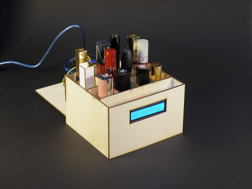
the overall image of the lipstick container
Detailed Photos
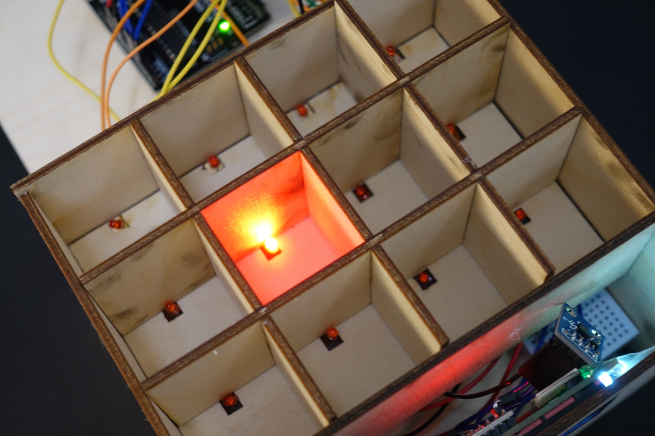
what the bottom of the container looks like
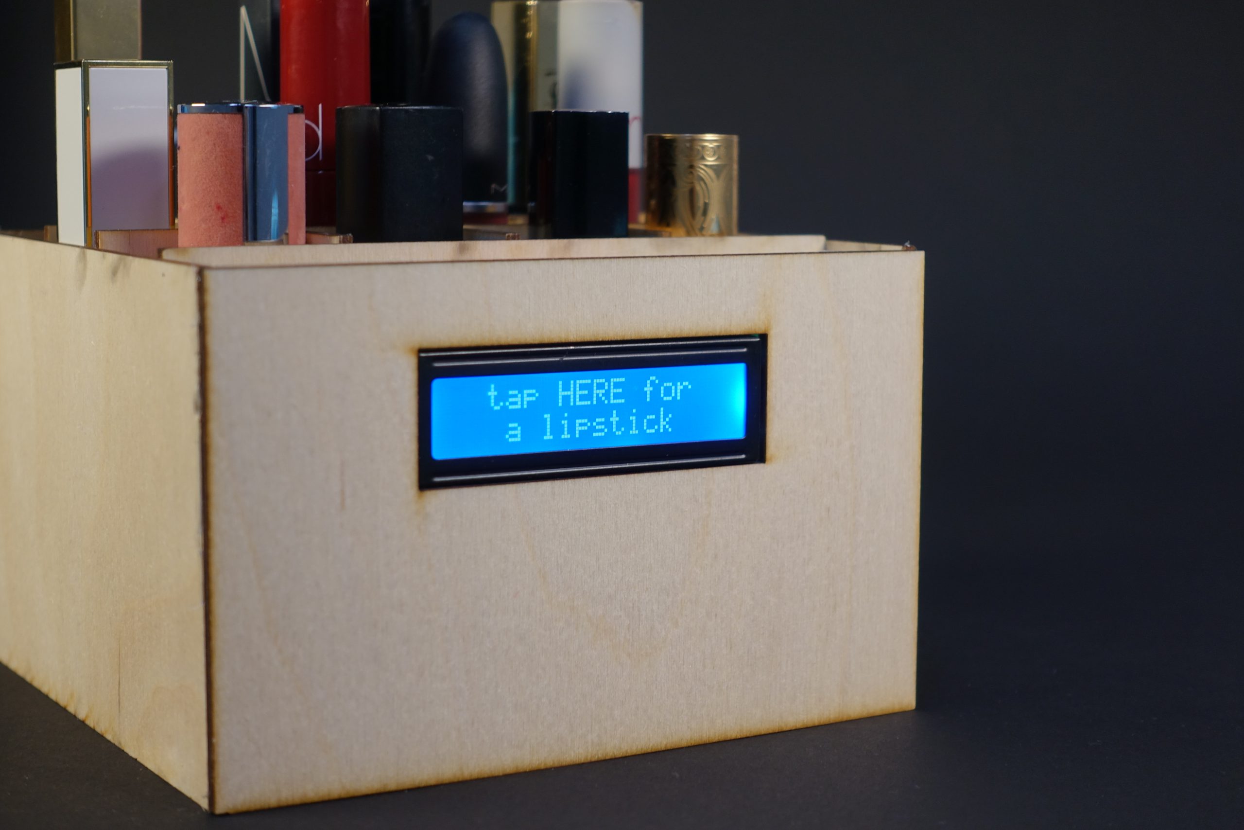
LCD display first version
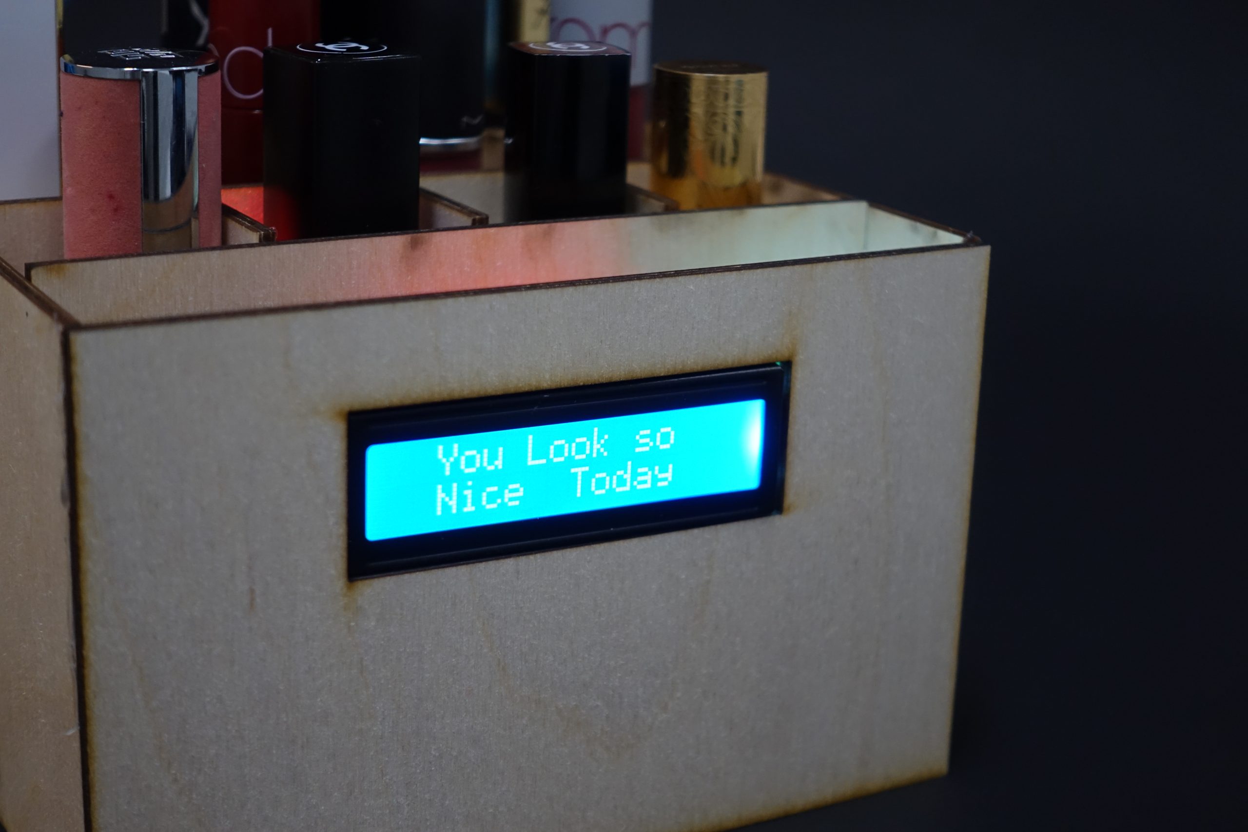
LCD display second version
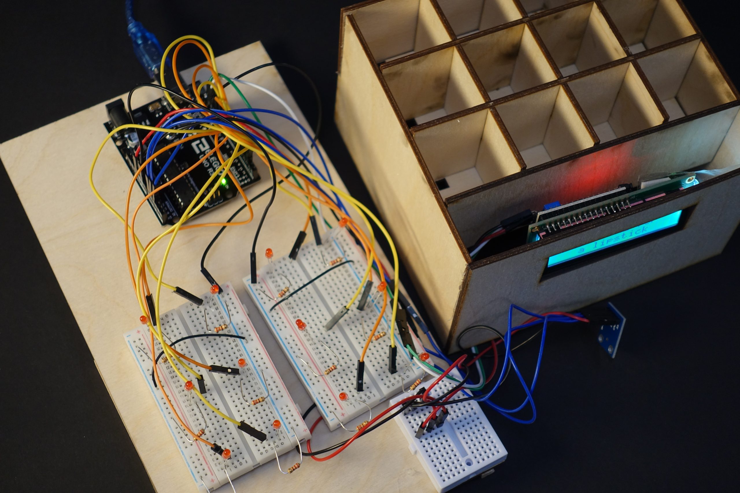
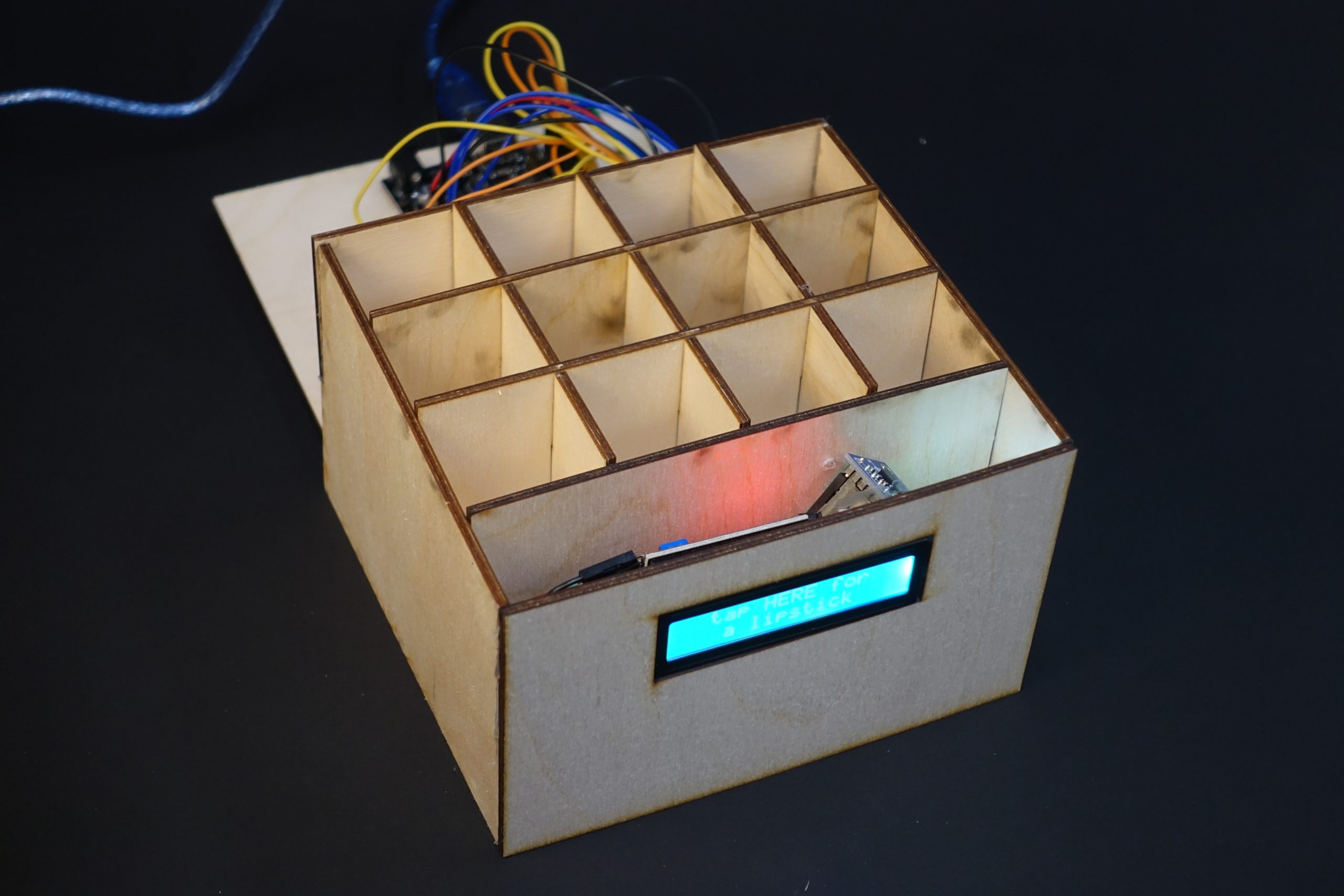
separation of the electrical part and the container
Process Images and Review
First Decision Point
At first, besides randomly choosing the lipstick, I designed another feature for the container. Since it was easy for me to mess up my table after make-up, I wish the container could remind me of putting the lipstick back in its place after using it. Therefore, it would beep after 2 minutes if the room of the container was still empty. I found that if I wanted to make it, it needed much more space for the wiring part which made the container huge. Meanwhile, this feature was not as attractive as the random-choosing one, so I finally canceled it.
Second Decision Point
Since I had to connect 12 LED lights, one LCD display, and one ADXL335 analog accelerometer, I wiring part was very complicated and hard to follow. Therefore at that time, I decided to do the soldering to make it look logical and clear.
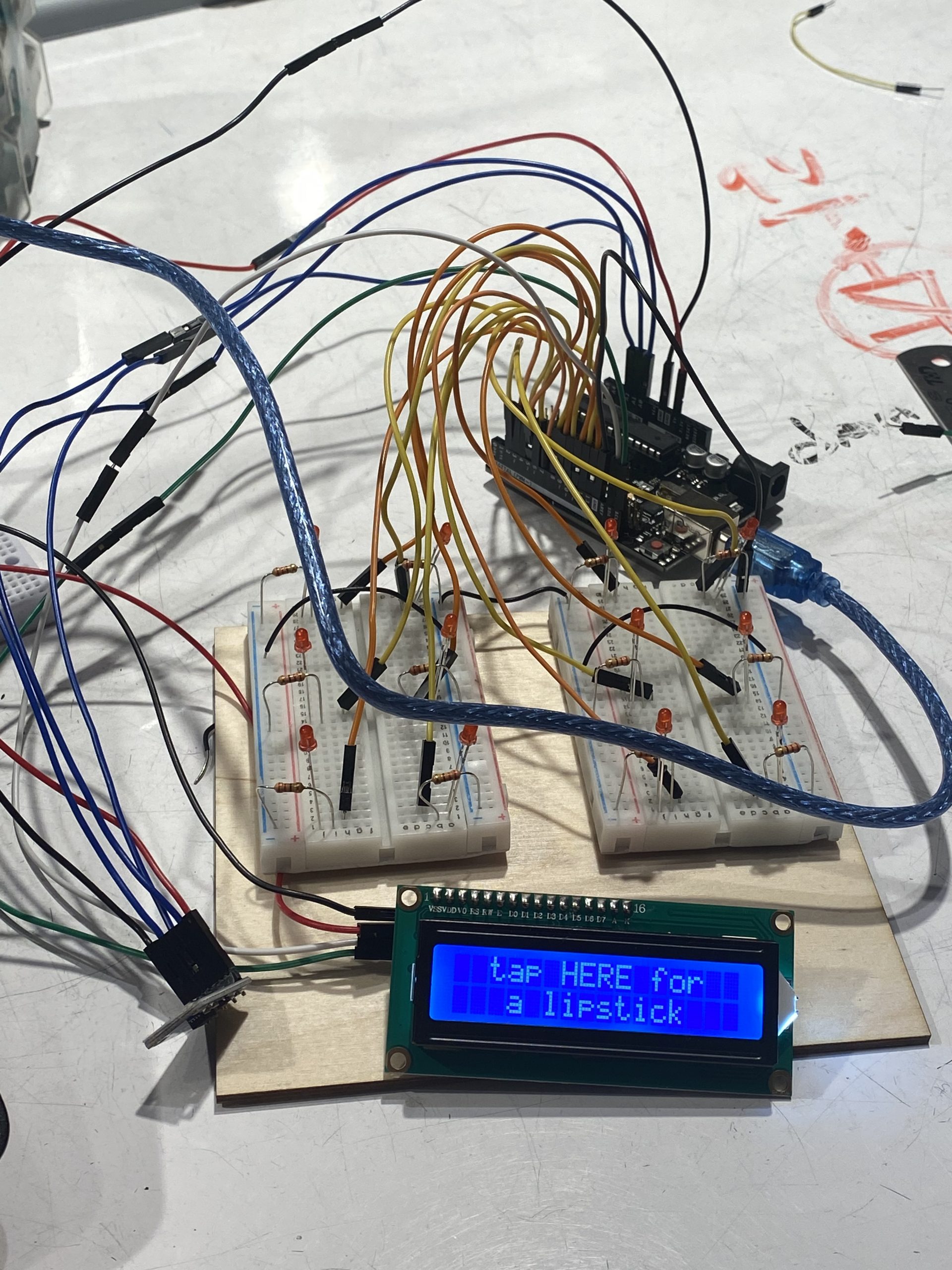
wiring on normal breadboards
Honestly, I tried to do the soldering and finished all about it. But the results were not satisfying which made me realize soldering is not suitable for all the situations. Because there was a certain distance between each LED, it was impossible to reduce the wiring part through soldering. Also, since the wiring part is at the bottom of the container, some wires were bent which made them easy to be broken. If it was broken, I have to do the soldering again (I did it almost 5-6 times). So finally I gave up the soldering idea and just used normal breadboards to connect them.
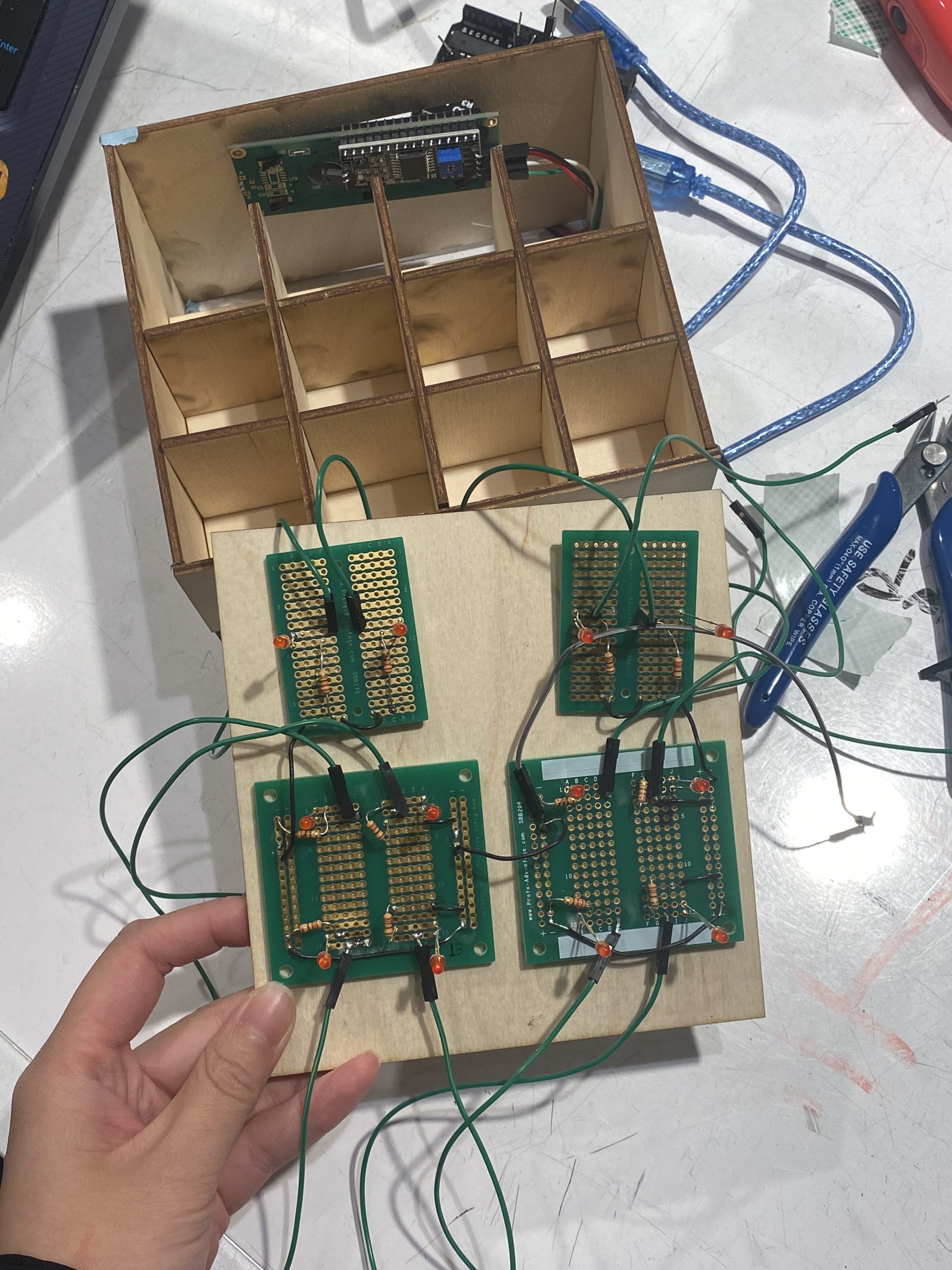
attempt of soldering
Process Highlights
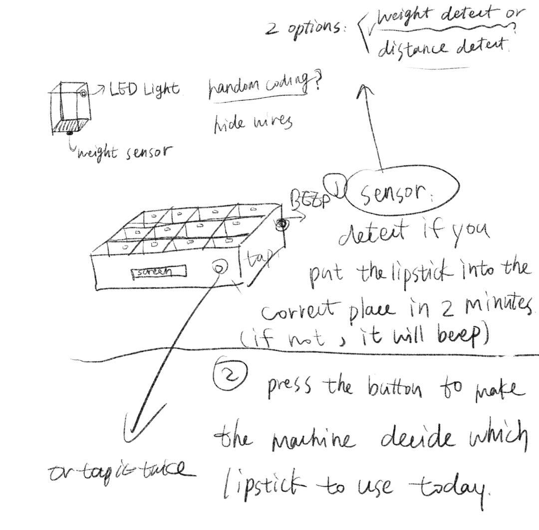
draft of the design
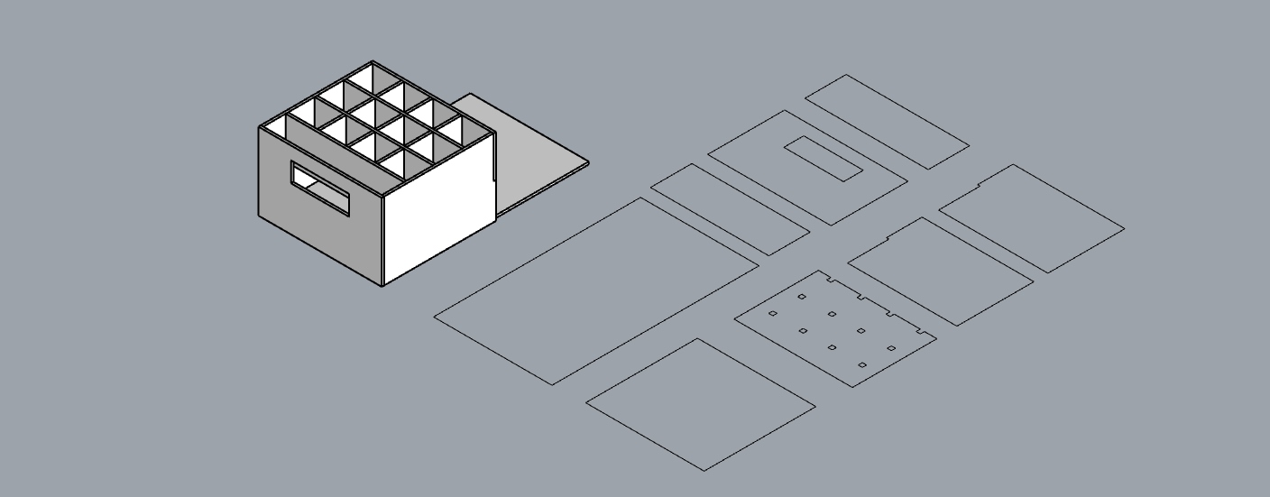
the model in Rhino
first time to make lights work successfully on breadboards
Discussion
Overall, I am really satisfied with what I created for this project. It can successfully solve my trouble of choosing which lipstick to use in the morning and make my day starts with surprise and fun lol. As an architecture student, it was not a hard part for me to build a model in both digital and physical ways and do laser cutting. The most difficult thing for me is writing the code to make my device work. It was my first time writing the code independently which made me get a deeper understanding of the logic of each step. Thanks to Zach, he explained how to turn the lights on in order and taught me how to do the random choosing process. He was so patient and encouraged me a lot which made me become confident with learning the coding language. Also, I got a better understanding of the loop function which made the LCD display show the information incorrect time.
I really enjoyed the discussion about the prototype with my classmates. They were so kind that gave me a bunch of encouragement as well as a lot of suggestions. For instance, someone suggested that I could use some tools to make the choice of lipstick based on the eye shadow I wear. I did think it is a good idea, a sensor can detect the color of eye shadow which could bring about a specific lipstick matching with all the makeup look. But what I want for the lipstick container is a totally surprising thing, you would not know any hints about which one to use before you tap the screen. A boy told me that I could add a screen to the container with some warm-hearted words on it. This suggestion was super useful so I add ‘You Look so Nice Today’ when finishing the choosing process.
If I had more time, I would add a power switch to the container to make it work only when I need it. Also, I would think about developing another type of container like the girl’s idea about matching with eye shadow. I truly think it will be cool and get in touch with many other interesting sensors and improve my coding abilities as well. Due to the limited time and energy, I could not complete all the good ideas so perfectly. I am really looking forward to the next project! I love new challenges and I believe, the new project will bring me a lot of inspiring thoughts and much more improvement about my abilities.
Technical information
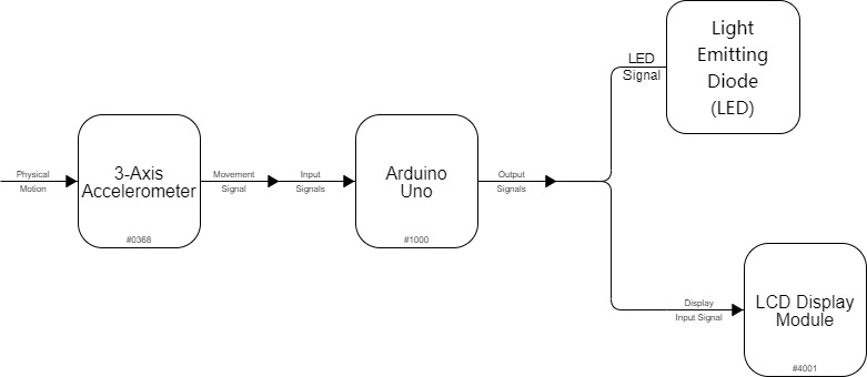
Block Diagram
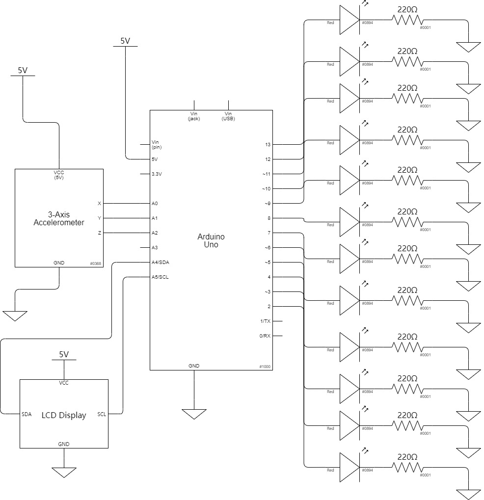
Schematic Diagram
Code
/*  60-223 Assistive Device
    Yongwen Dai
    Description: This code enables the movement of ADXL335 analog accelerometer to start the lights on. All the 12 lights will be on in order at the beginning and finally only one of them will be chosen randomly to be on. The LCD display shows 2 different information at beginning and end of choosing.
    Pin mapping:
    Arduino pin | type   | description
    ------------|--------|-------------
         A0       input     X axis of ADXL335 analog accelerometer
         A1       input     Y axis of ADXL335 analog accelerometer
         A2       input     Z axis of ADXL335 analog accelerometer
         2        output    LED light 1
         3        output    LED light 2
         4        output    LED light 3
         5        output    LED light 4
         6        output    LED light 5
         7        output    LED light 6
         8        output    LED light 7
         9        output    LED light 8
         10       output    LED light 9
         11       output    LED light 10
         12       output    LED light 11
         13       output    LED light 12

    The following sources were consulted to create our code:
    https://courses.ideate.cmu.edu/60-223/s2022/tutorials/ADXL335
    https://courses.ideate.cmu.edu/60-223/s2022/tutorials/I2C-lcd
*/


#include <Wire.h>
#include <LiquidCrystal_I2C.h>

/* Creates an LCD display object called "screen" with I2C address 0x27
   which is 16 columns wide and 2 rows tall. */
LiquidCrystal_I2C screen(0x27, 16, 2);


//pin names
int light1 = 2;
int light2 = 3;
int light3 = 4;
int light4 = 5;
int light5 = 6;
int light6 = 7;
int light7 = 8;
int light8 = 9;
int light9 = 10;
int light10 = 11;
int light11 = 12;
int light12 = 13;

const int XPIN = A0;
const int YPIN = A1;
const int ZPIN = A2;

int Y;

//other variables
int timeShowDecision = 2000;
int timeBlink = 80;

void setup()
{
  //set input ADXL335 pins
  pinMode(XPIN, INPUT);
  pinMode(YPIN, INPUT);
  pinMode(ZPIN, INPUT);
  //set LED output pins
  pinMode(light1, OUTPUT);
  pinMode(light2, OUTPUT);
  pinMode(light3, OUTPUT);
  pinMode(light4, OUTPUT);
  pinMode(light5, OUTPUT);
  pinMode(light6, OUTPUT);
  pinMode(light7, OUTPUT);
  pinMode(light8, OUTPUT);
  pinMode(light9, OUTPUT);
  pinMode(light10, OUTPUT);
  pinMode(light11, OUTPUT);
  pinMode(light12, OUTPUT);

  //initialize the serial communication:
  Serial.begin(9600);

  //set words for LCD screen
    screen.init();
    screen.backlight();
}

void loop()
{
  //LCD display will show some words to encourage you to tap the screen.
  screen.setCursor(2, 0);
  screen.print("tap HERE for");
  screen.setCursor(3, 1);
  screen.print("a lipstick");
  delay(3600);

  int newX =analogRead(XPIN);  //read from xpin
  delay(50);
  int newY =analogRead(YPIN);  //read from ypin
  delay(50);
  int newZ =analogRead(ZPIN);  //read from zpin
  delay(50);

  //YPIN will change if you tap the screen to make the ADXL335 analog accelerometer move,
  then all the 12 lights will be on in order.

  if(newY - Y > 2){
    digitalWrite(light1,HIGH);
    delay(timeBlink);
    digitalWrite(light1,LOW);
    delay(timeBlink);

    digitalWrite(light2,HIGH);
    delay(timeBlink);
    digitalWrite(light2,LOW);
    delay(timeBlink);

    digitalWrite(light3,HIGH);
    delay(timeBlink);
    digitalWrite(light3,LOW);
    delay(timeBlink);

    digitalWrite(light4,HIGH);
    delay(timeBlink);
    digitalWrite(light4,LOW);
    delay(timeBlink);

    digitalWrite(light5,HIGH);
    delay(timeBlink);
    digitalWrite(light5,LOW);
    delay(timeBlink);

    digitalWrite(light6,HIGH);
    delay(timeBlink);
    digitalWrite(light6,LOW);
    delay(timeBlink);

    digitalWrite(light7,HIGH);
    delay(timeBlink);
    digitalWrite(light7,LOW);
    delay(timeBlink);

    digitalWrite(light8,HIGH);
    delay(timeBlink);
    digitalWrite(light8,LOW);
    delay(timeBlink);

    digitalWrite(light9,HIGH);
    delay(timeBlink);
    digitalWrite(light9,LOW);
    delay(timeBlink);

    digitalWrite(light10,HIGH);
    delay(timeBlink);
    digitalWrite(light10,LOW);
    delay(timeBlink);

    digitalWrite(light11,HIGH);
    delay(timeBlink);
    digitalWrite(light11,LOW);
    delay(timeBlink);

    digitalWrite(light12,HIGH);
    delay(timeBlink);
    digitalWrite(light12,LOW);
    delay(timeBlink);

    //Finally the system will use Random function to make only on light be on.
    digitalWrite(random(2,14),HIGH);
    delay(timeShowDecision);

    //LCD display will change the words after the accomplishment of choosing.
    screen.clear();
    screen.setCursor(2, 0);
    screen.print("You Look so");
    screen.setCursor(2, 1);
    screen.print("Nice  Today");
    delay(10000);
    screen.clear();
  }

  else {
    // Reset all output pins
    digitalWrite(light1, LOW);
    digitalWrite(light2, LOW);
    digitalWrite(light3, LOW);
    digitalWrite(light4, LOW);
    digitalWrite(light5, LOW);
    digitalWrite(light6, LOW);
    digitalWrite(light7, LOW);
    digitalWrite(light8, LOW);
    digitalWrite(light9, LOW);
    digitalWrite(light10, LOW);
    digitalWrite(light11, LOW);
    digitalWrite(light12, LOW);
  }
    Y = newY;
}