Part 1. Overall Images of the Final Product

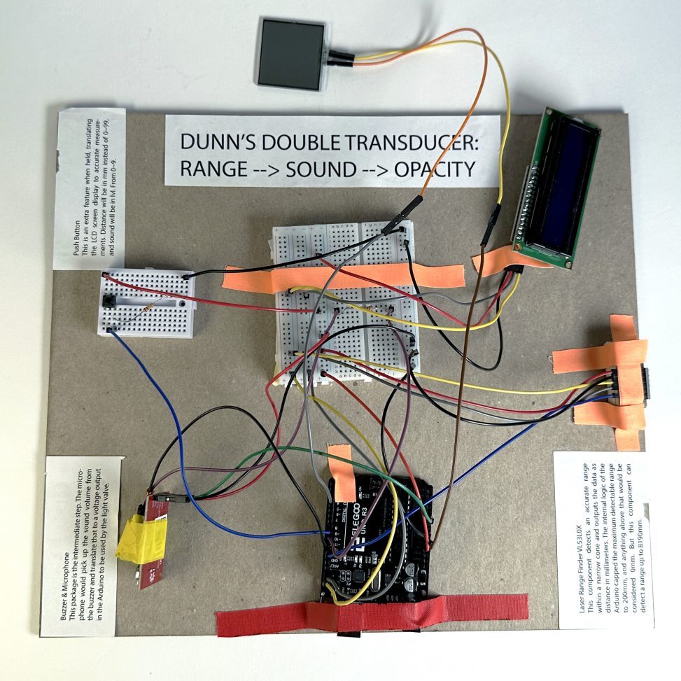
Dunn’s double transducer
(Position -> Sound -> Transparency)
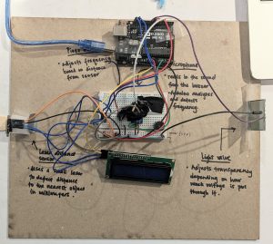
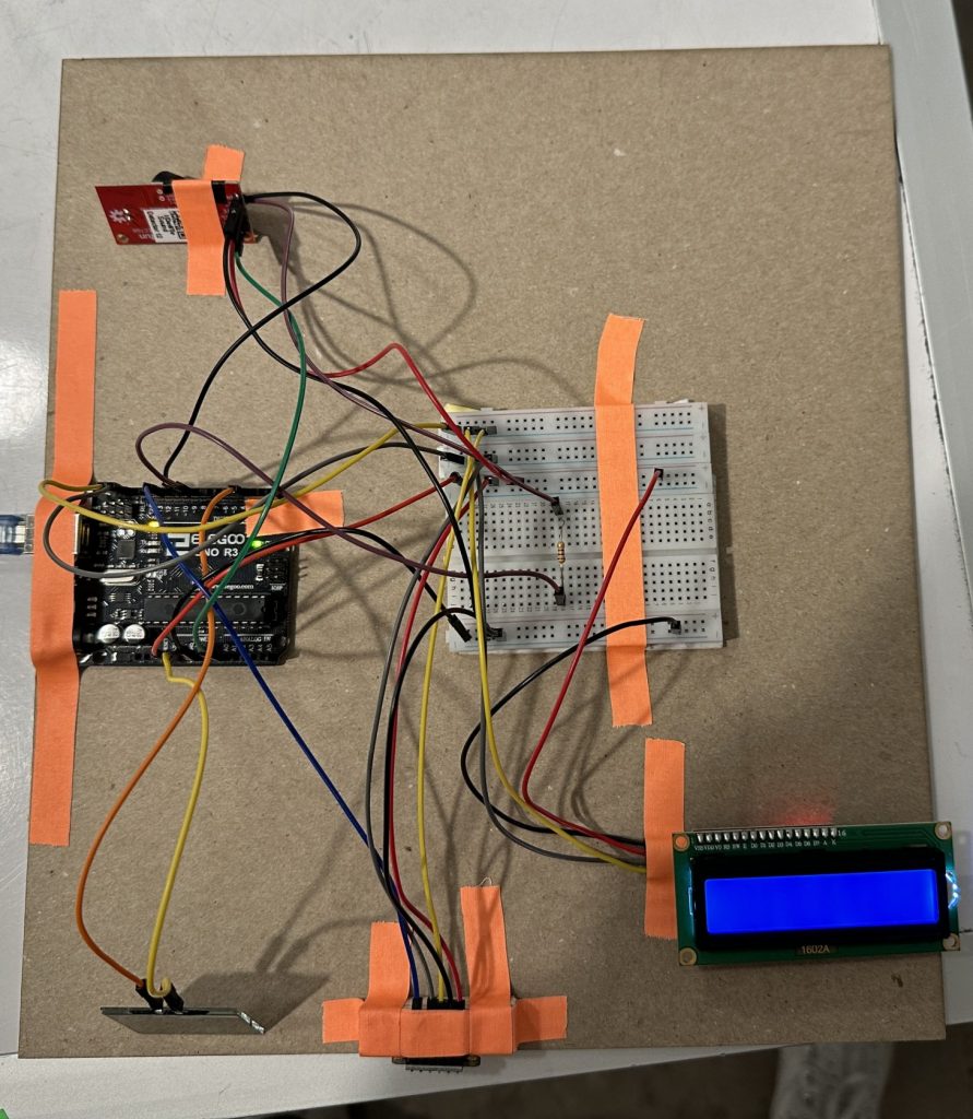
Bhairavi’s Double Transducer (position –> frequency –> transparency)
Part 2. Details
-
-
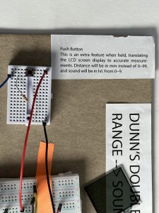
Push Button Extra Feature (Dunn) The push button, when held, will alter the display mode, which converts a mapped value from 0~99 to an accurate representation. For example, when held, the display will show distance in mm.
-
-
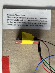
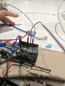
Buzzer & Microphone Combo (Dunn) Picks up the audio output, a tone, from the buzzer and analog write that into the light valve.
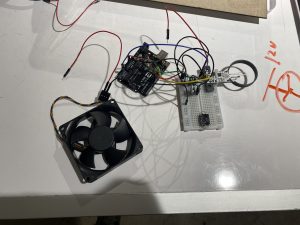
Figuring out how to use a MOSFET for the 12V power needed for the fan. (Mo)
Accidentally plugging the light valve (purple) into a non-PWM pin. (Bhairavi)
Part 3. Demonstration
Dunn’s project in action.
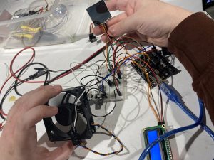
Mo’s project in action.
Bhairavi’s project in action.
Part 4. Narrative
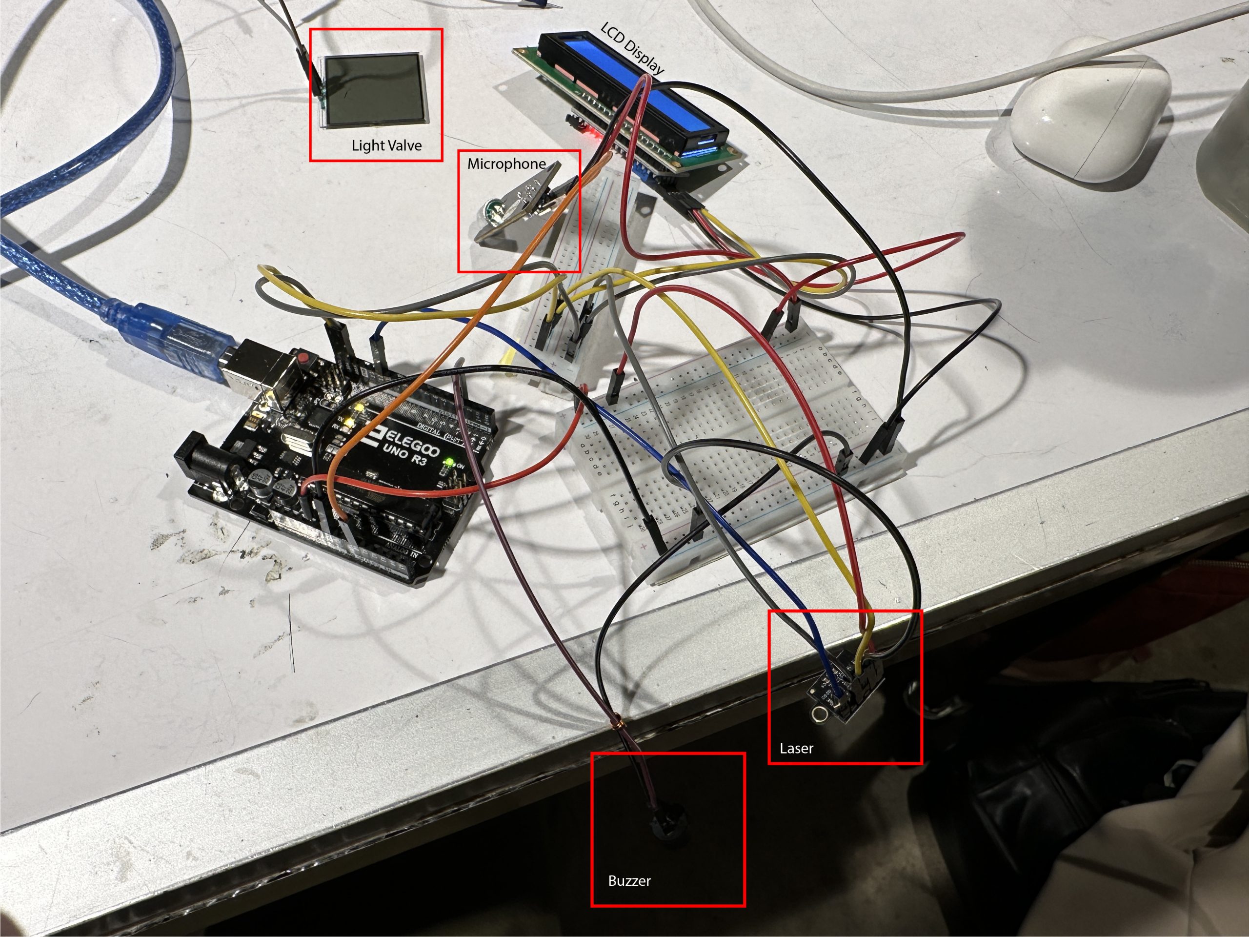
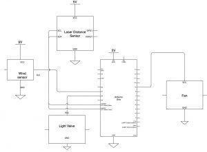
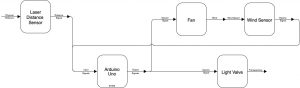
A sensor reads the distance of an object in front of it, then converts that data to transparency through the use of a light valve. Our team had some different approaches to the middle step of the device. Mo used wind speed as the middle step, while Dunn and Bhairavi used sound. Mo’s project uses a fan that blows into a wind sensor for the middle step, while Dunn and Bhairavi’s projects use a buzzer and a microphone.
Part 5. Processes
Dunn’s process:
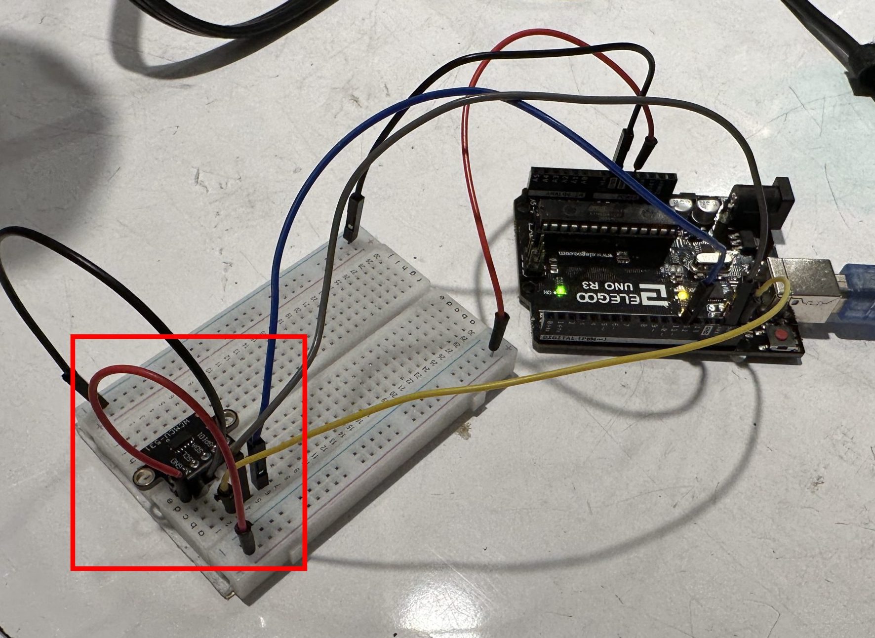
I wanted to ensure the laser was working correctly before proceeding with the other components. The laser range finder required solder before attachment. This component is a much better alternative to the ultrasonic ranger, which has a shorter range and wider scanning cone.
After resolving the laser issue, all other components came together fairly easily and quickly. However, I wanted to ensure everything worked before anchoring the components to the chipboard to avoid potential hardware issues.
Almost-final iteration. Most components are secured in their locations.
Mo’s Process:
-
-
Working on getting the fan to transmit data through the wind sensor to the light valve.
-
-
The beginnings of figuring out how the wiring will work.
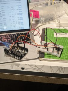
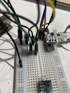
Starting out by individually testing each component. This picture is the laser distance sensor – I found an example sketch on the Adafruit website which I used to learn how the VL530X works. (Bhairavi)
Last thing to change: accidentally plugging the light valve (purple) into a non-PWM pin, meaning that the transparency couldn’t be changed easily. (Bhairavi)
Part 6. Discussion
Overall, this project was an excellent introduction to physical computing: how everything works and comes together. Though our team had different solutions and approaches, they were equally unique and valid. We learned the hard lesson that the product might not work as you intended on the presentation day, and there are always issues to be resolved. It was interesting to see how our teammates approached the project prompt – each of us faced different constraints, leading us to end up with different middle steps for our transducers.
Since there was only one fan present in the classroom, both Dunn and Bhairavi chose to use buzzers generating sound for their middle steps. Dunn chose to control the volume of the buzzer for the middle step, since he found this easier than controlling the frequency. However, Bhairavi had trouble accurately detecting the volume of the buzzer and decided to hone in on the small range of frequencies in which the microphone could detect a linear increase in frequency.
Another difference between our projects was that the sensitivity of the transparency to movement was significantly different. Both Dunn and Bhairavi found it necessary to significantly limit the range in which the laser could detect movement due to range limitations in their middle step, while Mo was able to detect and express a larger range of movement.
Part 7. Functional Block Diagram and Schematic
Part 8. Code Submission
File/Sketch Name: transducer_test
Version No.: v2.0 Created Feb 14 2023 Bhairavi Chandersekhar
Description: This code works to run an Arduino Uno powered double transducer. The transducer converts distance to transparency.
The double transducer uses a VL53L0X 'Time of Flight' Laser distance
sensor to input distance (must be between 40 and 220 mm). The distance signal is then converted by the Arduino to a frequency between
290 and 335 Hz. which is then sent to a passive piezo buzzer. An electret microphone picks up the signal from the passive buzzer and
uses the frequency to control the transparency of a light valve.
Input, intermediate, and output values are displayed on an LCD screen.
- all frequencies between 290 and 355 Hz are not able to be used. Frequencies from 300-315 Hz are very frequently not picked up
accurately by the microphone. This is why much of the code is split up using if statements; frequencies in two different nonadjacent
ranges are generated, and the frequencies picked up are also present in two nonadjacent ranges. Frequencies above, below, or between these
ranges are disregarded as noise.
- Specific ranges in which the microphone is able to detect the frequency accurately depend on the specific choice
of buzzer and microphone, as well as the ambient noise in the room.
5 one lead of the piezo buzzer (other lead to ground)
10 one lead of the light valve (other lead to ground)
A0 electret microphone input
3.3 V runs to electret microphone and laser distance sensor
SCL/SDA connects to both the LCD display and to the laser distance sensor
FFT code based on AudioFrequencyDetector code written by Clyde A. Lettsome, PhD, PE, MEM
For more information visit https://clydelettsome.com/blog/2019/12/18/my-weekend-project-audio-frequency-detector-using-an-arduino/
#include <LiquidCrystal_I2C.h>
#define SAMPLES 128 //SAMPLES-pt FFT. Must be a base 2 number. Max 128 for Arduino Uno.
#define SAMPLING_FREQUENCY 3000 //Ts = Based on Nyquist, must be 2 times the highest expected frequency.
#define PIEZO_PIN 5 // Pin connected to the piezo buzzer.
#define LIGHTVALVE 10 // digital pin connected to the light valve
LiquidCrystal_I2C screen(0x27, 16, 2);
arduinoFFT FFT = arduinoFFT();
unsigned int samplingPeriod;
unsigned long microSeconds;
unsigned long previousMillis;
double vReal[SAMPLES]; //create vector of size SAMPLES to hold real values
double vImag[SAMPLES]; //create vector of size SAMPLES to hold imaginary values
Serial.begin(115200); //Baud rate for the Serial Monitor
samplingPeriod = round(1000000*(1.0/SAMPLING_FREQUENCY)); //Period in microseconds
// TOF distance sensor setup
Serial.println("Failed to detect and initialize sensor!");
// Start continuous back-to-back mode (take readings as
// fast as possible). To use continuous timed mode
// instead, provide a desired inter-measurement period in
// ms (e.g. sensor.startContinuous(100)).
sensor.startContinuous();
previousMillis = millis();
for(int i=0; i<SAMPLES; i++)
microSeconds = micros(); //Returns the number of microseconds since the Arduino board began running the current script.
vReal[i] = analogRead(0); //Reads the value from analog pin 0 (A0), quantize it and save it as a real term.
vImag[i] = 0; //Makes imaginary term 0 always
/*remaining wait time between samples if necessary*/
while(micros() < (microSeconds + samplingPeriod))
/*Perform FFT on samples*/
FFT.Windowing(vReal, SAMPLES, FFT_WIN_TYP_HAMMING, FFT_FORWARD);
FFT.Compute(vReal, vImag, SAMPLES, FFT_FORWARD);
FFT.ComplexToMagnitude(vReal, vImag, SAMPLES);
/*Find peak frequency and print peak*/
double new_peak = FFT.MajorPeak(vReal, SAMPLES, SAMPLING_FREQUENCY);
// print detected frequency to LCD screen.
LCD_peak = map(peak, 865, 955, 0, 17);
LCD_peak = constrain(LCD_peak, 0, 17);
transparency = map(peak, 865, 955, 0, 17);
//transparency = constrain(transparency, 0, 17);
} else if (new_peak > 1190 && new_peak < 1410) {
LCD_peak = map(peak, 1190, 1410, 17, 99);
LCD_peak = constrain(LCD_peak, 17, 99);
transparency = map(peak, 1190, 1410, 17, 99);
//transparency = constrain(transparency, 17, 99);
int LCD_peak = map(peak, 850, 1500, 0, 99);
LCD_peak = constrain(LCD_peak, 0, 99); */
analogWrite(LIGHTVALVE, transparency);
int LCD_transparency = map(transparency, 0, 120, 0, 99);
LCD_transparency = constrain(LCD_transparency, 0, 99);
Serial.print("peak frequency: ");
Serial.println(peak); //Print out the most dominant frequency.
Serial.print("transparency: ");
Serial.println(transparency);
int distance = sensor.readRangeContinuousMillimeters();
// map distance from 0-100
long LCD_distance = map(distance, 40, 210, 0, 99);
LCD_distance = constrain(LCD_distance, 0, 99);
screen.print(LCD_distance);
//calculate piezo freq. based on distance
frequency = map(distance, 40, 85, 290, 295);
frequency = constrain(frequency, 290, 295);
frequency = map(distance, 85, 220, 315, 335);
frequency = constrain(frequency, 315, 335);
tone(PIEZO_PIN, frequency);
//print to LCD screen, column 6 row 0
// map frequency from 0 - 99;
LCD_frequency = map(frequency, 290, 295, 0, 17);
LCD_frequency = constrain(LCD_frequency, 0, 17);
LCD_frequency = map(frequency, 315, 335, 17, 99);
LCD_frequency = constrain(LCD_frequency, 17, 99);
screen.print(LCD_frequency);
if (sensor.timeoutOccurred()) { Serial.print(" TIMEOUT"); }
// first generate a sound
// then read in the frequency
// refresh the screen every half a second.
unsigned long currentMillis = millis();
if (currentMillis - previousMillis > 500) {
previousMillis = currentMillis;
/*
 File/Sketch Name: transducer_test

 Version No.: v2.0 Created Feb 14 2023 Bhairavi Chandersekhar

 Description:  This code works to run an Arduino Uno powered double transducer. The transducer converts distance to transparency.
 The double transducer uses a VL53L0X 'Time of Flight' Laser distance
 sensor to input distance (must be between 40 and 220 mm). The distance signal is then converted by the Arduino to a frequency between
 290 and 335 Hz. which is then sent to a passive piezo buzzer. An electret microphone picks up the signal from the passive buzzer and
 uses the frequency to control the transparency of a light valve.
 Input, intermediate, and output values are displayed on an LCD screen.

 Notes:
 - all frequencies between 290 and 355 Hz are not able to be used. Frequencies from 300-315 Hz are very frequently not picked up
 accurately by the microphone. This is why much of the code is split up using if statements; frequencies in two different nonadjacent
 ranges are generated, and the frequencies picked up are also present in two nonadjacent ranges. Frequencies above, below, or between these
 ranges are disregarded as noise.
 - Specific ranges in which the microphone is able to detect the frequency accurately depend on the specific choice
 of buzzer and microphone, as well as the ambient noise in the room.

 Pin Mappings:
 5        one lead of the piezo buzzer (other lead to ground)
 10       one lead of the light valve (other lead to ground)
 A0       electret microphone input
 3.3 V    runs to electret microphone and laser distance sensor
 5V       runs to LCD display.
 SCL/SDA  connects to both the LCD display and to the laser distance sensor


 FFT code based on AudioFrequencyDetector code written by Clyde A. Lettsome, PhD, PE, MEM
 For more information visit https://clydelettsome.com/blog/2019/12/18/my-weekend-project-audio-frequency-detector-using-an-arduino/

*/

#include "arduinoFFT.h"
#include <Wire.h>
#include <VL53L0X.h>
#include <LiquidCrystal_I2C.h>

#define SAMPLES 128             //SAMPLES-pt FFT. Must be a base 2 number. Max 128 for Arduino Uno.
#define SAMPLING_FREQUENCY 3000 //Ts = Based on Nyquist, must be 2 times the highest expected frequency.
#define PIEZO_PIN  5      // Pin connected to the piezo buzzer.
#define LIGHTVALVE 10             // digital pin connected to the light valve

VL53L0X sensor;
LiquidCrystal_I2C screen(0x27, 16, 2);
arduinoFFT FFT = arduinoFFT();

unsigned int samplingPeriod;
unsigned long microSeconds;
unsigned long previousMillis;

double vReal[SAMPLES]; //create vector of size SAMPLES to hold real values
double vImag[SAMPLES]; //create vector of size SAMPLES to hold imaginary values

int peak;
int LCD_peak;

void setup()
{
  // FFT setup
  Serial.begin(115200); //Baud rate for the Serial Monitor
  samplingPeriod = round(1000000*(1.0/SAMPLING_FREQUENCY)); //Period in microseconds

  // TOF distance sensor setup
  delay(100);
  Wire.begin();

  screen.init();
  screen.backlight();
  screen.home();

  sensor.setTimeout(500);
  if (!sensor.init())
  {
    Serial.println("Failed to detect and initialize sensor!");
    while (1) {}
  }
  // Start continuous back-to-back mode (take readings as
  // fast as possible).  To use continuous timed mode
  // instead, provide a desired inter-measurement period in
  // ms (e.g. sensor.startContinuous(100)).
  sensor.startContinuous();

  previousMillis = millis();

  peak = 0;
  LCD_peak = 0;

}

double fft()
{
  /*Sample SAMPLES times*/
    for(int i=0; i<SAMPLES; i++)
    {
        microSeconds = micros();    //Returns the number of microseconds since the Arduino board began running the current script.

        vReal[i] = analogRead(0); //Reads the value from analog pin 0 (A0), quantize it and save it as a real term.
        vImag[i] = 0; //Makes imaginary term 0 always

        /*remaining wait time between samples if necessary*/
        while(micros() < (microSeconds + samplingPeriod))
        {
          //do nothing
        }
    }

    /*Perform FFT on samples*/
    FFT.Windowing(vReal, SAMPLES, FFT_WIN_TYP_HAMMING, FFT_FORWARD);
    FFT.Compute(vReal, vImag, SAMPLES, FFT_FORWARD);
    FFT.ComplexToMagnitude(vReal, vImag, SAMPLES);

    /*Find peak frequency and print peak*/
    double new_peak = FFT.MajorPeak(vReal, SAMPLES, SAMPLING_FREQUENCY);
    long transparency;

    // print detected frequency to LCD screen.
    if (new_peak < 1000) {
      peak = new_peak;
      LCD_peak = map(peak, 865, 955, 0, 17);
      LCD_peak = constrain(LCD_peak, 0, 17);
      transparency = map(peak, 865, 955, 0, 17);
      //transparency = constrain(transparency, 0, 17);
    } else if (new_peak > 1190 && new_peak < 1410) {
      peak = new_peak;
      LCD_peak = map(peak, 1190, 1410, 17, 99);
      LCD_peak = constrain(LCD_peak, 17, 99);
      transparency = map(peak, 1190, 1410, 17, 99);
      //transparency = constrain(transparency, 17, 99);
    }
    /*
    int LCD_peak = map(peak, 850, 1500, 0, 99);
    LCD_peak = constrain(LCD_peak, 0, 99); */
    screen.setCursor(6, 1);
    screen.print(LCD_peak);
    if (transparency < 0) {
      transparency = 0;
    }
    analogWrite(LIGHTVALVE, transparency);

    int LCD_transparency = map(transparency, 0, 120, 0, 99);
    LCD_transparency = constrain(LCD_transparency, 0, 99);
    screen.setCursor(12, 1);
    screen.print(LCD_peak);
    Serial.print("peak frequency: ");
    Serial.println(peak);     //Print out the most dominant frequency.
    Serial.print("transparency: ");
    Serial.println(transparency);
}

void buzz()
{
  // detect distance
  int distance = sensor.readRangeContinuousMillimeters();

  // print to LCD screen
  screen.home();
  screen.print("i:");
  // map distance from 0-100
  long LCD_distance = map(distance, 40, 210, 0, 99);
  LCD_distance = constrain(LCD_distance, 0, 99);
  screen.print(LCD_distance);


  //calculate piezo freq. based on distance
  int frequency;
  if (distance < 85) {
    frequency = map(distance, 40, 85, 290, 295);
    frequency = constrain(frequency, 290, 295);
  } else {
    frequency = map(distance, 85, 220, 315, 335);
    frequency = constrain(frequency, 315, 335);
  }
  tone(PIEZO_PIN, frequency);

  //print to LCD screen, column 6 row 0
  screen.setCursor(6, 0);
  screen.print("m:");

  // map frequency from 0 - 99;
  int LCD_frequency;
  if (frequency <= 295) {
    LCD_frequency = map(frequency, 290, 295, 0, 17);
    LCD_frequency = constrain(LCD_frequency, 0, 17);
  } else {
    LCD_frequency = map(frequency, 315, 335, 17, 99);
    LCD_frequency = constrain(LCD_frequency, 17, 99);
  }
  screen.print(LCD_frequency);
  if (sensor.timeoutOccurred()) { Serial.print(" TIMEOUT"); }
}
void loop()
{
  // first generate a sound
  buzz();
  // then read in the frequency
  fft();

  // refresh the screen every half a second.
  unsigned long currentMillis = millis();
  if (currentMillis - previousMillis > 500) {
    screen.clear();
    previousMillis = currentMillis;
  }
}
/*
File/Sketch Name: transducer_test
Version No.: v2.0 Created Feb 14 2023 Bhairavi Chandersekhar
Description: This code works to run an Arduino Uno powered double transducer. The transducer converts distance to transparency.
The double transducer uses a VL53L0X 'Time of Flight' Laser distance
sensor to input distance (must be between 40 and 220 mm). The distance signal is then converted by the Arduino to a frequency between
290 and 335 Hz. which is then sent to a passive piezo buzzer. An electret microphone picks up the signal from the passive buzzer and
uses the frequency to control the transparency of a light valve.
Input, intermediate, and output values are displayed on an LCD screen.
Notes:
- all frequencies between 290 and 355 Hz are not able to be used. Frequencies from 300-315 Hz are very frequently not picked up
accurately by the microphone. This is why much of the code is split up using if statements; frequencies in two different nonadjacent
ranges are generated, and the frequencies picked up are also present in two nonadjacent ranges. Frequencies above, below, or between these
ranges are disregarded as noise.
- Specific ranges in which the microphone is able to detect the frequency accurately depend on the specific choice
of buzzer and microphone, as well as the ambient noise in the room.
Pin Mappings:
5 one lead of the piezo buzzer (other lead to ground)
10 one lead of the light valve (other lead to ground)
A0 electret microphone input
3.3 V runs to electret microphone and laser distance sensor
5V runs to LCD display.
SCL/SDA connects to both the LCD display and to the laser distance sensor
FFT code based on AudioFrequencyDetector code written by Clyde A. Lettsome, PhD, PE, MEM
For more information visit https://clydelettsome.com/blog/2019/12/18/my-weekend-project-audio-frequency-detector-using-an-arduino/
*/
#include "arduinoFFT.h"
#include <Wire.h>
#include <VL53L0X.h>
#include <LiquidCrystal_I2C.h>
#define SAMPLES 128 //SAMPLES-pt FFT. Must be a base 2 number. Max 128 for Arduino Uno.
#define SAMPLING_FREQUENCY 3000 //Ts = Based on Nyquist, must be 2 times the highest expected frequency.
#define PIEZO_PIN 5 // Pin connected to the piezo buzzer.
#define LIGHTVALVE 10 // digital pin connected to the light valve
VL53L0X sensor;
LiquidCrystal_I2C screen(0x27, 16, 2);
arduinoFFT FFT = arduinoFFT();
unsigned int samplingPeriod;
unsigned long microSeconds;
unsigned long previousMillis;
double vReal[SAMPLES]; //create vector of size SAMPLES to hold real values
double vImag[SAMPLES]; //create vector of size SAMPLES to hold imaginary values
int peak;
int LCD_peak;
void setup()
{
// FFT setup
Serial.begin(115200); //Baud rate for the Serial Monitor
samplingPeriod = round(1000000*(1.0/SAMPLING_FREQUENCY)); //Period in microseconds
// TOF distance sensor setup
delay(100);
Wire.begin();
screen.init();
screen.backlight();
screen.home();
sensor.setTimeout(500);
if (!sensor.init())
{
Serial.println("Failed to detect and initialize sensor!");
while (1) {}
}
// Start continuous back-to-back mode (take readings as
// fast as possible). To use continuous timed mode
// instead, provide a desired inter-measurement period in
// ms (e.g. sensor.startContinuous(100)).
sensor.startContinuous();
previousMillis = millis();
peak = 0;
LCD_peak = 0;
}
double fft()
{
/*Sample SAMPLES times*/
for(int i=0; i<SAMPLES; i++)
{
microSeconds = micros(); //Returns the number of microseconds since the Arduino board began running the current script.
vReal[i] = analogRead(0); //Reads the value from analog pin 0 (A0), quantize it and save it as a real term.
vImag[i] = 0; //Makes imaginary term 0 always
/*remaining wait time between samples if necessary*/
while(micros() < (microSeconds + samplingPeriod))
{
//do nothing
}
}
/*Perform FFT on samples*/
FFT.Windowing(vReal, SAMPLES, FFT_WIN_TYP_HAMMING, FFT_FORWARD);
FFT.Compute(vReal, vImag, SAMPLES, FFT_FORWARD);
FFT.ComplexToMagnitude(vReal, vImag, SAMPLES);
/*Find peak frequency and print peak*/
double new_peak = FFT.MajorPeak(vReal, SAMPLES, SAMPLING_FREQUENCY);
long transparency;
// print detected frequency to LCD screen.
if (new_peak < 1000) {
peak = new_peak;
LCD_peak = map(peak, 865, 955, 0, 17);
LCD_peak = constrain(LCD_peak, 0, 17);
transparency = map(peak, 865, 955, 0, 17);
//transparency = constrain(transparency, 0, 17);
} else if (new_peak > 1190 && new_peak < 1410) {
peak = new_peak;
LCD_peak = map(peak, 1190, 1410, 17, 99);
LCD_peak = constrain(LCD_peak, 17, 99);
transparency = map(peak, 1190, 1410, 17, 99);
//transparency = constrain(transparency, 17, 99);
}
/*
int LCD_peak = map(peak, 850, 1500, 0, 99);
LCD_peak = constrain(LCD_peak, 0, 99); */
screen.setCursor(6, 1);
screen.print(LCD_peak);
if (transparency < 0) {
transparency = 0;
}
analogWrite(LIGHTVALVE, transparency);
int LCD_transparency = map(transparency, 0, 120, 0, 99);
LCD_transparency = constrain(LCD_transparency, 0, 99);
screen.setCursor(12, 1);
screen.print(LCD_peak);
Serial.print("peak frequency: ");
Serial.println(peak); //Print out the most dominant frequency.
Serial.print("transparency: ");
Serial.println(transparency);
}
void buzz()
{
// detect distance
int distance = sensor.readRangeContinuousMillimeters();
// print to LCD screen
screen.home();
screen.print("i:");
// map distance from 0-100
long LCD_distance = map(distance, 40, 210, 0, 99);
LCD_distance = constrain(LCD_distance, 0, 99);
screen.print(LCD_distance);
//calculate piezo freq. based on distance
int frequency;
if (distance < 85) {
frequency = map(distance, 40, 85, 290, 295);
frequency = constrain(frequency, 290, 295);
} else {
frequency = map(distance, 85, 220, 315, 335);
frequency = constrain(frequency, 315, 335);
}
tone(PIEZO_PIN, frequency);
//print to LCD screen, column 6 row 0
screen.setCursor(6, 0);
screen.print("m:");
// map frequency from 0 - 99;
int LCD_frequency;
if (frequency <= 295) {
LCD_frequency = map(frequency, 290, 295, 0, 17);
LCD_frequency = constrain(LCD_frequency, 0, 17);
} else {
LCD_frequency = map(frequency, 315, 335, 17, 99);
LCD_frequency = constrain(LCD_frequency, 17, 99);
}
screen.print(LCD_frequency);
if (sensor.timeoutOccurred()) { Serial.print(" TIMEOUT"); }
}
void loop()
{
// first generate a sound
buzz();
// then read in the frequency
fft();
// refresh the screen every half a second.
unsigned long currentMillis = millis();
if (currentMillis - previousMillis > 500) {
screen.clear();
previousMillis = currentMillis;
}
}