
Full View:
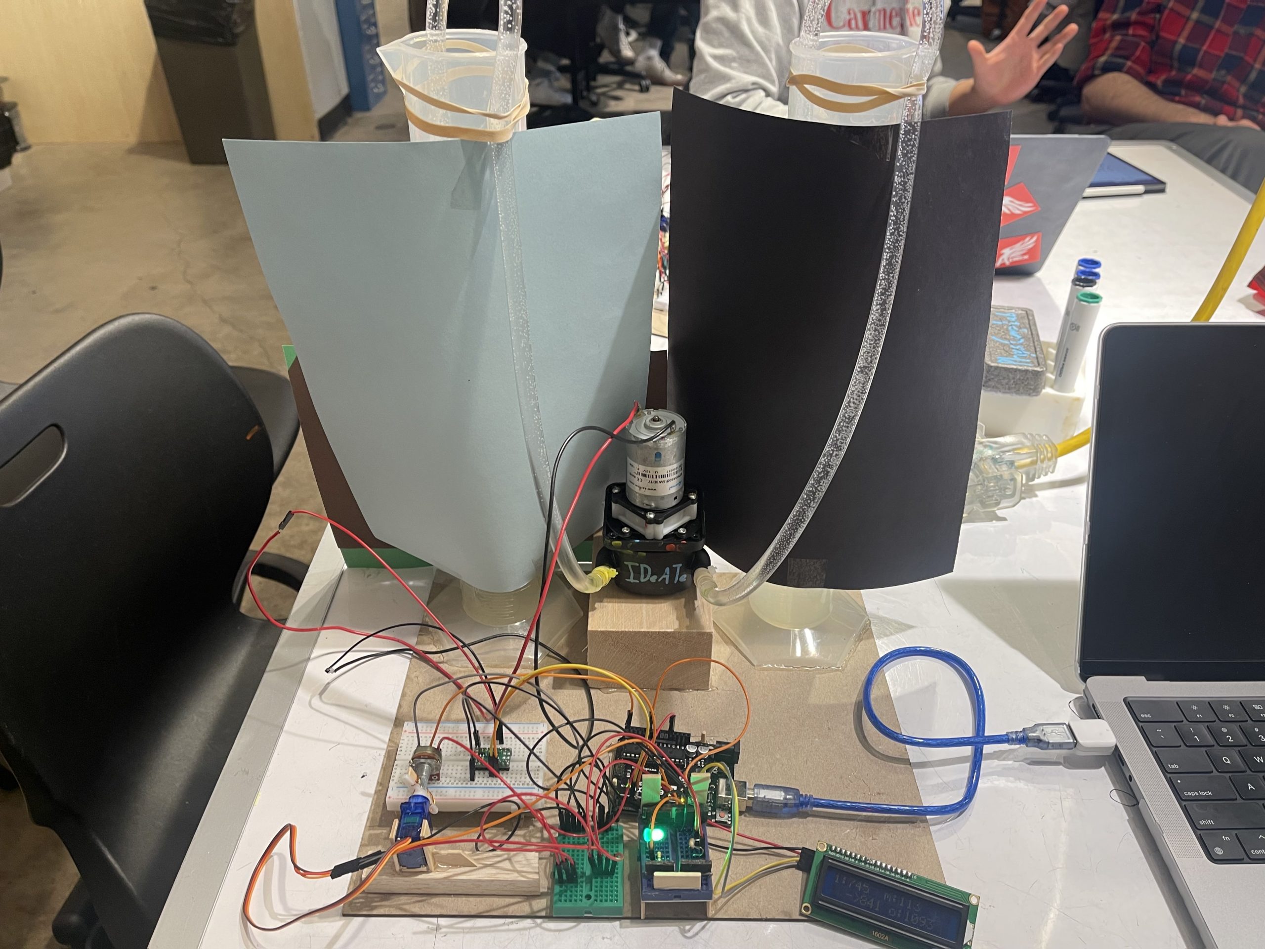
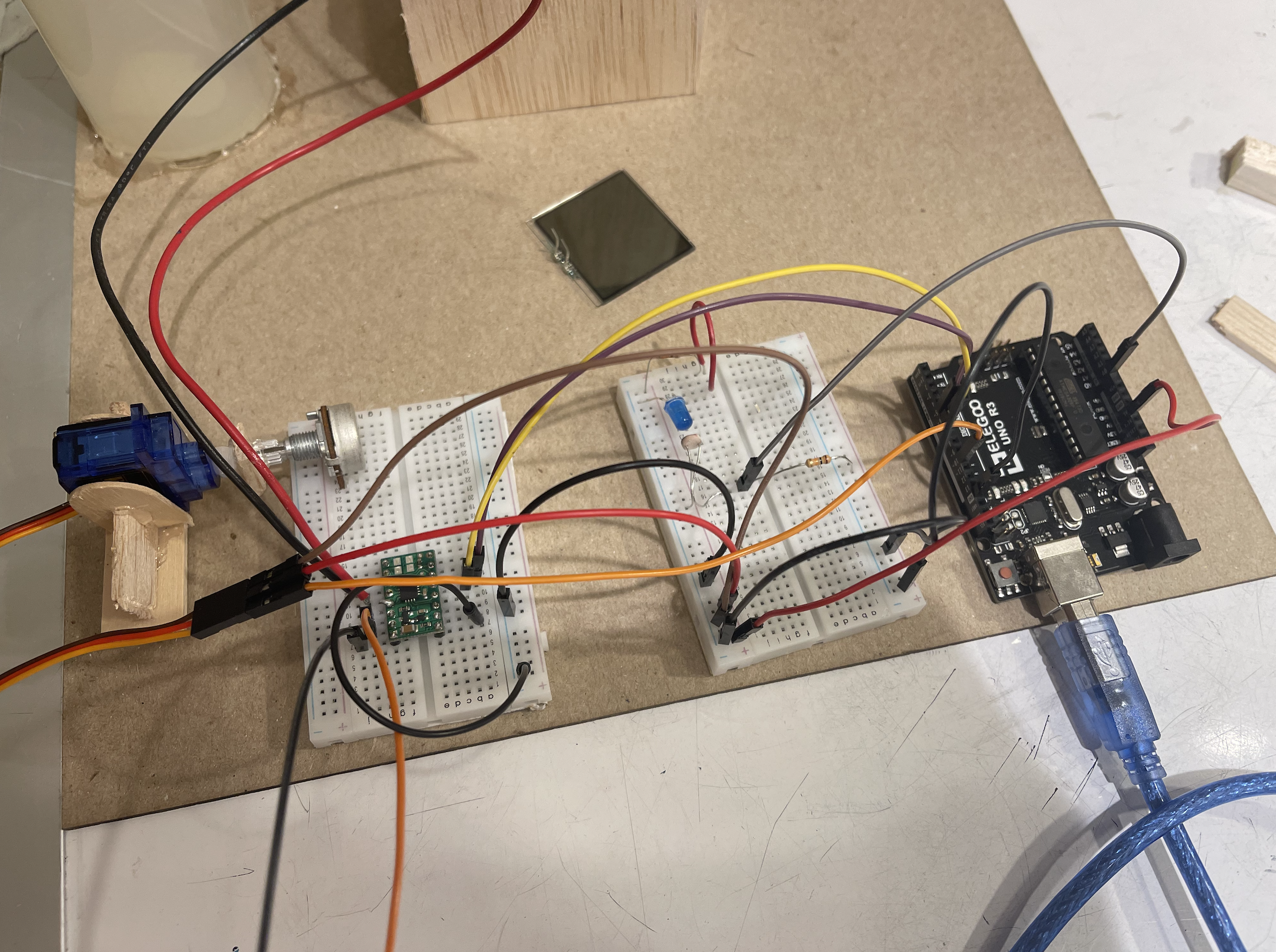
Overall top-level view of project
Yuxi
Overall view of the project
~~~
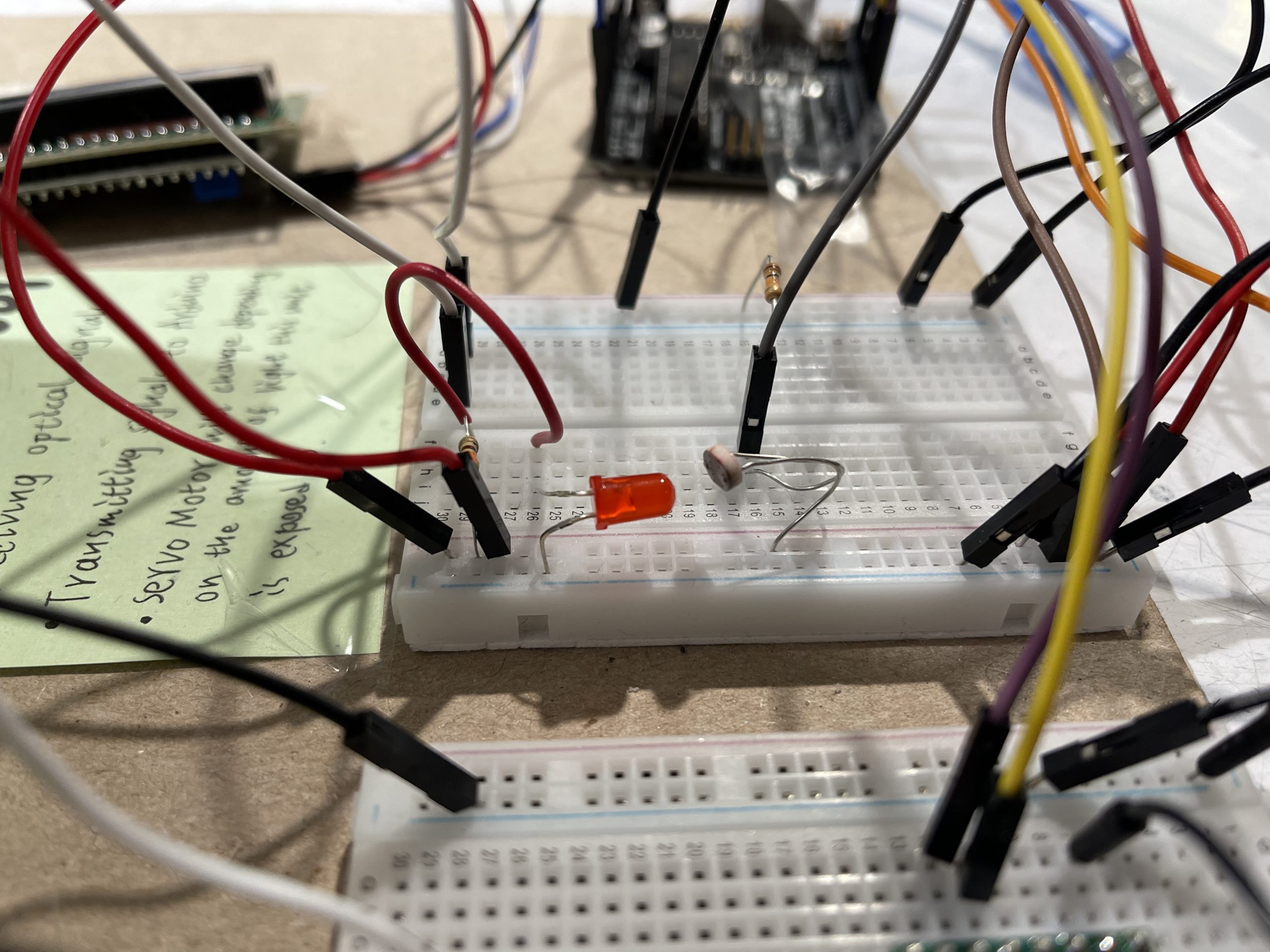
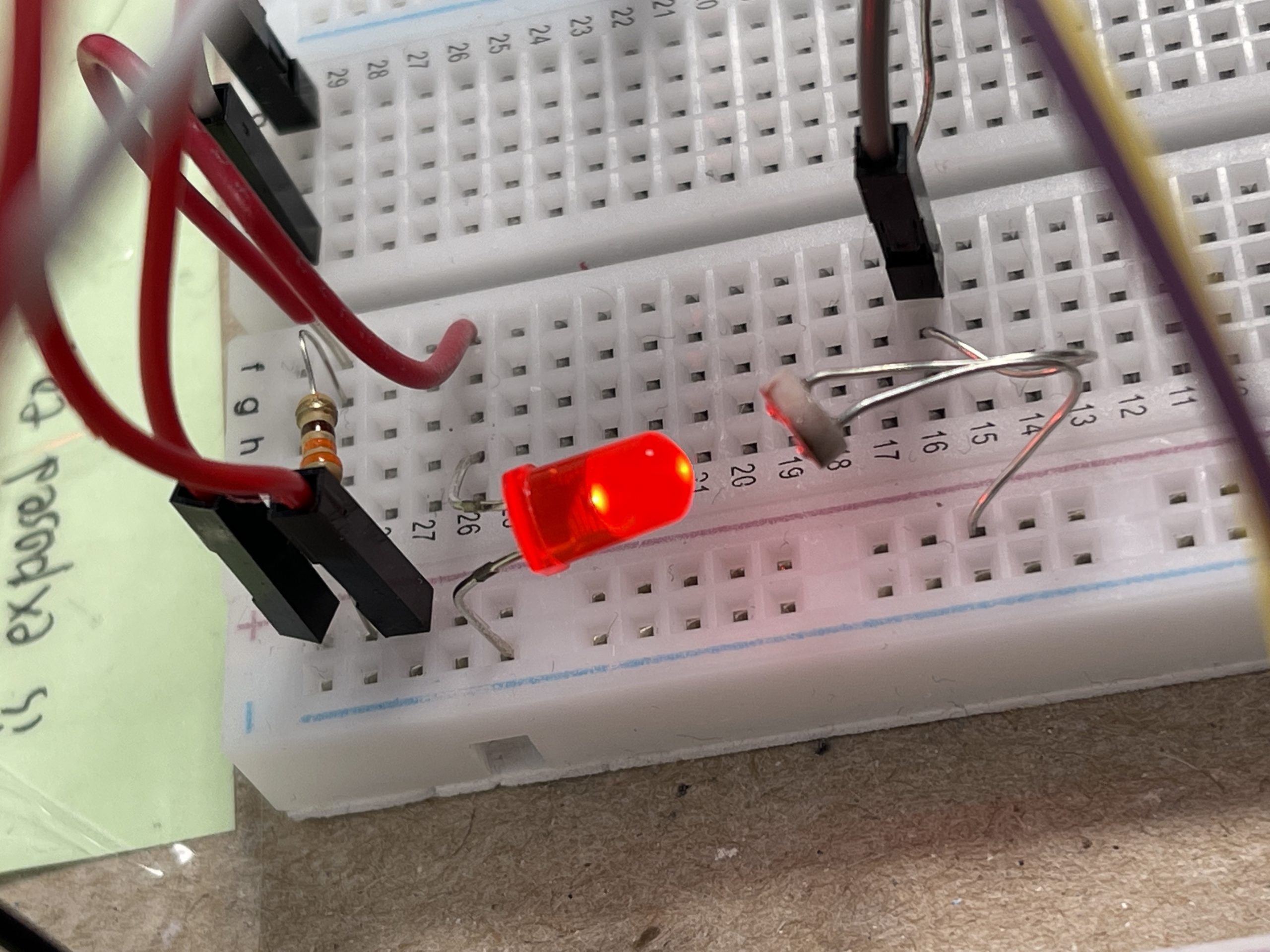
Transparency station:
Light valve is inserted between LED and photo-resistor
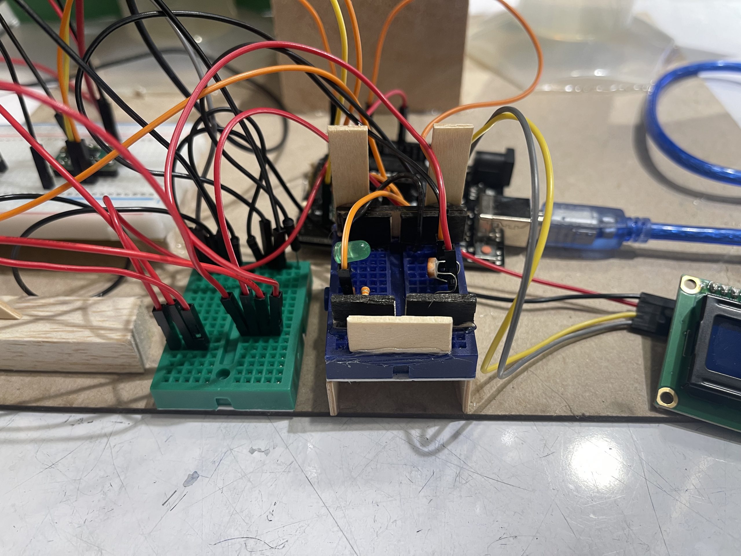
LED (off)
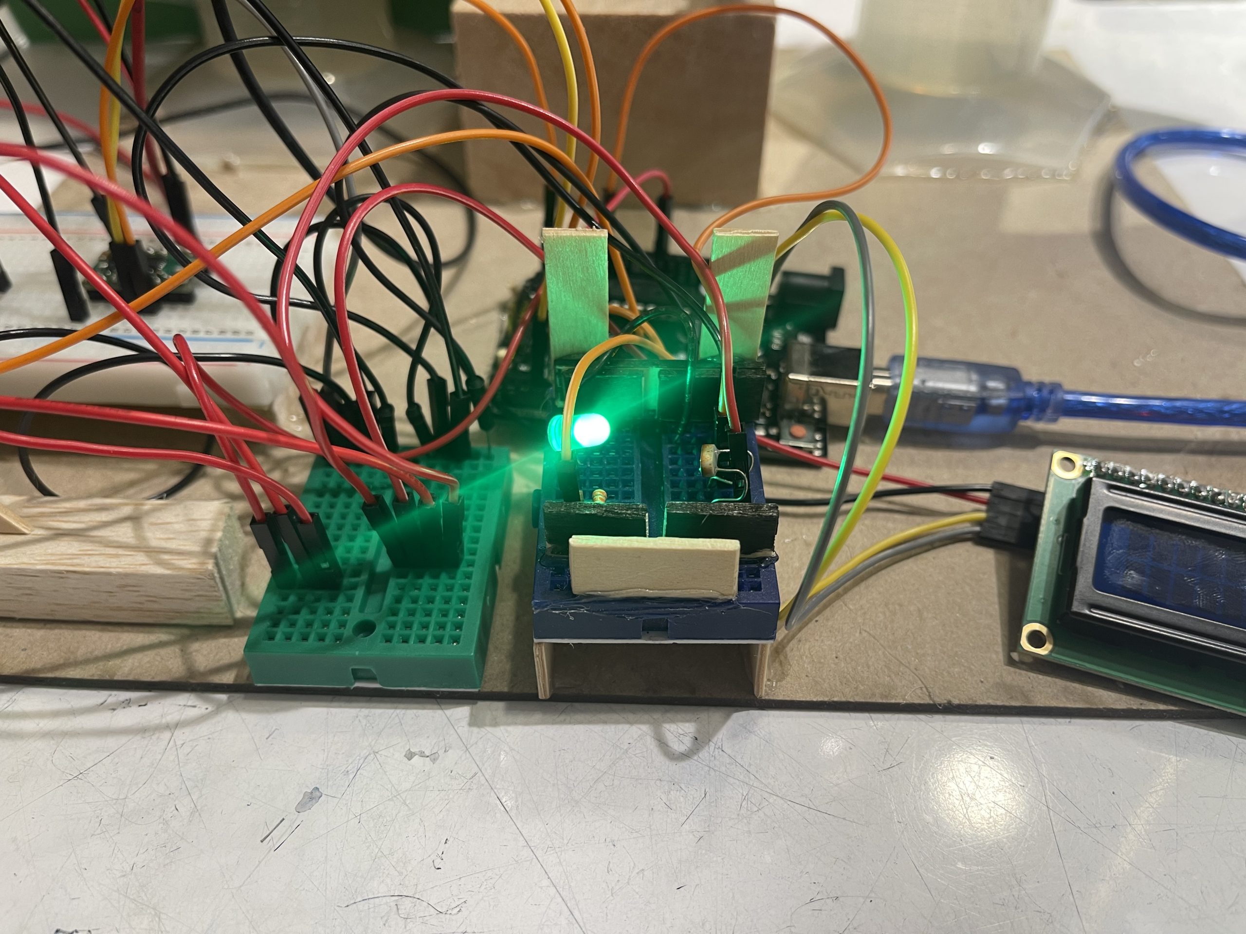
LED (on)
Yuxi
LED OFF
LED ON
~~~
Servo -> Potentiometer:
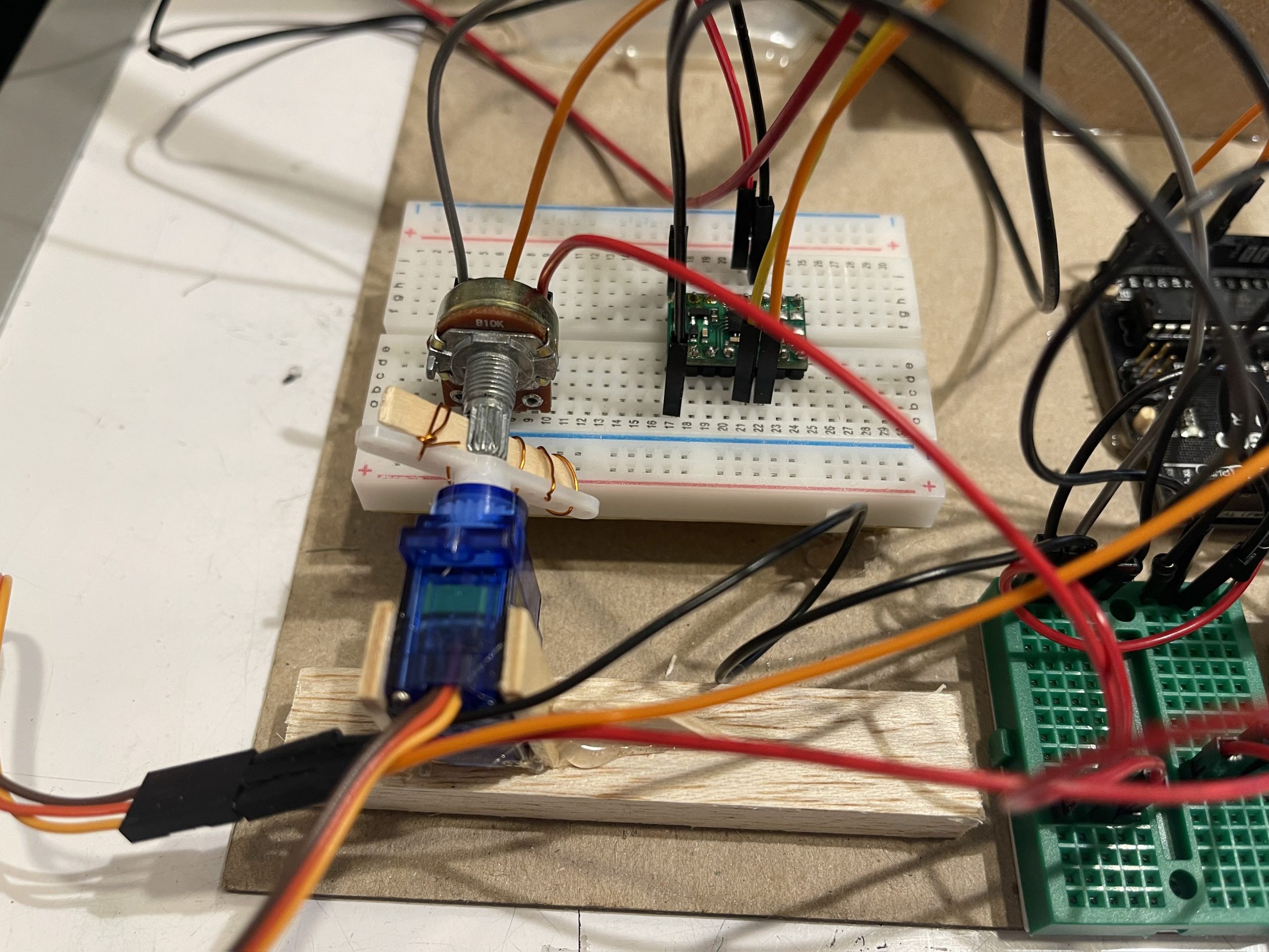
Servo motor attached to potentiometer
Yuxi
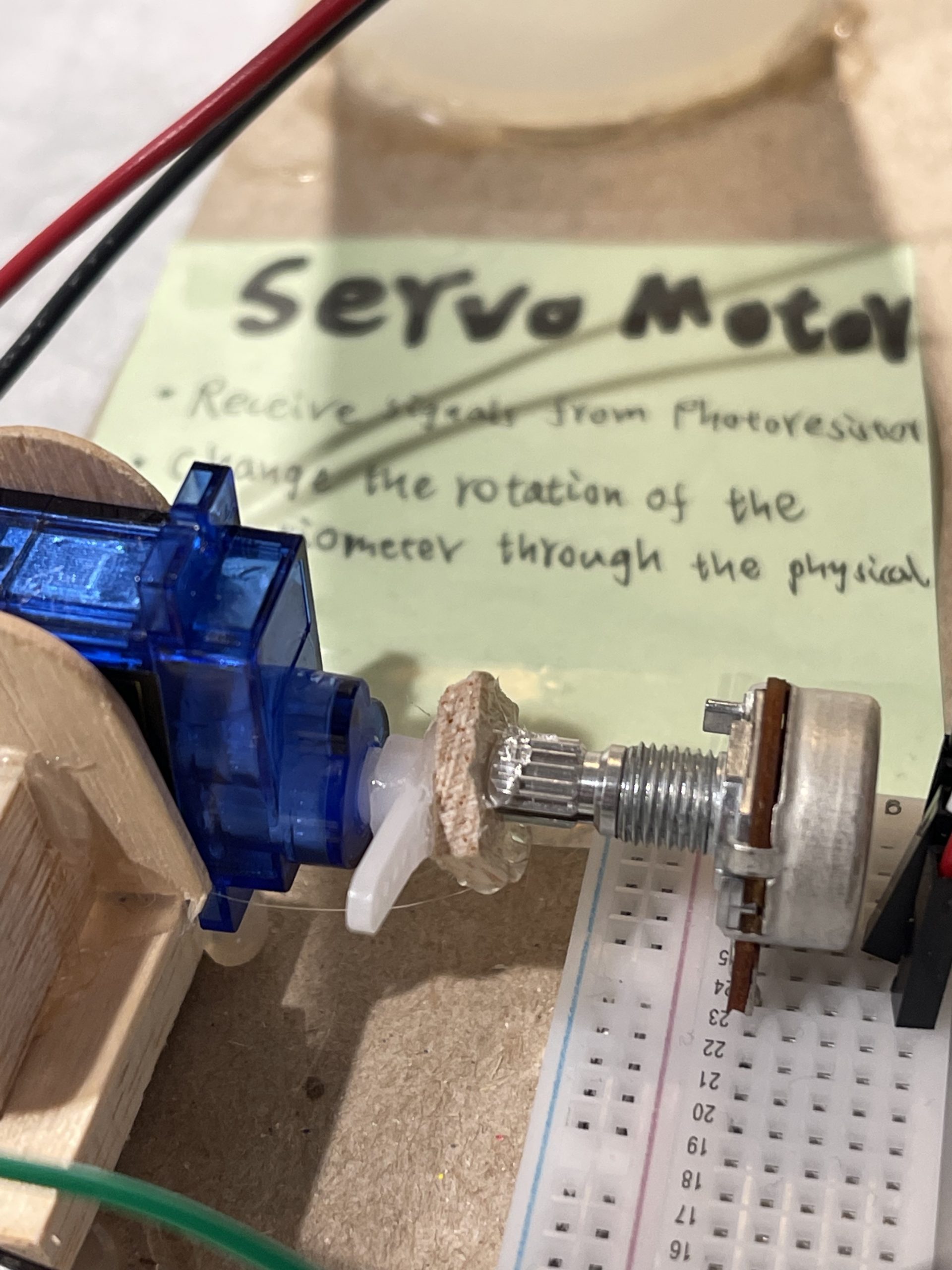
Servo motor physically connected to the potentiometer (by hot glue)
~~~
Video Demo:
Simple Narrative:
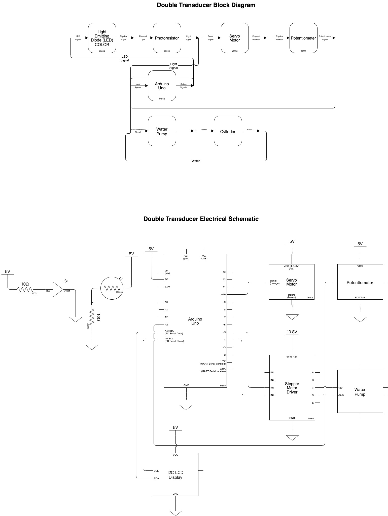
A square that can change its transparency called a light valve is placed between the LED and photo-resistor. This triggers the servo motor (blue motor on the right) to twist which in turn twists the potentiometer. This triggers the pump to vary the water level in the cylinders.
Simple Narrative:
The photoresistor receives the light signal from the LED, which triggers the rotation of the blue servo motor, which physically controls the rotation of the potentiometer and eventually triggers the water pump to change the water level.
—
Mid-process Photos:
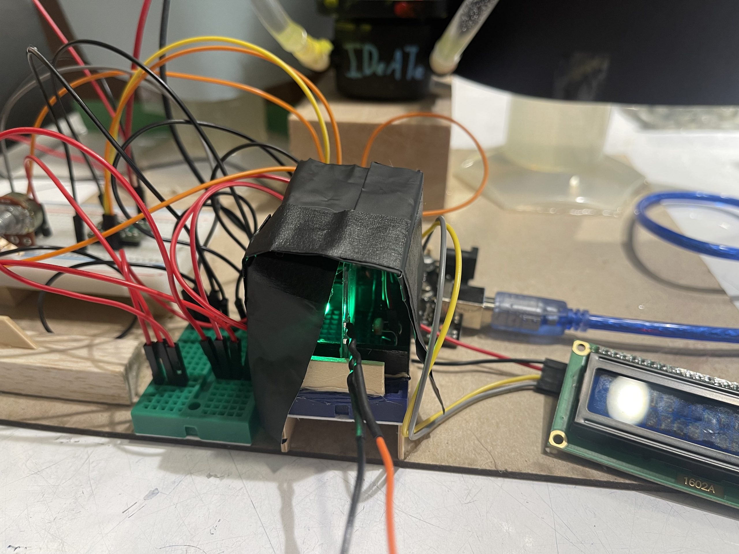
Custom dark room cover for transparency station in order to get more accurate readings of the light valve.
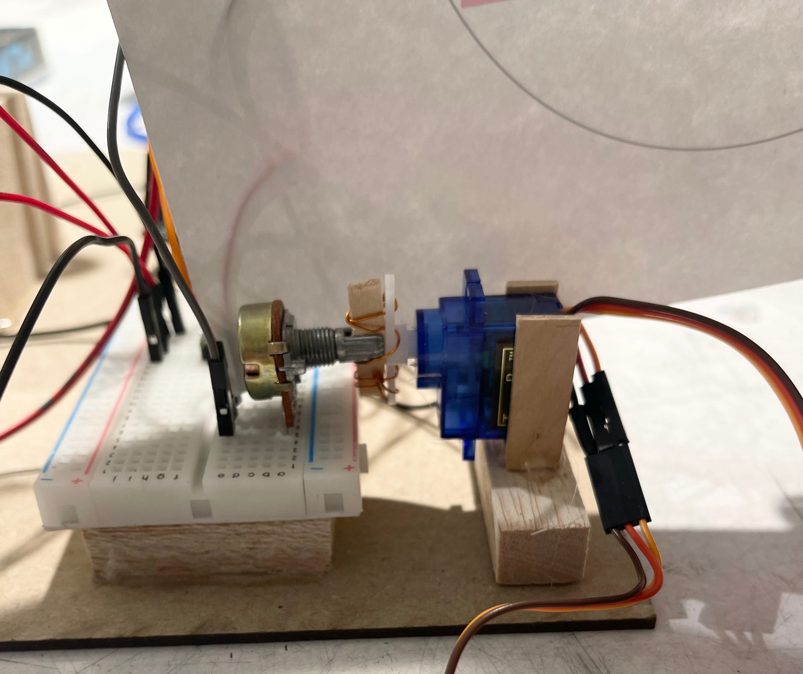
We chose to attach the servo motor with the potentiometer by inserting a popsicle stick in the potentiometer knob and then wrapping wire around the servo arm and the stick.
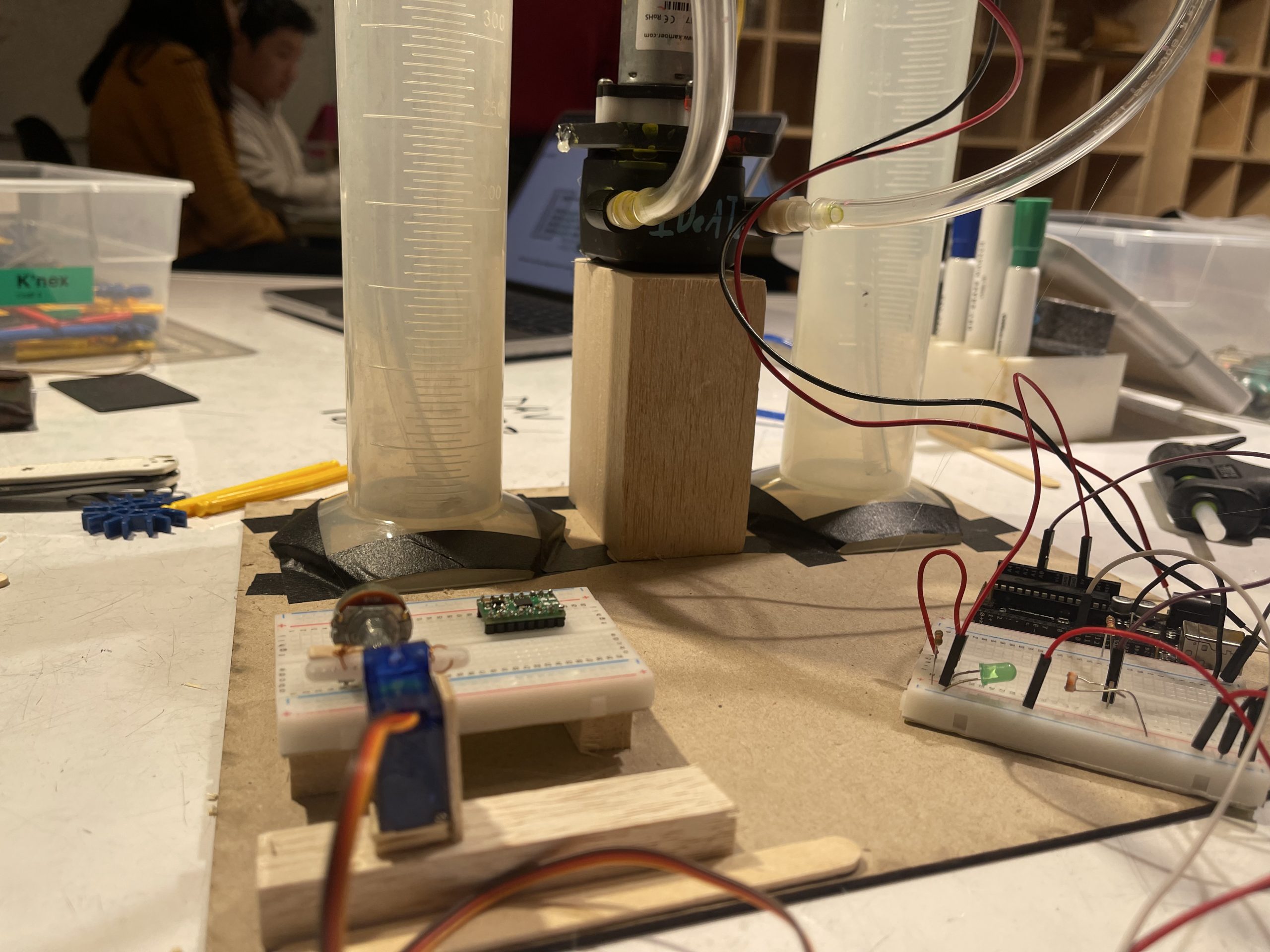
Initial basic layout of all components of the double transducer.
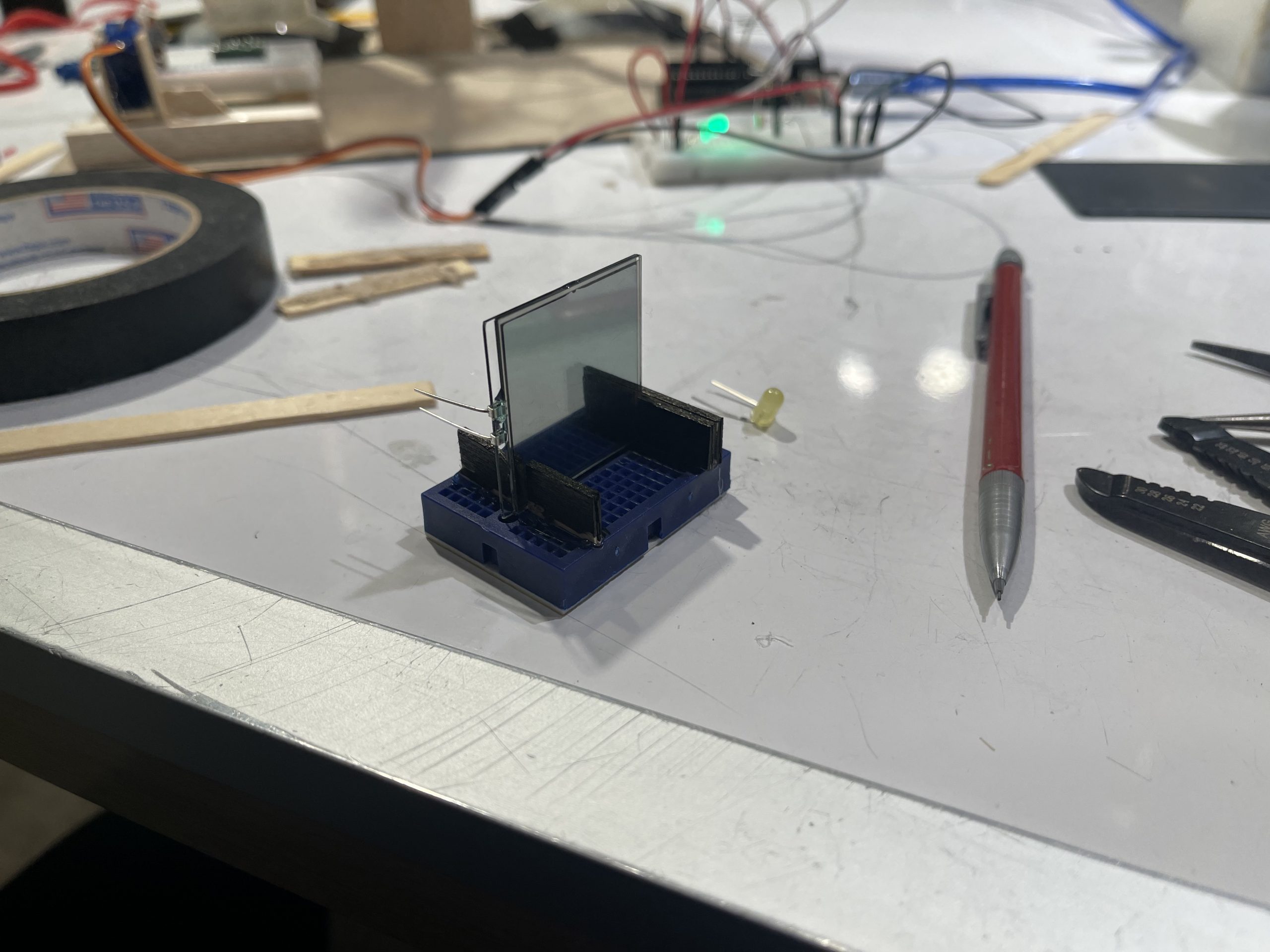
Custom slot for light valve for other team to easily insert their light valve into our station.
Yuxi
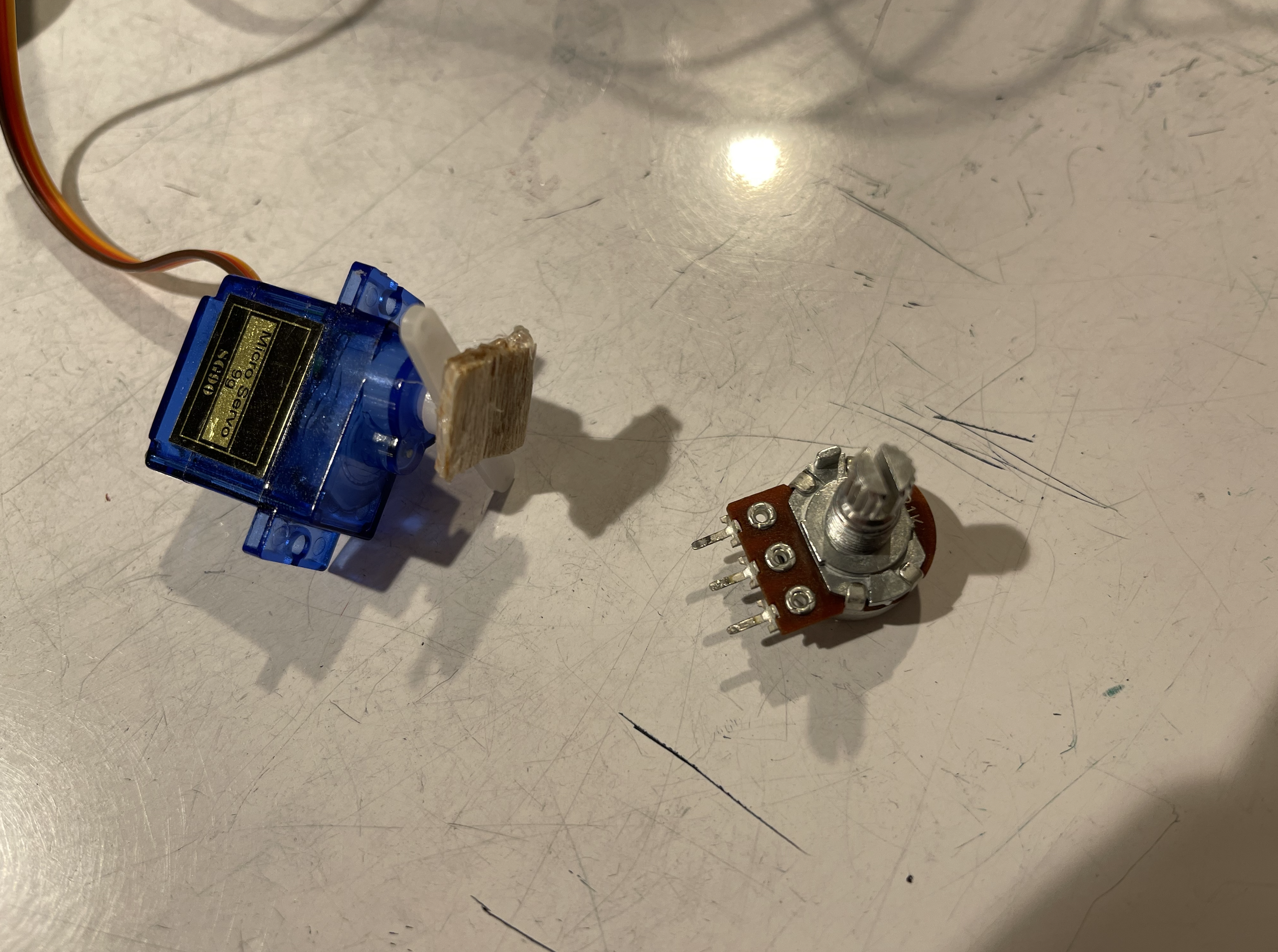
We try to connect servo motor and potentiometer directly with hot glue by a simpler method.
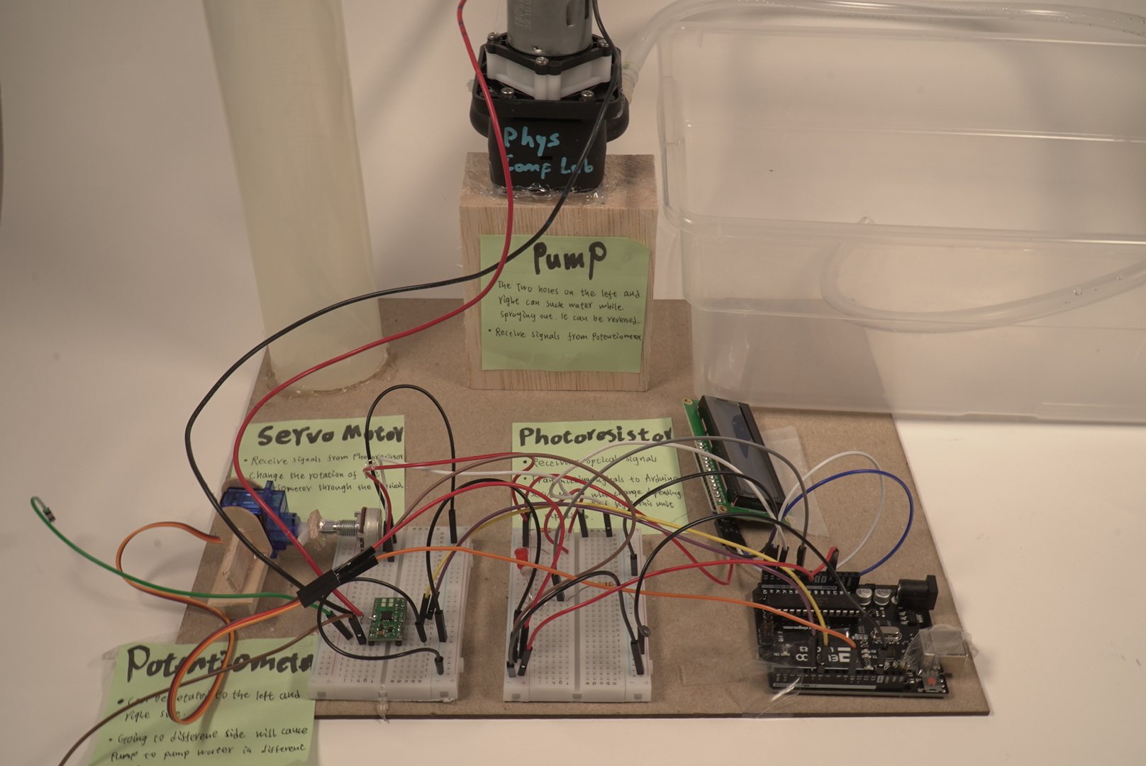
We solved the problem of how to connect the pump to the Arduino Uno. The key is that we need a motor driver and how we need to connect it.
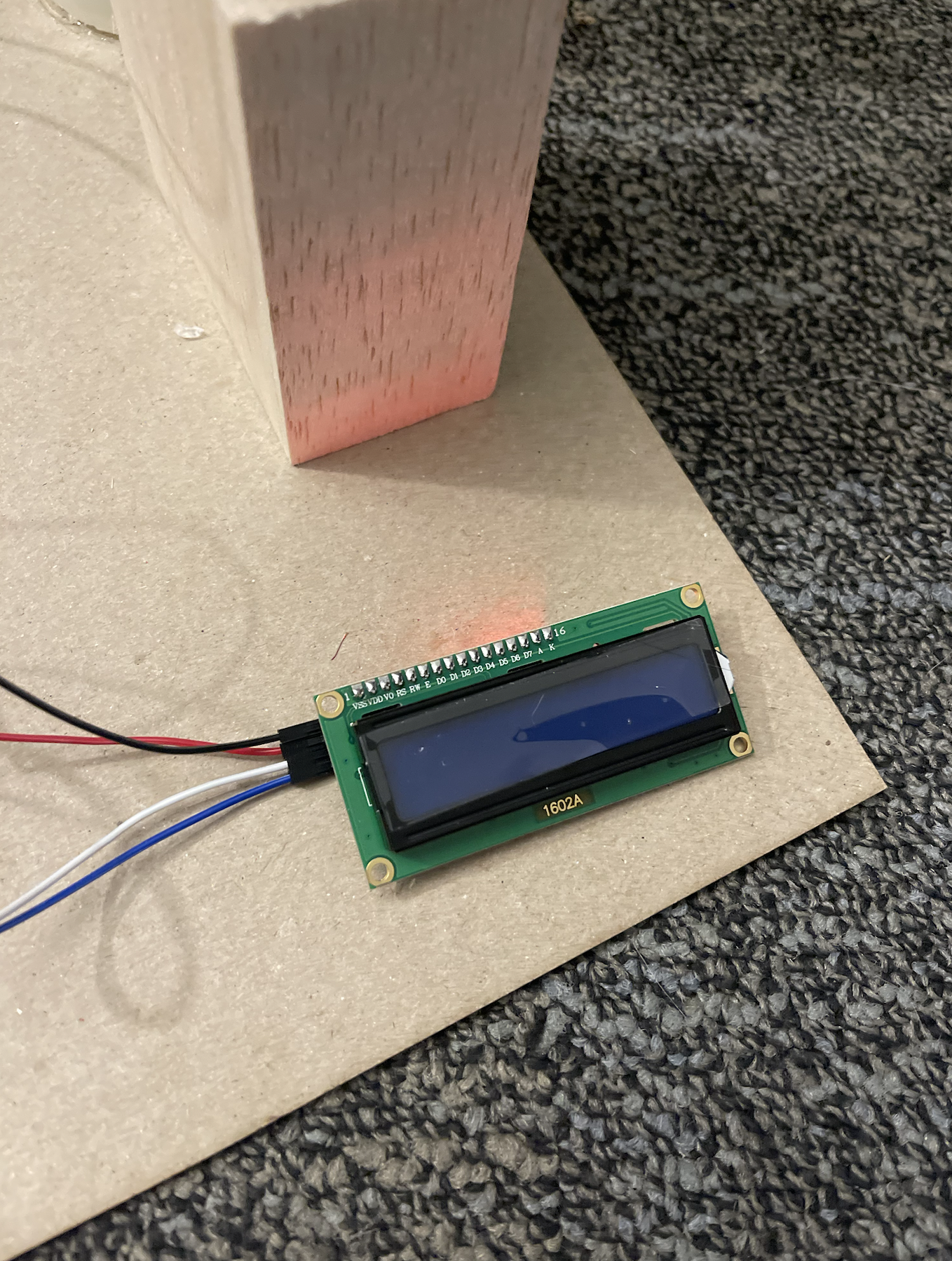
When trying to get LCD Screen to work, the code would run on the simulator, but not on the actual LCD Screen. Finally it turned out to be a material problem.
~~~
Discussion:
This project had its ups and downs. The best part was getting exposed to such a variety of devices and getting to put together a working gadget. We learned how to combine code with hardware, wire up circuits, write block diagrams and transfer said block diagrams to real circuits.
Surprisingly, the part that was the easiest was getting the rudimentary signal to flow through the gadget (input to output). The hardest part was mapping the input signal to the output signal in a continuous fashion. The physical placing of the parts on the board was also challenging, since there were many wires and moving parts (literally) that hindered the goal of making a clean, intuitive layout.
This project was also a great way to spread one’s wings creatively, since we could pick any intermediate transducer we wanted and create a narrative with our final project. Our narrative was of a sun and moon that would rise and set due to the change in water level in the graduated cylinders.
The next step will be to focus on project 2, which is a great opportunity for us to work independently. Also losing the fixed theme, our creativity becomes more important and can be better reflected. This does not only mean a bigger challenge, but also an opportunity for us to make more progress. We hope to use the experience we have gained to better our next project.
// Double Transducer: Transparency -> Rotation -> Water Level
// Contributors: Cameron, Ethan
// Date: 2/15/23
// This code facilitates the signal inputted by the photoresistor into an output signal
// to the servo motor, which triggers a signal to the potentiometer which signals the
// persitaltic pump.
//
//                   ---------------------------
//                   |   PIN        |  LABEL   |
//                   ---------------------------
//                   | PHOTORESPIN  |    A0    |
//                   | LEDPIN       |    6     |
//                   | PUMPPIN1     |    3     |
//                   | PUMPPIN2     |    4     |
//                   | SERVOPIN     |    10    |
//                   | POTENTPIN    |    A5    |
//                   ---------------------------
// LCD Code from https://courses.ideate.cmu.edu/60-223/s2023/tutorials/I2C-lcd
// by Robert Zacharias


// LCD
#include <Wire.h>
#include <LiquidCrystal_I2C.h>
LiquidCrystal_I2C screen(0x27, 16, 2);
int x = 123;

const int PHOTORESPIN = A0;
const int  PHOTOMIN = 5;
const int PHOTOMAX = 980;


const int LEDPIN = 6;
const int LEDMAX = 255;
const int LEDMIN = 0;

const int PUMPPIN1 = 3;
const int PUMPPIN2 = 4;

#include <Servo.h>
Servo motor;
const int SERVOPIN = 10;
const int  ROTMIN = 0;
const int ROTMAX = 150;

const int POTENTPIN = A5;
int POTENTMAX = 631;
int POTENTMIN = 276;

// GLOBALS
int rot = 0;
int new_rot = 0;

// MACROS
#define min(a, b) ((a) < (b) ? (a) : (b))
#define max(a, b) ((a) > (b) ? (a) : (b))


//LCD SCREEN
void lcd_loop(int photoVal, int rotVal, int potVal, int ml){
  // just count up to show x changing (the rest of the text will remain untouched)
  screen.setCursor(0, 0);
  screen.print("i:");
  screen.print(photoVal);
  screen.print("  m:");
  screen.print(rotVal);

  screen.setCursor(1, 9);
  screen.print(" ->");
  screen.print(potVal);
  screen.print(" o:");
  screen.print(ml);

  delay(1000);
}

// set ups
void potent_setup(){
  pinMode(POTENTPIN, INPUT);
}


void pump_setup(){
  pinMode(PUMPPIN1, OUTPUT);
  pinMode(PUMPPIN2, OUTPUT);
}

void photo_setup(){
  pinMode(PHOTORESPIN,INPUT);
}

void servo_setup(){
  motor.attach(SERVOPIN);
}

void led_setup(){
  pinMode(LEDPIN, OUTPUT);
}

// led loop
void led_loop(int i){
  Serial.print("LED AT LEVEL: ");
  Serial.println(i);
  analogWrite(LEDPIN, i);
}

// photo loop
int photo_loop(){
  int photoVal = analogRead(PHOTORESPIN);
  Serial.print("Photo lvl: ");
  Serial.println(photoVal);
  return photoVal;
}


// pump loop
int pump_loop(){
  Serial.println("Turning on pump");
  int diff = abs(new_rot - rot);
  // if(diff < 50){
  //   return;
  // }
  int time = map(POTENTMIN + diff, POTENTMIN, POTENTMAX, 800, 3000);
  // (we turned CW)
  if(new_rot > rot){
    Serial.print("We are pumping CW for this many ms: ");
    Serial.println(time);
    digitalWrite(PUMPPIN1, HIGH);
    delay(time);
    digitalWrite(PUMPPIN1, LOW);
  }
  // (we turned C'CW)
  if (new_rot < rot){
    Serial.print("We are pumping CCW for this many ms: ");
    Serial.println(time);
    digitalWrite(PUMPPIN2, HIGH);
    delay(time);
    digitalWrite(PUMPPIN2, LOW);
  }
  delay(time);
  return time;

}

// servo loop
int servo_loop(int photoVal){
  int rot = map(photoVal, PHOTOMIN, PHOTOMAX, ROTMIN, ROTMAX);
  Serial.print("Servo rot: ");
  Serial.println(rot);

  motor.write(rot);
  // return its rotation
  return rot;
}

// potentiometer loop
int potent_loop(){
  int potVal = analogRead(POTENTPIN);
  Serial.print("Pot val: ");
  Serial.println(potVal);

  // return its potential
  return potVal;
}


//*********

void setup() {
  Serial.begin(9600);

  // debug_setup();

  // LCD
  lcd_setup();
  // pump
  pump_setup();
  // photo
  photo_setup();
  //servo
  servo_setup();
  //led
  led_setup();
  // potent
  potent_setup();

}
int i = 0;
bool reset = 0;

void loop() {
  if(reset){
    //fill debug
    digitalWrite(PUMPPIN2, HIGH);
    delay(1000);
    digitalWrite(PUMPPIN1, LOW);
    delay(1000);
  }
  else{
    Serial.println();

    // // debug_loop();

    led_loop(255);

    // read in from photo resistor
    int pV = photo_loop();

    // trigger server
    int sV = servo_loop(pV);

    // servo physically triggers potent

    // read in potent
    new_rot = potent_loop();
    POTENTMAX = max(POTENTMAX, new_rot);
    POTENTMIN = min(POTENTMIN, new_rot);

    // trigger pump
    int ml = pump_loop();

    lcd_loop(pV, sV, new_rot, ml);

    rot = new_rot;
    delay(1000);

    i += 10;
    if(i >= LEDMAX){
      i = LEDMAX;
    }
  }


}


void lcd_setup() {
  // initialize the screen (only need to do this once)
  screen.init();

  // turn on the backlight to start
  screen.backlight();

  // set cursor to home position, i.e. the upper left corner
  screen.home();
  // print the words Hello, world! onto the screen starting at the above cursor position
  screen.print("Hello, world!");

  // move cursor to column 0, row 1
  screen.setCursor(0, 1);
  // print text starting in that position
  screen.print("2nd row text");


  screen.display();
  screen.clear();


  // you can also display a variable on the screen
  screen.home();
  screen.print("x = ");
  screen.print(x);
  delay(1000);

  screen.clear();
}


void debug_setup(){
  Wire.begin();
  Serial.begin(9600);
  Serial.println("\nI2C Scanner");
}


void debug_loop() {
  byte error, address;
  int nDevices;

  Serial.println("Scanning...");

  nDevices = 0;
  for (address = 1; address < 127; address++ )
  {
    // The i2c_scanner uses the return value of
    // the Write.endTransmisstion to see if
    // a device did acknowledge to the address.
    Wire.beginTransmission(address);
    error = Wire.endTransmission();

    if (error == 0)
    {
      Serial.print("I2C device found at address 0x");
      if (address < 16)
        Serial.print("0");
      Serial.print(address, HEX);
      Serial.println("  !");

      nDevices++;
    }
    else if (error == 4)
    {
      Serial.print("Unknown error at address 0x");
      if (address < 16)
        Serial.print("0");
      Serial.println(address, HEX);
    }
  }
  if (nDevices == 0)
    Serial.println("No I2C devices found\n");
  else
    Serial.println("done\n");

  delay(5000);           // wait 5 seconds for next scan
}