An assistive device that prevents you from going on your phone in the morning by creating a loud buzzing noise when your phone is removed from its surface in the hour after your alarm goes off.
Moving Image
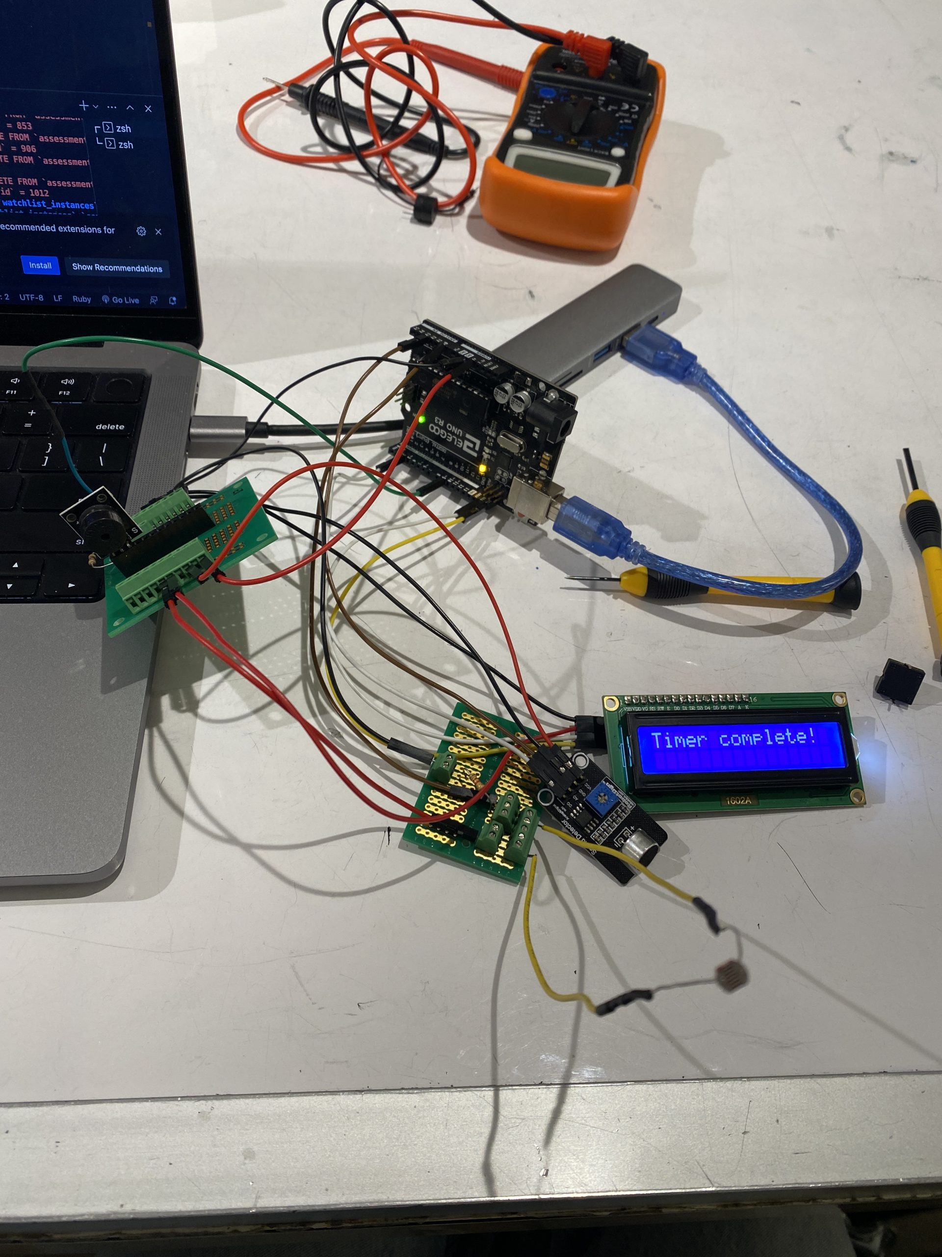
While the timer is on, removing the device will cause a buzzing noise to occur, and putting it back on makes the buzzing stop. At the end of the timer’s duration, the display shows “Timer complete!” and 3 beeps sound.
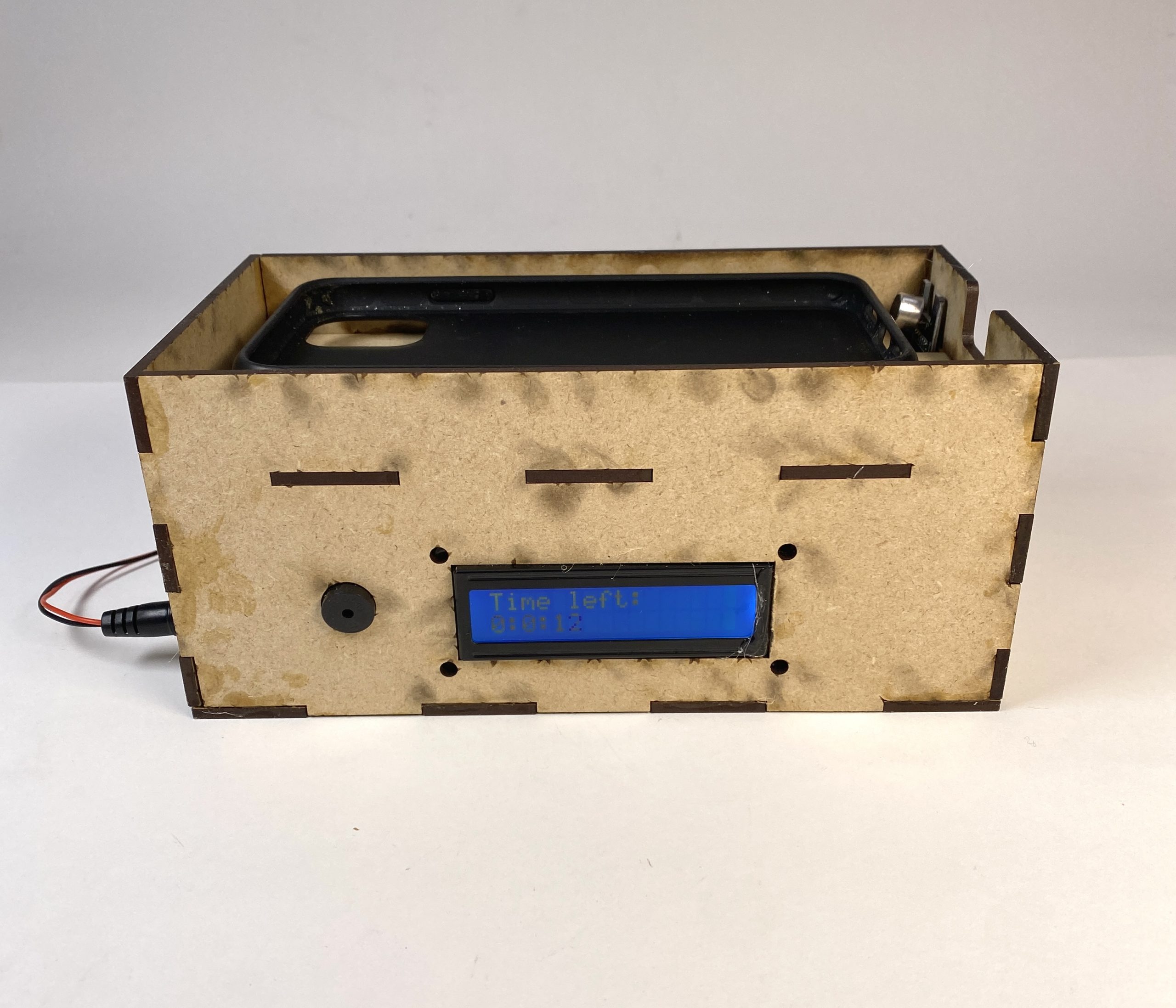
Overall Photo
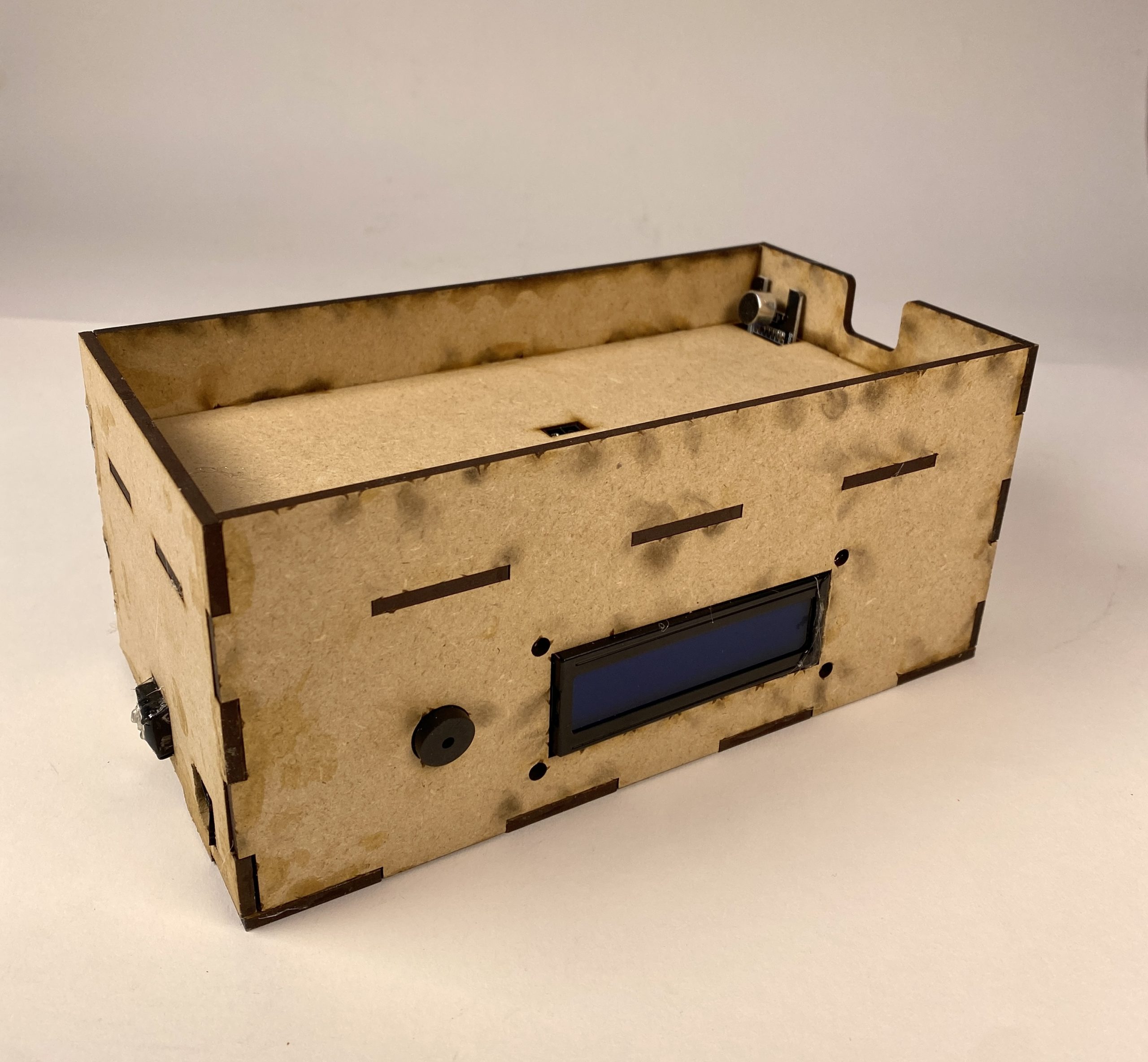
Overview of the device, with power off.
Detail Photos
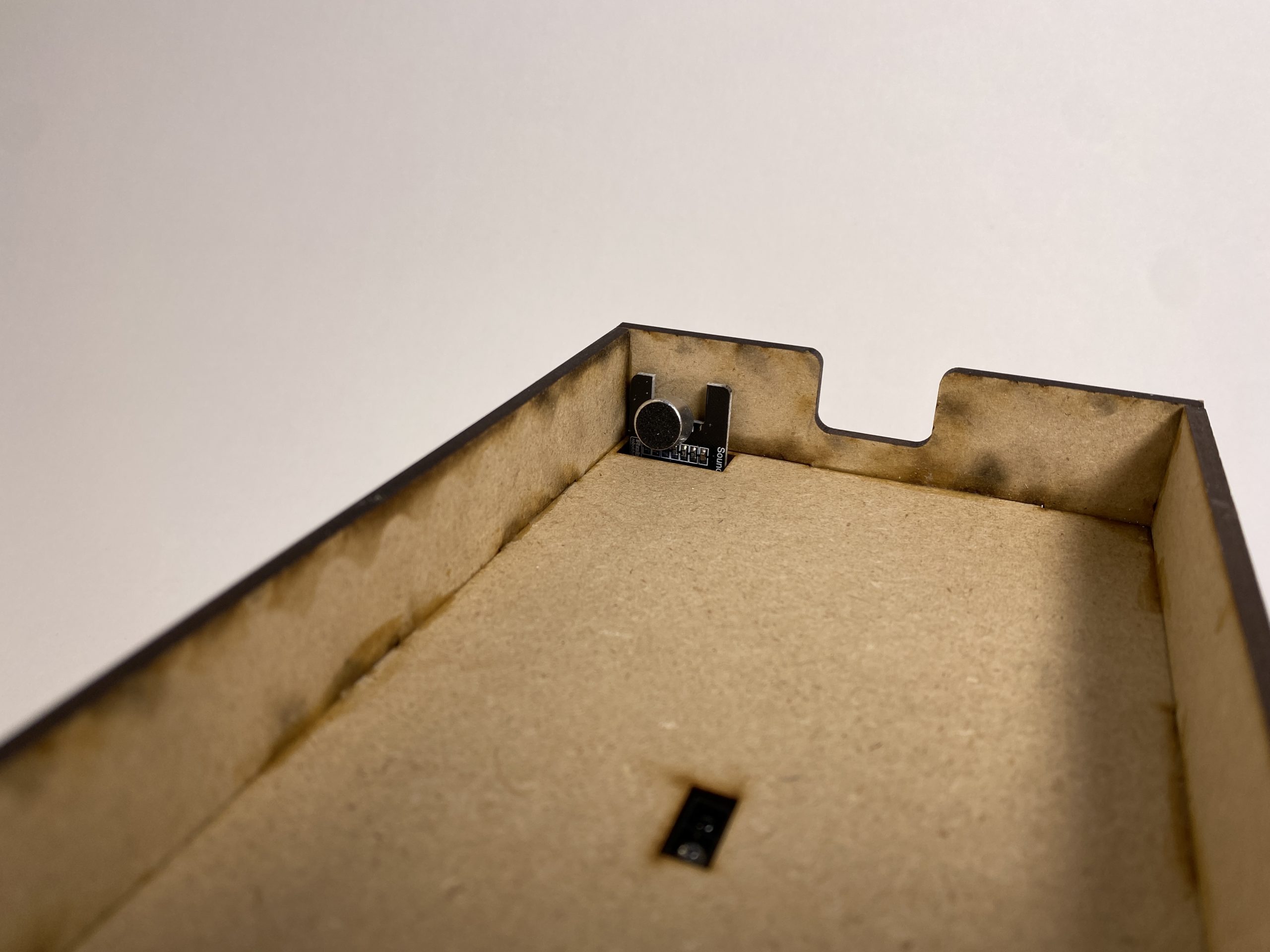
The top of my device: there’s a rectangle cutout at the top where my proximity sensor is placed. At the edge, I have another hole cut out to place the microphone directly facing the speaker of my phone, to pick up as much sound as possible. On this same side, there’s also a cutout for my charger to go into, so that I can charge my phone at night.
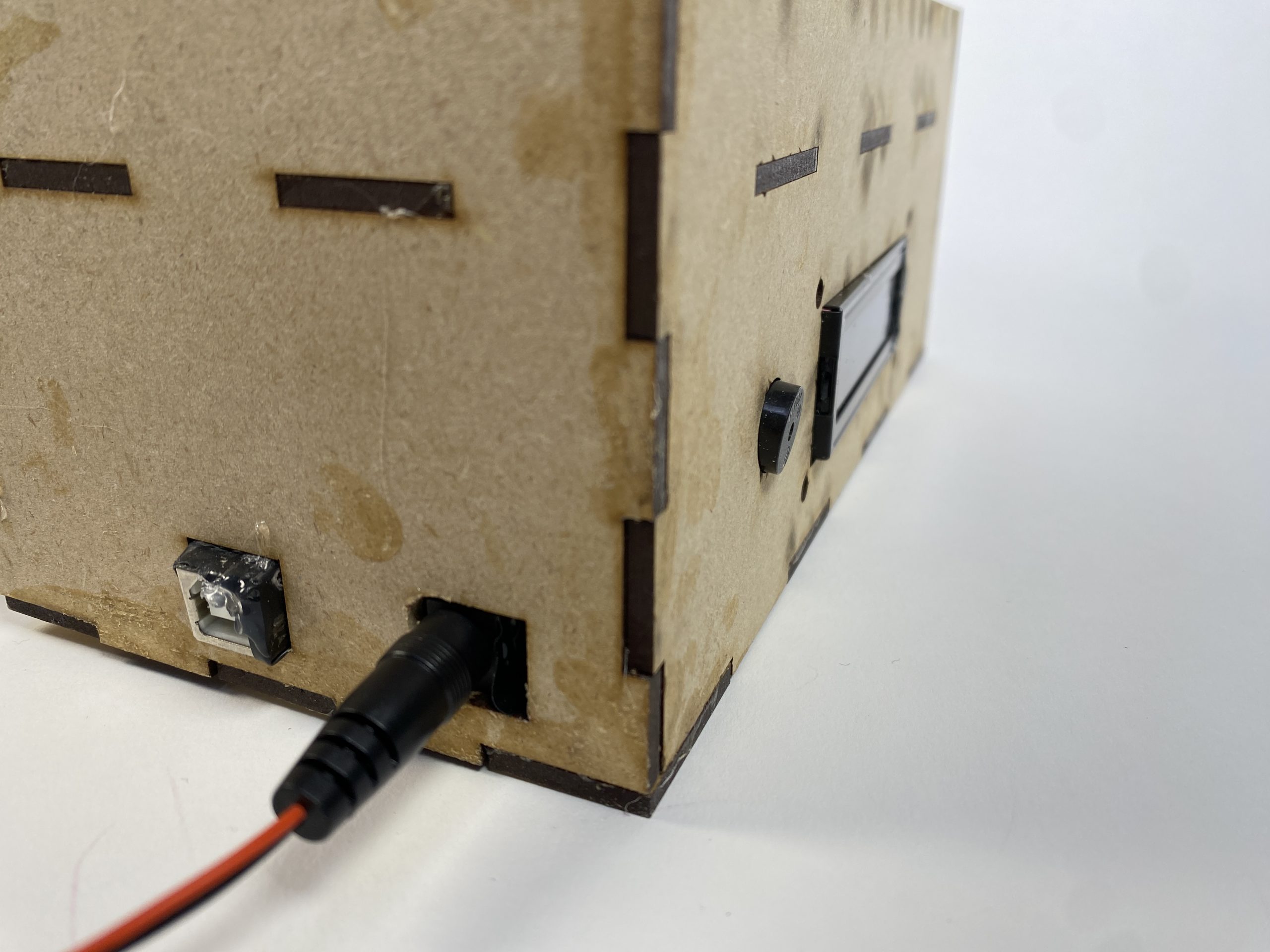
The back-view of my device, where the power source can be plugged in. There’s a hole for a port to be connected to my laptop, so that I can upload any new Arduino code to adjust some parameters, as well as a DC jack.
Using the Device
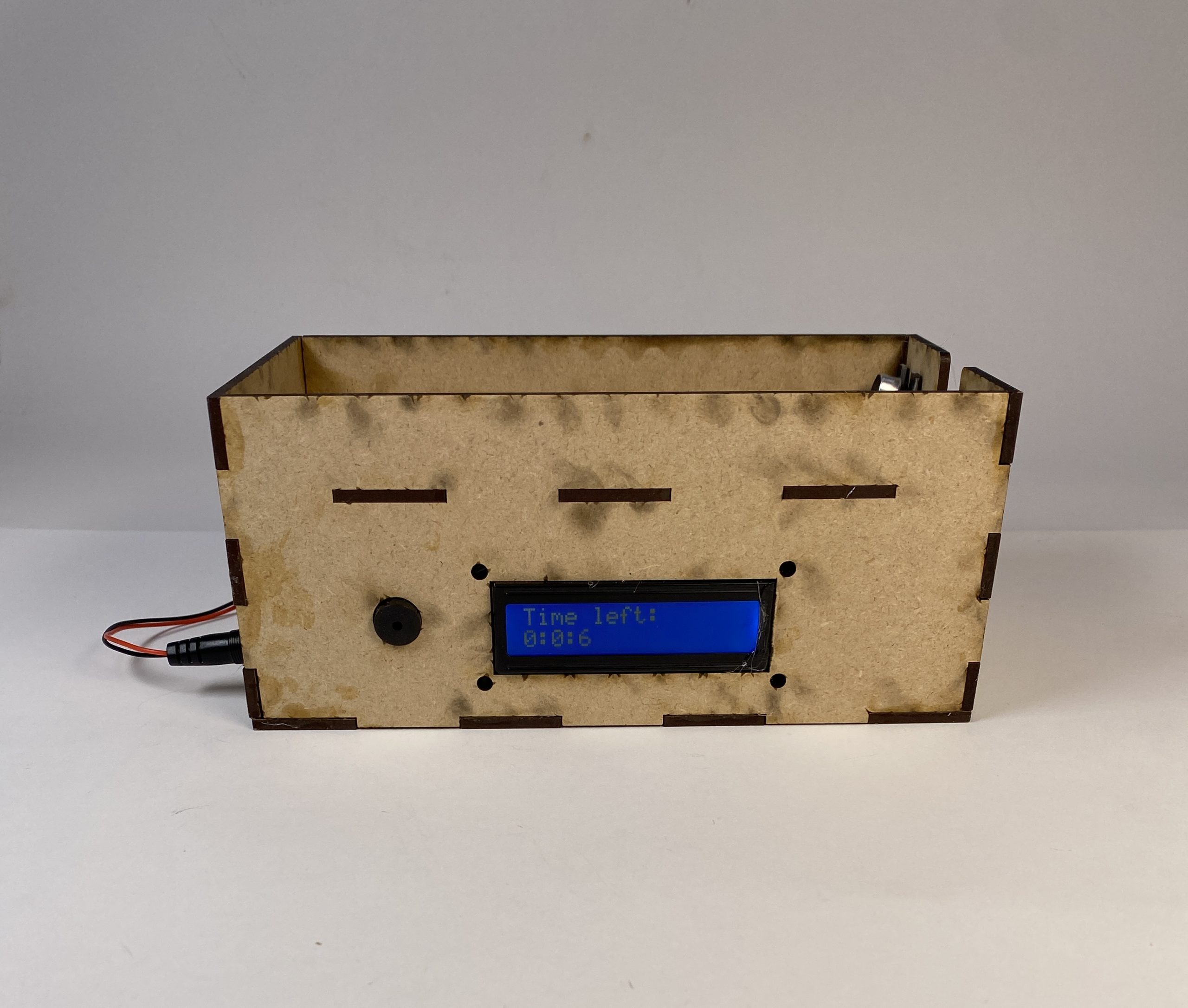
The device in use, with the timer in session and no phone.
The device in use, with the phone (phone case used as substitute for sake of taking photo) present.
Process
Throughout the design and development of my project, there were a few key design decisions that had to be made. The first was the mechanism for detecting my phone’s presence. I originally was going to use a photo-resistor to detect the presence of my phone, but during my prototype presentation, some of my classmates pointed out that the photo-resistor may get incorrectly triggered by room darkness. This was especially a concern for me because my room is often quite dark in the mornings when I wake up before sunrise. A classmate recommended I use an Optical Proximity Sensor instead, so I decided to switch to that method instead.
The first prototype of my device, with all of the wiring set up. This iteration features the photo-resistor as mechanism for detecting my phone’s presence, before switching it to an optical proximity sensor.
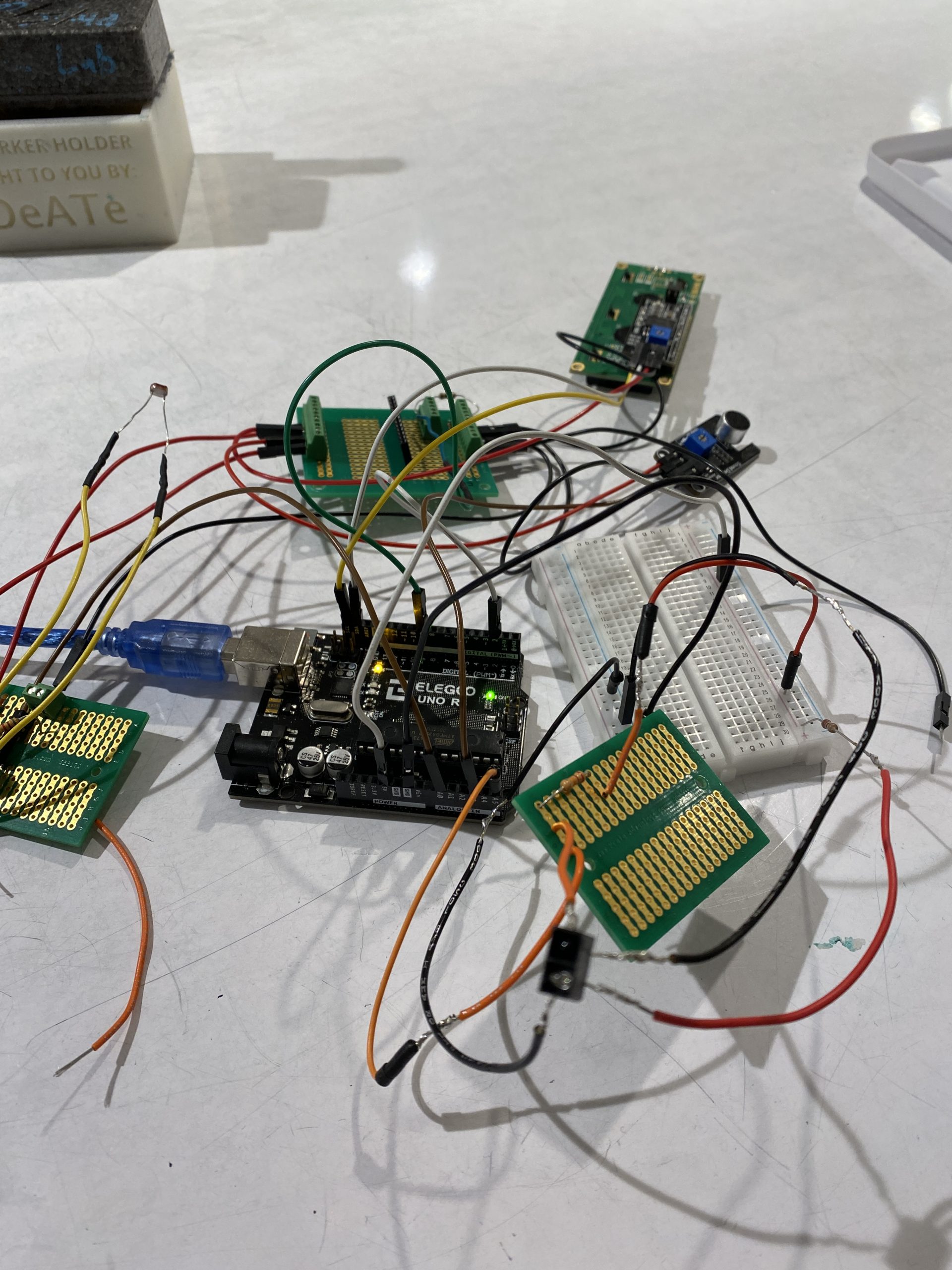
The second prototype of my device, with the photo-resistor switched out for a proximity sensor.
Another decision I made was to have the device be triggered by a microphone that can detect when my alarm goes off, rather than having an RPC module and setting a time for when the phone detection activates every morning. This made sense for my daily habits, as integrating it with when my alarm goes off most accurately ties in with my wake-up schedule, and also goes along with my regular routine of setting my alarm on my phone. If I wanted to set the timer on the device directly, I would probably have had to implement a full alarm system to make sure that the lock activates when I wake up. This would have been a lot of additional work for not much additional value, as it would’ve been more inconvenient to set the alarm on a separate device anyways. I also was unsure if any of the output devices on-hand could generate a sound as loud as my phone.
Process Images
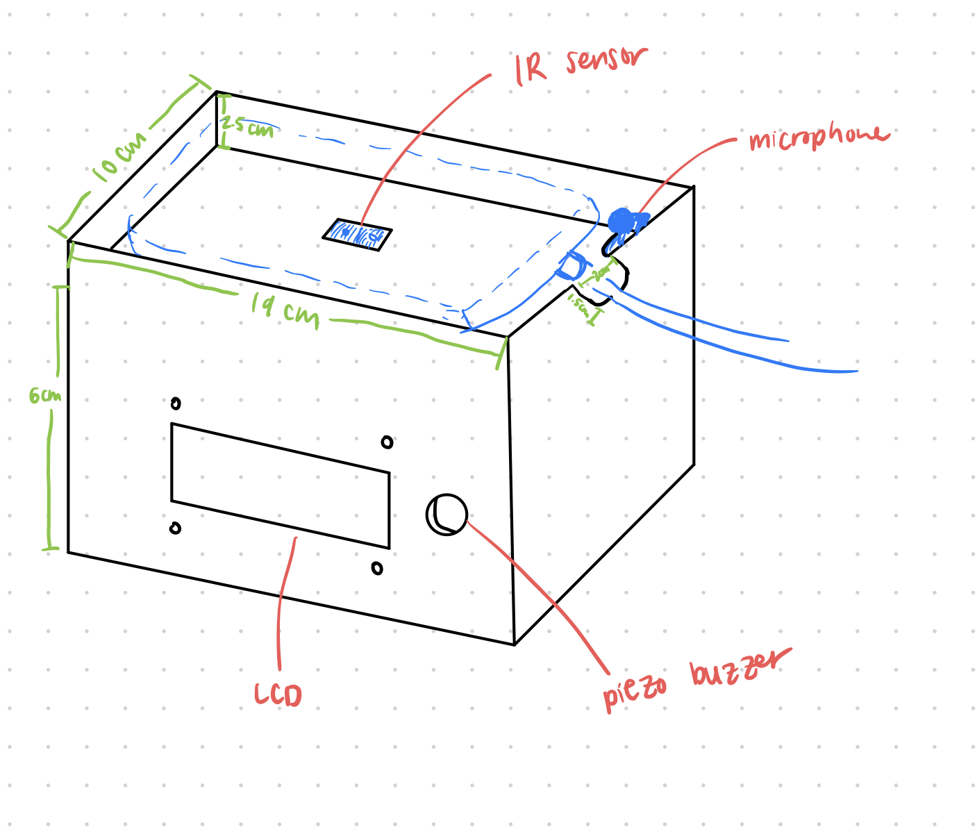
Initial sketch of my device before modeling it on Autodesk Fusion, during the ideation process.
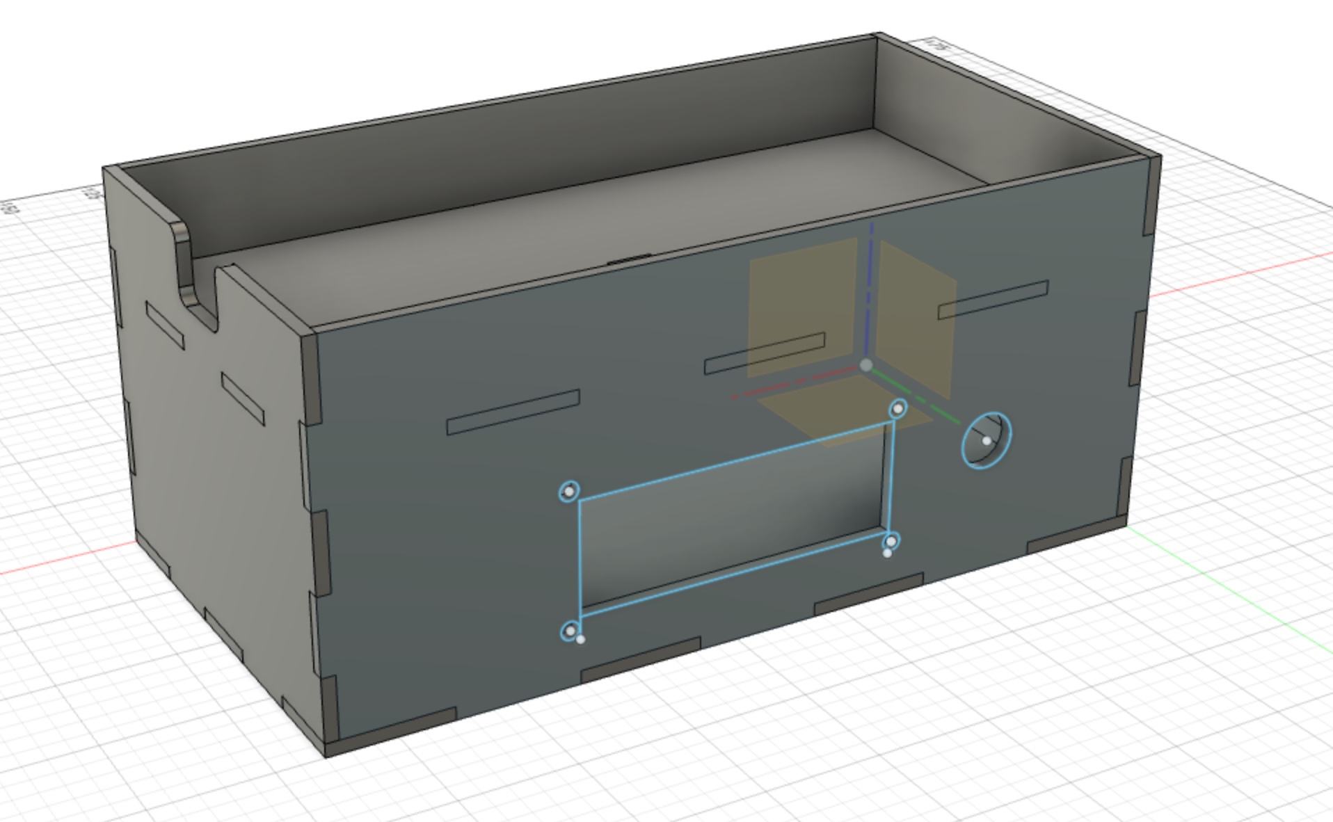
Autodesk fusion model of the box to be laser-cut. This was my first time ever doing any modeling or using Autodesk Fusion, so it was quite a challenge to design everything and model it. In the end, I was really happy with how it came out!
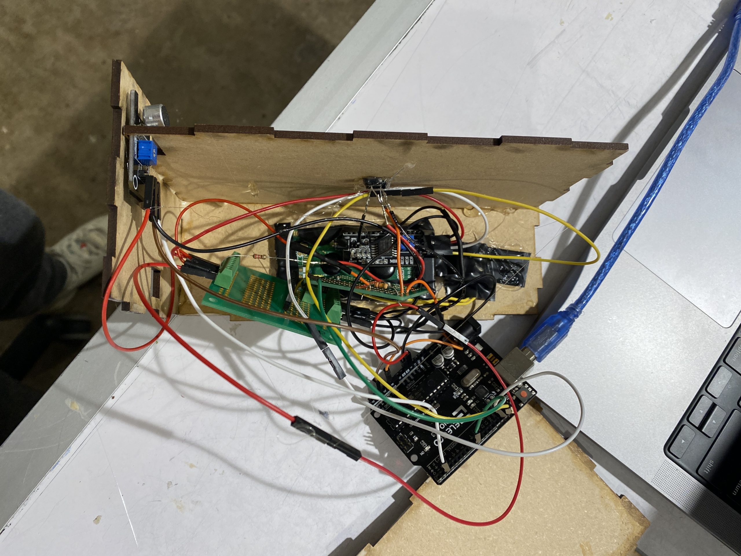
Beginning to put the electronics components in the 3D printed box. This was a lot trickier than expected, because I had to do a lot of rearranging to account for where each component should poke out from in the box.
Discussion
Overall the process of creating this project was super fun, but challenging! It was really cool to think about the ergonomic aspect of this project and to create a device I may actually use, especially coming from Project 1, which was mostly focused on the electronics aspect. I am super happy with the results, although there are a few things I would change, some of which were also pointed out during critique.
“You could potentially try to make it sensitive to the phone so that the object is not tricked by anything else”
This is definitely the biggest thing I would change if I were to create another iteration of my project. Currently, a big limitation in my device is that it’s very easy to “trick” it into thinking my phone is there, by placing any arbitrary object on the device. Since the IR sensor only detects some sort of presence, I could easily pick up my phone and block the sensor with something else. In a future iteration, I would either supplement this method of detection with another one, or to replace the IR sensor entirely. One possible method is to lay out a few IR sensors in the shape of the perimeter of my phone, such that they are placed right under where the edges of my phone would be, as well as a few on the outside of the perimeter. Then, the device would only recognize my phone there if the sensors on the perimeter detect a presence, and the ones outside of the perimeter don’t. This would ensure that the object placed has to be exactly the shape of my phone for it to stop the buzzing. One limitation of this idea is that I could still dupe the phone by cutting an object to be the same shape, or strategically placing things on top of the inside perimeter sensors. However, this would be a lot more work to “trick” than placing any arbitrary object on top, which would probably be enough to prevent me from wanting to override it. Another method would be to switch out the proximity sensor for a pressure sensor, but again, I could also dupe this if I found a similarly weighted object to my phone. Plus, if I really wanted to stop the device I could just unplug it anyways.
“Potentially have a potentiometer or some other method to adjust the waiting period”
This was definitely something I thought of doing during ideation, but I ultimately decided to hard-code the timer, as I didn’t want to give myself an easy way to lessen the waiting period and instead force myself to go the full 60 minutes. In retrospect, though, I definitely agree that this might be helpful and could still keep me accountable if I set, say, 45 or 60 minutes as a “lower limit” to the timer, and only allowed myself to adjust the timer up. This is definitely something I would consider doing in a future iteration.
Besides the changes described above, something else I would want to do is to refine the form of my device. Right now, it’s a bit clunky, and the bottom portion is a bit large since I wasn’t very space-efficient in my wire management. Since it was my first time fabricating, the appearance was also a bit clunky, with some accidental cutouts I didn’t mean to include, as well as lots of glue everywhere. I also would want to add an “emergency override” button. One idea that I had been thinking about in my ideation to avoid making this “emergency override” make me less accountable was to add time, say 5 minutes, to the timer for the next lock session every time I pressed it. I also would want to refine the microphone threshold a bit more, as it was still slightly too sensitive, and would get triggered if there was a super loud noise that wasn’t my phone.
Overall, though, I’m super happy with how my project came out! My main goal of this project was to build a useful device for myself and to fabricate something I could be proud of, which I think I definitely satisfied. While there were a few things I would like to refine, especially regarding the form, I am still pretty happy with it, especially given that it was my first time using a laser-cutter or doing any sort of modeling or physical prototyping. In general, I learned a lot about both the technical side of fabrication (i.e. using the software), as well as the design-thinking it takes to plan out the form factor and ergonomics of a physical device. I also definitely learned that fabrication can take multiple iterations to get right, and to not underestimate how long this might take in the future. Next time, I would also plan out the electronics part more in tandem with the physical form. This time, I did all of the wiring first without thinking much into how I would put everything together into the final physical device at the end, and then did all the modeling and laser-cutting after this. This caused me to have to spend a lot of time reconfiguring my wiring to fit into the device and trying to cram it in, which could’ve been avoided if I had thought about the physical form more and knew things like approximately how long to make the wires, which parts should be wired closer together, etc.
Technical Information
Block Diagram

Schematic

Code
/*
* Good Morning Phone Jail
* Michelle Liu
*
* An assistive device that prevents you from going on your phone in the morning by
* creating a loud buzzing noise when your phone is removed from its surface in the
* hour after your alarm goes off.
*
* Pin Map:
  variable name | mode | pin | description
  -----------------------------------------------
  SOUND_GATE_PIN | input | 2 | detect sound from mic
  SOUND_ENVELOPE_PIN | input | A3 | read sound from mic
  PHOTO_PIN | input | A0 | reads IR sensor data
  BUZZER_PIN | output | 9 | makes buzzing noise
*
* Credits:
*
* LCD display code referenced from the course website:
* https://courses.ideate.cmu.edu/60-223/s2023/tutorials/I2C-lcd
*
* Piezo buzzer code:
* https://www.instructables.com/How-to-use-a-Buzzer-Arduino-Tutorial/
*/


#include <Wire.h>
#include <LiquidCrystal_I2C.h>

LiquidCrystal_I2C screen(0x27, 16, 2);

const int SOUND_GATE_PIN = 2;
const int SOUND_ENVELOPE_PIN = A3;
const int PHOTO_PIN = A0;
const int BUZZER_PIN = 9;

const int SOUND_THRESHOLD = 300;
const int LIGHT_THRESHOLD = 320;

// actual mode (60 min)
const unsigned long WAIT = 60 * 60 * 1000;

// demo mode (30 sec)
//const unsigned long WAIT = 30000;

boolean timerActive = false;
unsigned long timer = 0;
int dispDelay = 0;

void setup() {
  Serial.begin(9600);
  pinMode(SOUND_GATE_PIN, INPUT);
  pinMode(PHOTO_PIN, INPUT);
  pinMode(BUZZER_PIN, OUTPUT);

  screen.init();

  // set cursor to home position, i.e. the upper left corner
  screen.home();

  timerActive = false;
}

// convert milliseconds to a string for display on the LCD
String millisToString(unsigned long currentMillis) {
  unsigned long seconds = currentMillis / 1000;
  unsigned long minutes = seconds / 60;
  unsigned long hours = minutes / 60;
  unsigned long days = hours / 24;
  currentMillis %= 1000;
  seconds %= 60;
  minutes %= 60;
  hours %= 24;
  return (String(hours) + ":" + String(minutes) + ":" + String(seconds));
}

// print the current amount of time left on the timer
void printTime() {
  screen.clear();
  screen.setCursor(0, 0);
  if (!timerActive) {
    screen.noDisplay();
    screen.noBacklight();
  } else {
    screen.backlight();
    screen.display();
    screen.print("Time left: ");
    screen.setCursor(0, 1);
    unsigned long timeLeft = WAIT - (millis() - timer);
    screen.print(millisToString(timeLeft));
  }
}


void loop() {
  int sound = analogRead(SOUND_ENVELOPE_PIN);

  printTime();

  // case 1: timer is currently active
  if (timerActive && millis() - timer < WAIT) {
    int photo = analogRead(PHOTO_PIN);

    // play a sound if no device is detected
    if (photo >= LIGHT_THRESHOLD) {
      tone(BUZZER_PIN, 500);
    } else {
      noTone(BUZZER_PIN);
    }
  } else if (!timerActive && sound >= SOUND_THRESHOLD) {
    // case 2: alarm detected -> activate the timer

    // start timer
    timerActive = true;
    timer = millis();
    Serial.print("Timer activated: ");
    Serial.println(sound);
    noTone(BUZZER_PIN);
  } else if (timerActive && millis() - timer >= WAIT) {
    // case 3: time is up -> deactivate timer & turn off buzzer
    timerActive = false;
    timer = millis();

    noTone(BUZZER_PIN);
    screen.clear();
    screen.setCursor(0, 0);
    screen.print("Timer complete!");

    // beeping sound to indicate timer is complete
    for (int i = 0; i < 5; i++) {
      tone(BUZZER_PIN, 1000);
      delay(200);        // on for 1 sec
      noTone(BUZZER_PIN);     // Stop sound
      delay(200);
    }
    delay(3000);
  } else {
    timer = millis();
    noTone(BUZZER_PIN);
  }
  delay(300);
}