0. Project Introduction
We are Team Guava, and our client is Shaude.
Over the weeks, we talked to and interacted with Shaude to get to know her better and to understand what she does. From those conversations, we were able to find and target aspects of her life that we could help to improve, such as picking fallen things up, helping her paint, and assisting her in communicating, especially in the morning.
Link to previous post: https://courses.ideate.cmu.edu/60-223/s2023/work/interview-with-shaude-team-guava/
1. What We Built
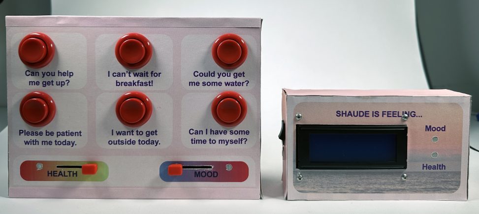
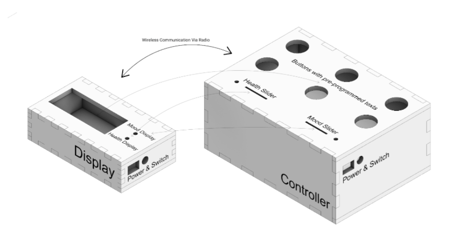
By having two boxes that can communicate with each other at a distance, we can give our client, Shaude, the ability to communicate with someone in her home much easier than a smartphone. In particular, we had one device for the client’s bedside that could send up to six predetermined messages for specific needs and two adjustable gradient indicators for both general mood and health to another device that could be placed anywhere in the home for the ease of the caretaker. We also made it so both devices run based on a wall outlet, removing the need to change batteries in the product.

Controller (left) and Display (Right)
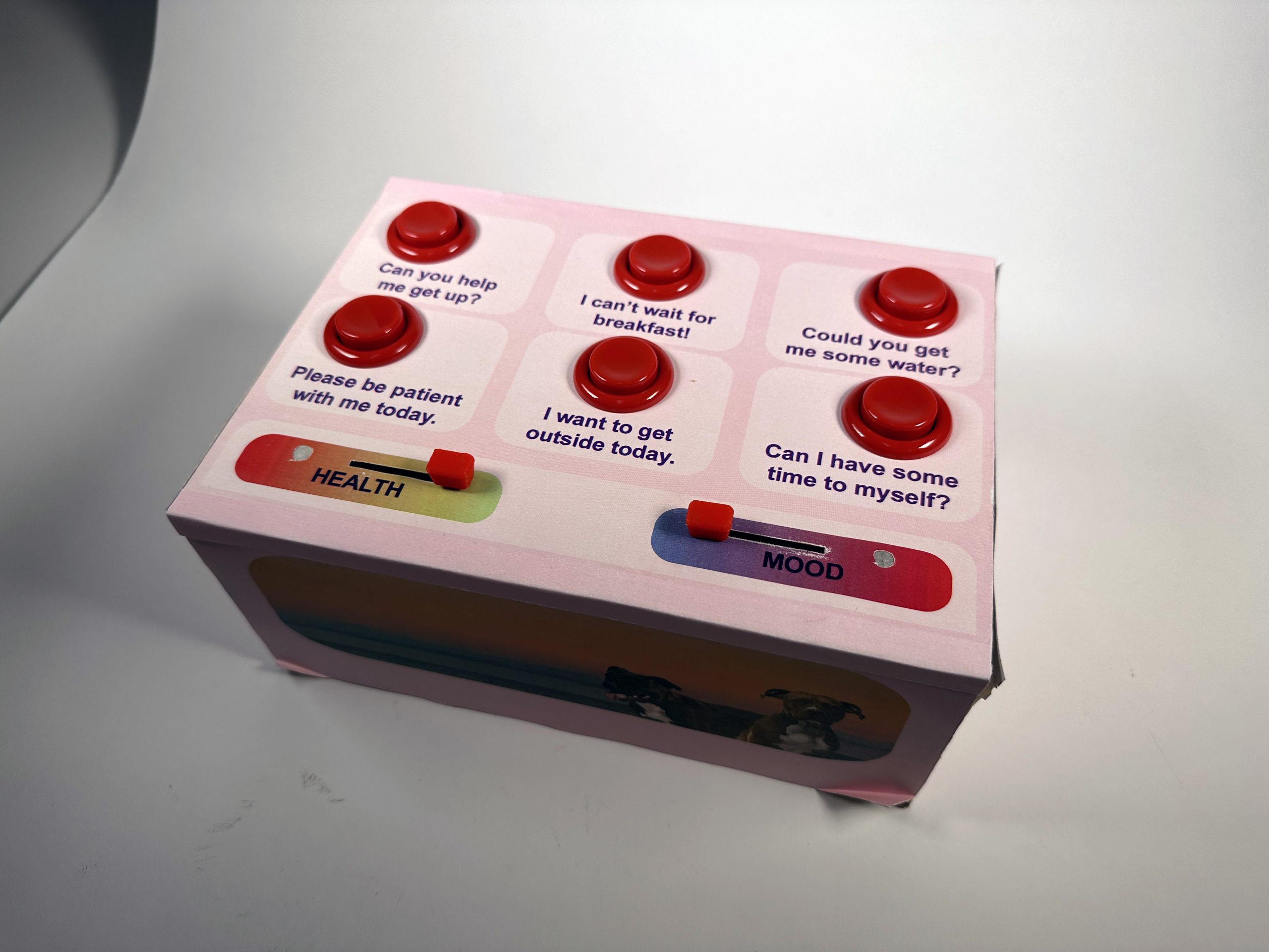
Controller – Custom Slider Cap, Arcade Buttons, Sticker Papers
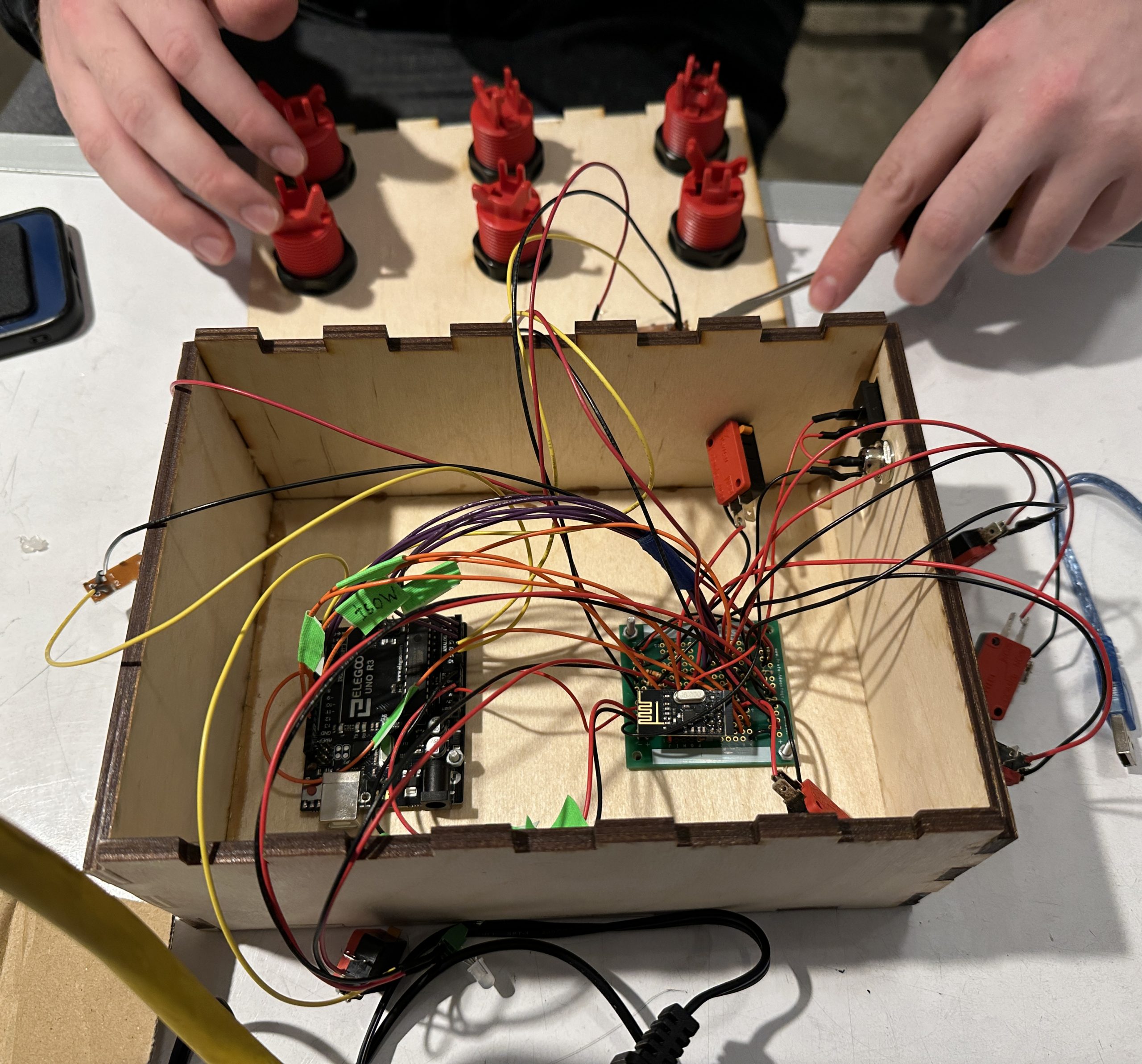
Controller – Internal Wiring
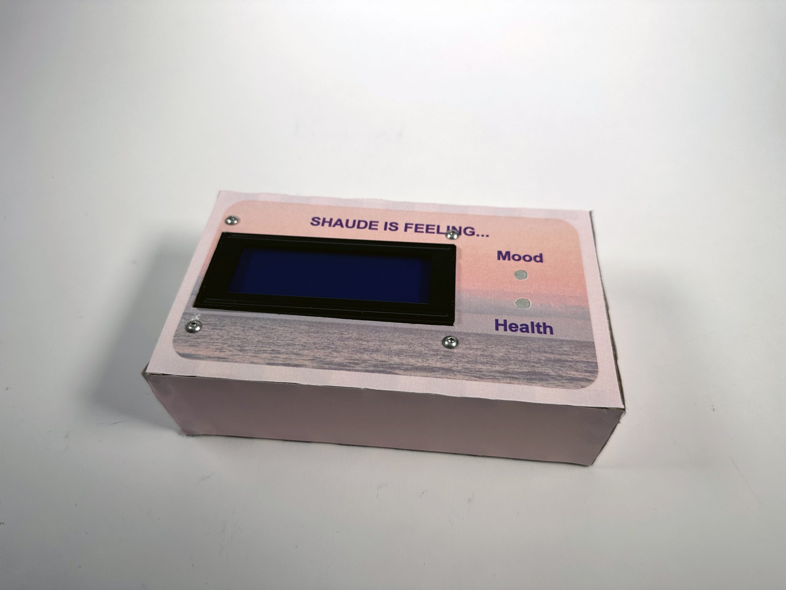
Display – LCD
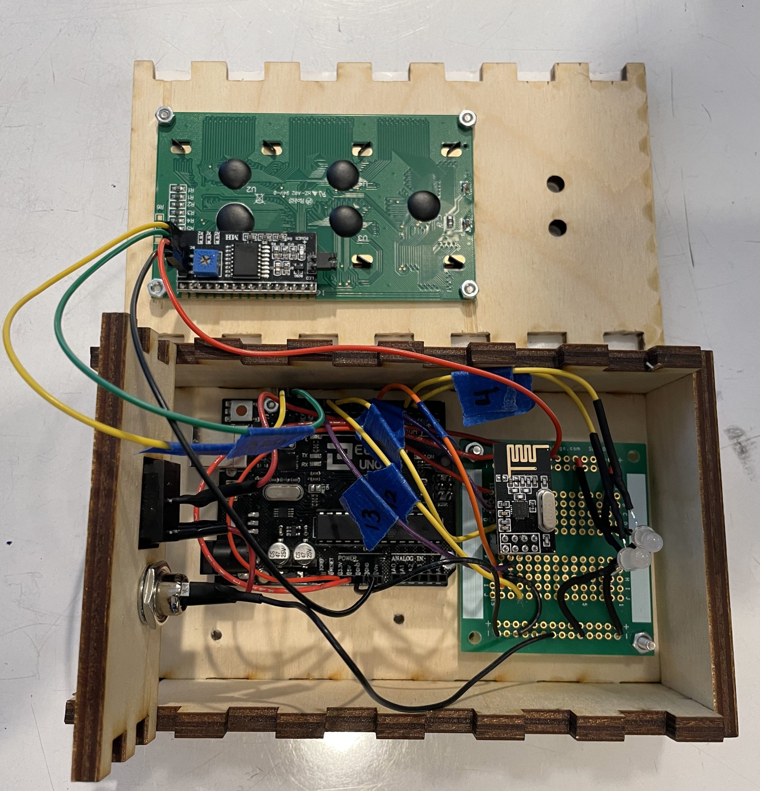
Display – Internal Wiring
By having two boxes that can communicate with each other at a distance, we can give our client, Shaude, the ability to communicate with someone in her home much easier than a smartphone. In particular, we had one device for the client’s bedside that could send up to six predetermined messages for specific needs and two adjustable gradient indicators for both general mood and health to another device that could be placed anywhere in the home for the ease of the caretaker. We also made it so both devices run based on a wall outlet, removing the need to change batteries in the product.
Video of Our Devices Working as Intended.
Narrative sketch of how our product works
2. Prototypes and Processes
Our first prototypes were built in order to answer the following questions:
- What inputs and outputs we wanted to use?
- Such as how should Shaude enter her emotions and how should they be shown
- What colors and gradients made the most sense for out purpose
- Should we use light color or brightness?
- What scale should the device be at
- What should be the layout of the device
We made a lot of prototypes testing the hardware that we would be using, such as the radio, the potentiometers and the Neo pixel bulbs. These were practical prototypes to see how the coding and functionality would look like. We also printed prototypes of the housing so we would be able to better address scale. Some prototypes were simple drawings exploring how different aspects of the outputs might be, such as drawing of different light gradients or LED configurations.
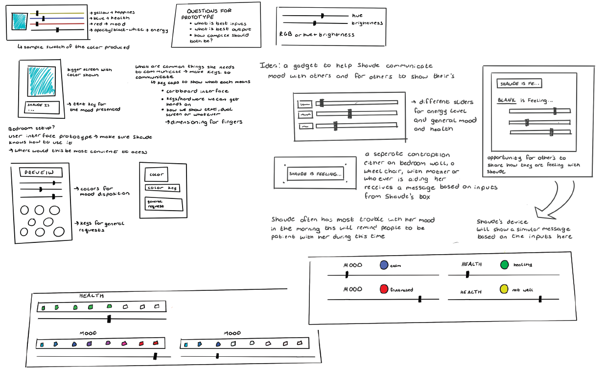
These sketches show our thought process behind our questions, and some things we wanted to explore in our prototyping.
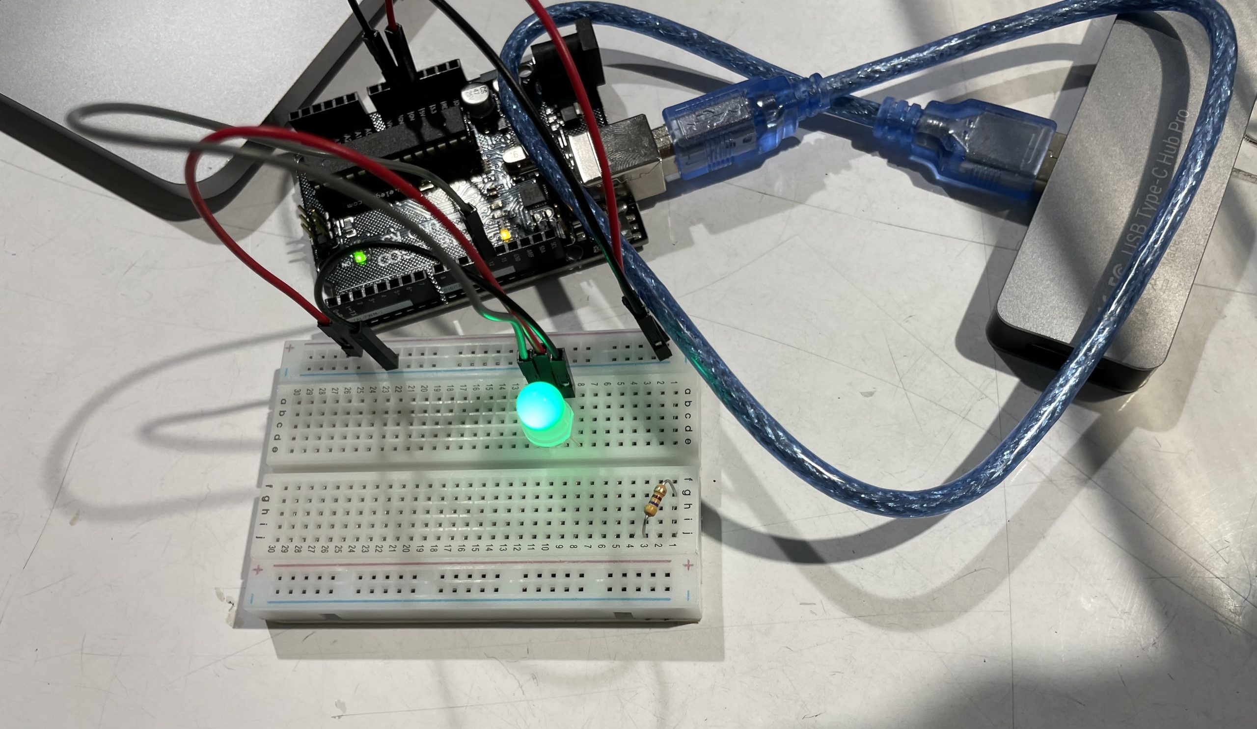
Neopixel bulb light up for the first time (emotional)
This was our first version of slider to lights. This simple setup controlled the red blue and green value on the Neopixel. You can see that they all run to the same bulb and effect each other. The position on the slider effects the brightness of each color in the bulb. We were happy with this experiment because it was much like mixing paint, but with light, and it was fun to play with.
Above is second iteration of the potentiometer to lights. We tested mapping specific gradients to the lights. Here you can green to red as well as red to blue. You may notice the weird jump from blue to red in the lights. This was a coding issue we needed to battle and happens because the red value is much stronger than the blue.
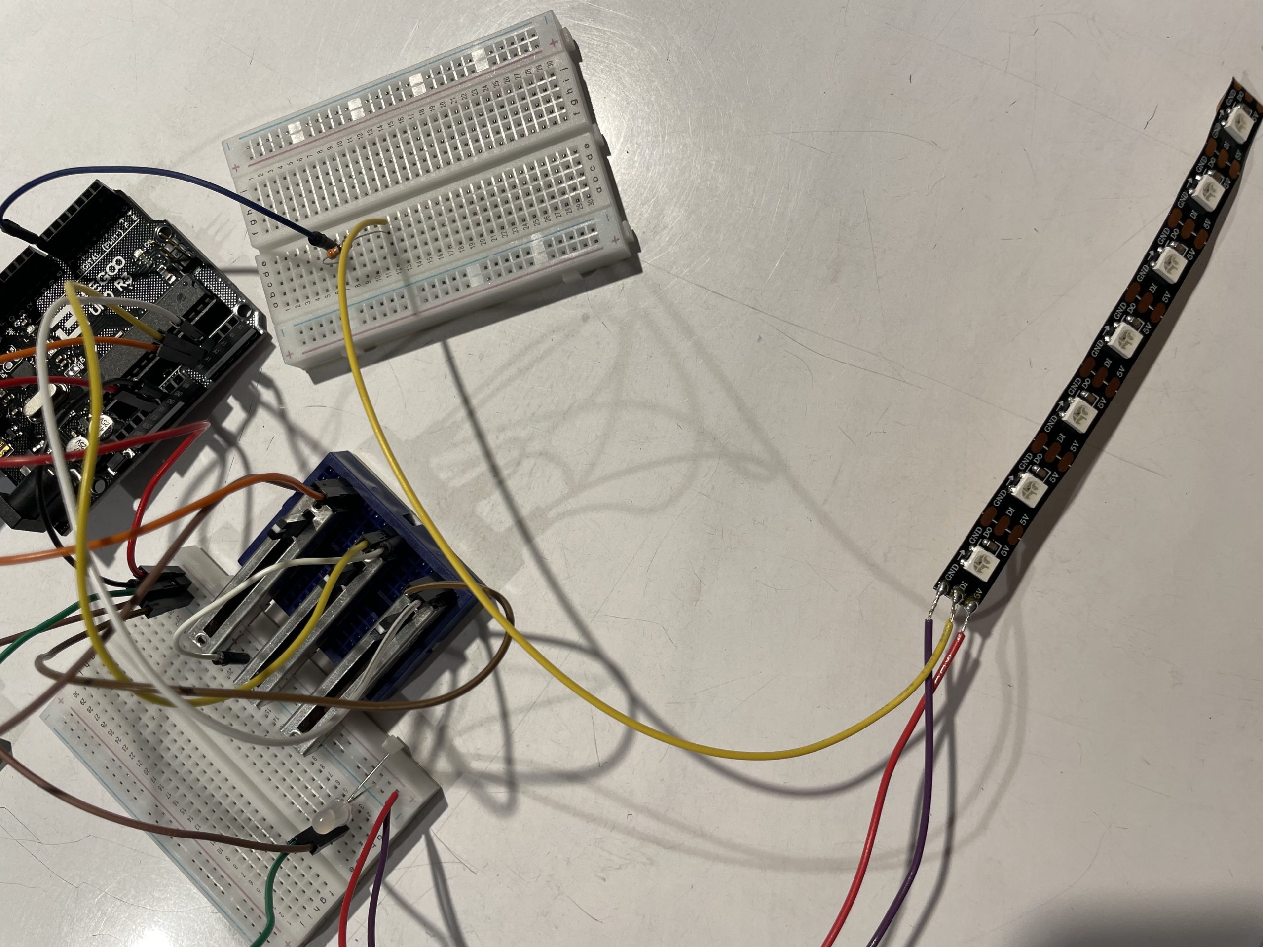
LED strip alternative to neopixel attempt
This idea correlated to a sketch seen above, where the amount of mood or health corelates to a number of bulbs illuminated on the LED strip. This idea was scraped because it seemed a little confusing and added a layer of complexity that was unnecessary. This porotype was never brought to a fully functional level.
Above you can see a video of us testing the connection between two Arduinos using Arduino. The input is the press of a button and the output is a message displaying on an LCD screen.
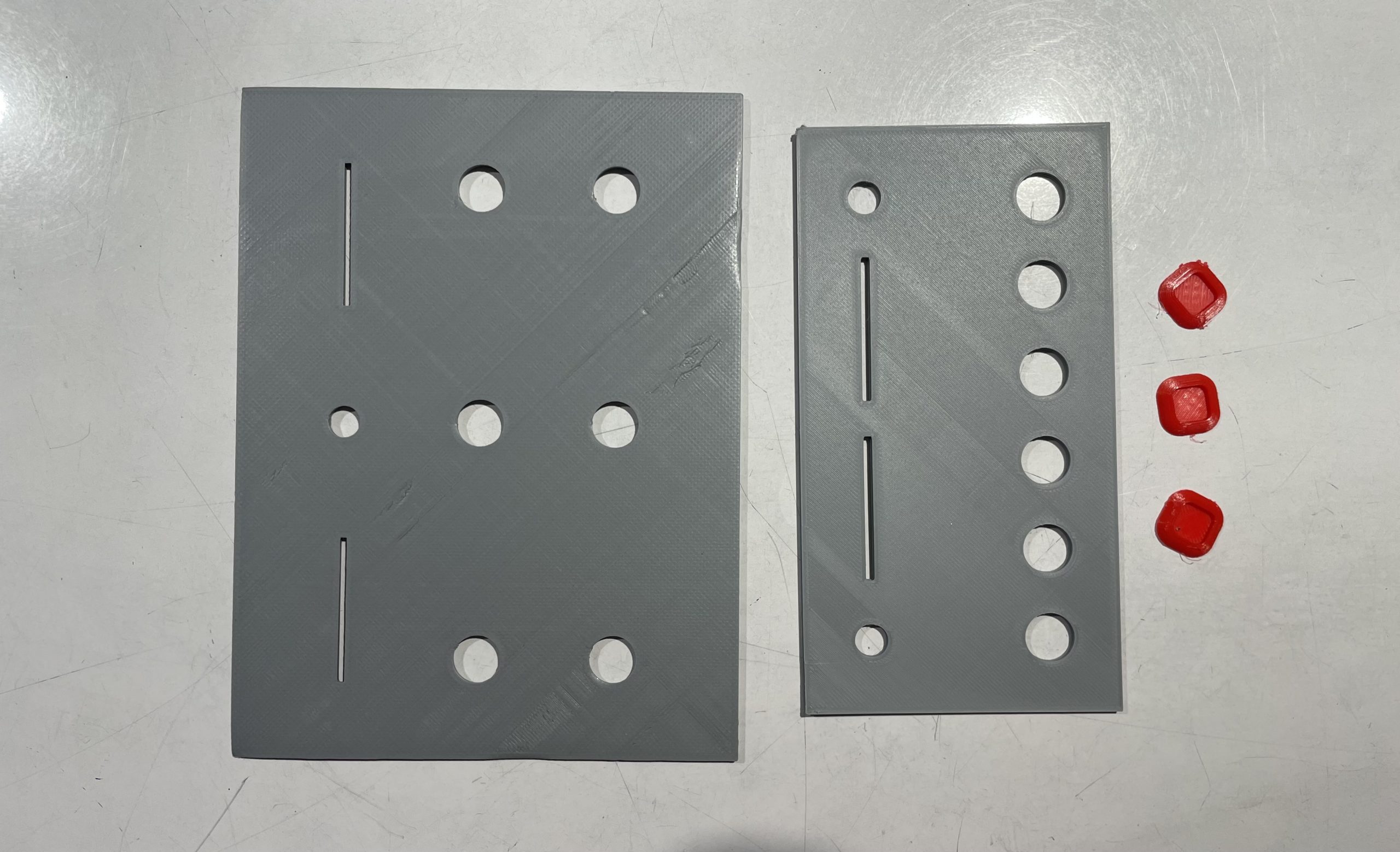
physical prototypes
To test how big we wanted to control panel to be we printed a few panel to show to Shaude for layout and scale. We also wanted to test using button caps to make the buttons differentiated and easier to press. These caps did not end up working because they attached onto the tops of the buttons and were not deep enough to create a snug fit.
We learned the most from our prototypes after discussing the outcomes with Shaude. After showing her the scale of the models we learned that she needed much bigger buttons, and a big display box for her to see what the options on the box were. She also noted that she preferred a flat down view of the box rather than a slanted one. She enjoyed the potentiometers and the feedback of the lights. We talked to her about what colors she connected with different expressions and moods. We were then able to use this information to decide on our final color gradients that would be most descriptive and helpful to her. The range of these colors were red to blue for agitated to calm and green to red for health to ill. We also discussed her favorite colors and such so we could design the box to be most pleasing to her later on. Her favorite colors by the way are purple and pink, and she really likes dogs.
During our prototyping process we were surprised by how the neopixel colors values are not all equal. The power and brightness of the red really overpowered the blue and we had difficulty mapping the values to get a noticeable gradient from blue to red. If we had more time to prototype we would have liked to explore other visual methods and hardware for showing the gradients and values of colors. We had one drawn idea of utilizing strip LEDs to use both color and value to show mood and health (see above), but it seemed to add a layer of confusion, especially with calm and agitation. We chose to continue with the Neopixel bulbs because they were simple to read and true to our original intent. Overall going further with our design we took the work from our prototypes and simply made them better suited for Shaude.
3. Conclusions and Reflections
Overall, our group thought that our product successfully fulfilled our client’s identified needs. Through interview and iteration, we were able to come up with a device that allowed the communication of both specific desires and more general moods in a concise and effective way. However, the process did involve challenges, not the least of which was working with our client. Working in an environment like CMU, we are often surrounded by people of similar dispositions who know what we can accomplish. This project allowed us to work with someone with a disability who had none of these attributes. In particular, we often found it hard when speaking or working with Shaude to get actionable feedback or find specific problems that were within our skills to address. This unexpected difficulty forced us to change how we interacted with Shaude in our second interview. Instead of open-ended questions where we expected her to give us actionable answers, we provided her with a list of possible options or user interfaces. This narrowed the scope of choices and discussion, allowing her to point out any general issues in all the possibilities. For instance, when we were giving her options on how the buttons were laid out, she expressed that even the most prominent option we had was too small. This informed us of a significant issue we must be aware of. Next time, I would like to schedule periodic meetings with Shaude at the beginning of the project to increase her involvement in our process and interview her caretaker to get a feel for their opinion on the output device.
The final crit was an informative and valuable process. Our team felt that those present gave good feedback on what we did well and what we could have done better as a final project. In particular, the one we felt was most true was regarding the layout of the mood and health potentiometers, “The ‘mood’ light felt backward, and the red/blue color scheme was hard to decipher any middle ground.” This was a comment that a couple of people gave us because the mood and health sliders went opposite directions to increase/decrease, which needed to be clarified, and the spectrum for the mood light (red to blue) was hard to see any interim values. With more time, we would fix this by flipping one of the potentiometers so that both are the same and choosing better colors to the spectrum between. Another comment we got was to improve the “Robustness of the device. Add texture or images to buttons, which is something we would want to do. We were considering making our buttons at one time, which could have allowed us to do this. Making it even easier by allowing buttons to be differentiated by feel or image instead of just clarifying what each does by text. Another useful feedback was about having a message on the receiving device for too long. This could be addressed by “adding some kind of ‘acknowledge’ button to the remote receiver, which would then silence the message and blank out the screen.” This is something that we should have considered and is a problem. Because it teaches the recipient that messages are not current, decreasing the device’s effectiveness. We did have difficulties with the radio, and getting two-way communication instead of one-way would be a challenge that we felt would have taken more time than we had. Finally, someone commented, “Bedside table space can be limited, so a slightly smaller bedside device” would be better. We agree and think that its height might also become an issue. If we could do it again, the solution would be to cut the arcade buttons in half, which would have worked because the buttons’ electrical and physical components could be separated. The buttons took up the majority of the space inside the input box.
To sum up, this device solves a real problem in Shaude’s life. Hopefully, it gets used, and no issues pop up over long periods of use, but we don’t think they will. It was an exciting experience that Team Guava was happy to be a part of.
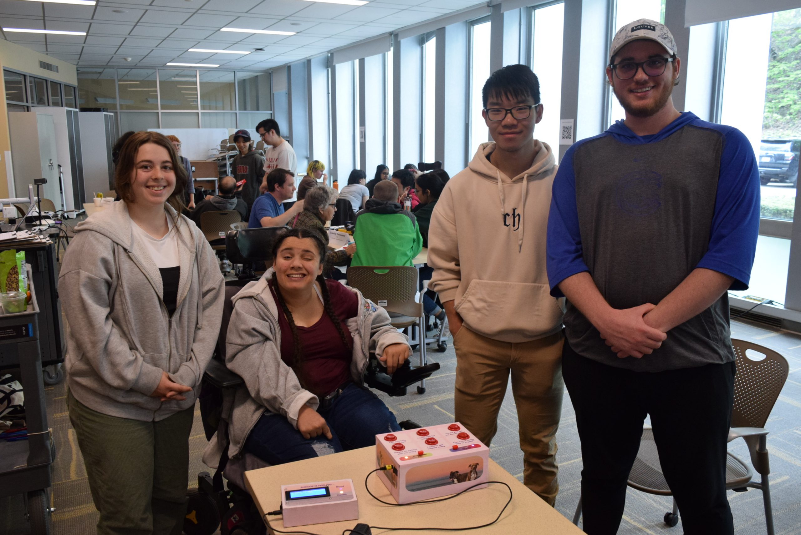
Final project, Shaude, and Team Guava at final Critique
4. Technical Details
Block Diagrams:

Block diagram showing input and output flow for Shaude’s portion of communicator
Output Device Block Diagram

Receiver block diagram
Electrical Schematics:

Electrical Schematic of Input device for Mood communicator

Receiver Wiring diagram
Code:
/*
 * Mood Communicator, input code, final project
 * By: Andres Montemayor, Evette Lacomb, Dunn Zhang

 Description: The code below takes in inputs from buttons, and sliding potentiometers
 then, displays a gradient from red to blue and red to green based on the pot values
 it also transmits those values over a NRF24L01 radio to another arduino

 Pin Map:
  POTPIN1     | input    | potentiometer: sets mood gradient
  POTPIN2     | input    | potentiometer: sets health gradient
  BUTTON1     | input    | reads when message 1 button pressed, sets integer for radio to send
  BUTTON2    | input        | reads when message 2 button pressed, sets integer for radio to send
  BUTTON3    | input        | reads when message 3 button pressed, sets integer for radio to send
  BUTTON4    | input        | reads when message 4 button pressed, sets integer for radio to send
  BUTTON5    | input        | reads when message 5 button pressed, sets integer for radio to send
  BUTTON6    | input        | reads when message 6 button pressed, sets integer for radio to send
  moodLed   | output        | outputs rgb value to neopixel to show potentiometer value on spectrum(red->blue)
  healthLed | output       | outputs rgb value to neopixel to show potentiometer value on spectrum(red->green)

NRF24L01 pin map can be seen below
 *
 * radio pin    Arduino Uno/Nano pin    Arduino Micro pin
 * VCC          3.3V                    3.3V
 * GND          GND                     GND
 * CE           7                       7
 * CSN          8                       8
 * MOSI         11                      MO
 * MISO         12                      MI
 * SCK          13                      SCK

 * modified from code by: Alton Olson, Vicky Zhou, Seema Kamath, Robert Zacharias, Andres Montemayor, Evette Lacomb
 Credit:
 Used example libraries from relevant libraries for relevant sections
 for radio code, it was provided by Robert Zacharias and then later adjusted by team to better fulfill project
 parameters.
 *
 */

//Libraries in use in this code
#include <SPI.h>
#include <nRF24L01.h>
#include <RF24.h>
#include <Wire.h>
#include <PololuLedStrip.h>
// numbers in <> are pin numbers for the leds to display mood and health, reference for what is transmitted
PololuLedStrip<2> moodLed;
PololuLedStrip<4> healthLed;

//LED initialize count. We use a single neopixel so only one, if use a strip would be more
#define LED_COUNT 1
rgb_color moodcolors[1];
rgb_color healthcolors[1];

//define integers for colors map from sliding potentiometer
int red;
int red2;
int blue;
int green;

// Initialize the pins for the buttons, potentiometer, radio, single
const int BUTTON1 = 3;
const int BUTTON2 = 5;
const int BUTTON3 = 6;
const int BUTTON4 = A2;
const int BUTTON5 = A3;
const int BUTTON6 = A4;

const int POTPIN1 = A0;
const int POTPIN2 = A1;

const int RADIO_CE = 7;
const int RADIO_CSN = 8;

int button = 0;
int POT1 = -1;
int POT2 = -1;
int send[] = {0,0,0};

//initiallize and name radio, address needs to be 6 digit and same on recieve and transmit
RF24 radio(RADIO_CE, RADIO_CSN);
const byte address[6] = "00001";

void setup() {
  // radio startup
  radio.begin();
  radio.openWritingPipe(address);
  radio.setPALevel(RF24_PA_HIGH);
  radio.stopListening();
  Wire.begin();
  // Set the pins for the potentiometers & buttons
  pinMode(BUTTON1, INPUT);
  pinMode(BUTTON2, INPUT);
  pinMode(BUTTON3, INPUT);
  pinMode(BUTTON4, INPUT);
  pinMode(BUTTON5, INPUT);
  pinMode(BUTTON6, INPUT);

  pinMode(POTPIN1, INPUT);
  pinMode(POTPIN2,INPUT);
}

void loop() {
  // read analog values from sliding pots
  POT1 = map(analogRead(POTPIN1),0,1023,0,255);
  POT2 = map(analogRead(POTPIN2),0,1023,0,255);

  //map sliding pots to colors for leds
  red = map(POT1, 0, 255, 7, 255);
  blue = map(POT1, 0, 255, 10, 0);

  red2 = map(POT2, 0, 255, 0, 255);
  green = map(POT2, 0, 255, 255, 0);

  //display color
  moodcolors[0] = rgb_color(0, red, blue);
  healthcolors[0] = rgb_color(green, red2, 0);

  moodLed.write(moodcolors, 1);
  healthLed.write(healthcolors, 1);
  // check which button is pressed to see what integer should be transmitted over radio
  if (digitalRead(BUTTON1) == LOW) {
    button = 1;
  }
  if (digitalRead(BUTTON2) == LOW) {
    button = 2;
  }
  if (digitalRead(BUTTON3) == LOW) {
    button = 3;
  }
  if (digitalRead(BUTTON4) == LOW) {
    button = 4;
  }
  if (digitalRead(BUTTON5) == LOW) {
    button = 5;
  }
  if (digitalRead(BUTTON6) == LOW) {
    button = 6;
  }
  //redefine arrey before sending based on inputs
  send[0]=POT1;
  send[1]=POT2;
  send[2]=button;

  // transmit values
  radio.write(send, sizeof(send));
  //delay so time to update led correctly
  delay(50);
}
//PROJECT 3 GUAVAS: OUTPUT CODE
//Dunn Zhang, Andres Montemayor, Evette LaComb
//SHAUDE's mood box RECEIVE code - takes the radio signal from another box and displays the inputs through screen and lights


//Pinmap:
/*  pin       mode         description
    4         output       mood Led
    3         output       health Led
    SDA       output       LCD screen
    SCL       output       LCD screen
    7         CE           radio
    8         CSN          radio
    11        MOSI         radio
    12        MISO         radio
    13        SCK          radio

NRF24L01 pinmap can be seen below
  radio pin    Arduino Uno/Nano pin    Arduino Micro pin
  VCC          3.3V                    3.3V
  GND          GND                     GND
  CE           7                       7
  CSN          8                       8
  MOSI         11                      MO
  MISO         12                      MI
  SCK          13                      SCK

 * modified from code by: Alton Olson, Vicky Zhou, Seema Kamath
 * Robert Zacharias 5-23

*/

//USE THIS CODE FOR RECIEVE
#include <SPI.h>
#include <nRF24L01.h>
#include <RF24.h>
#include <Wire.h>
#include <LiquidCrystal_I2C.h>
/// lights vvv

#include <PololuLedStrip.h>
PololuLedStrip<4> moodLed;
PololuLedStrip<3> healthLed;

#define LED_COUNT 1
rgb_color moodcolors[1];
rgb_color healthcolors[1];

int red;
int red2;
int blue;
int green;
//lights ^^^

//Initialize the LCD library with the I2C address, number of columns and rows. call it lcd
LiquidCrystal_I2C lcd(0x27, 20, 4);

const int RADIO_CE_PIN = 7;
const int RADIO_CSN_PIN = 8;

int POT1;
int POT2;
int button;
int message = -1;

RF24 radio(RADIO_CE_PIN, RADIO_CSN_PIN);
const byte address[6] = "00001";

void setup() {
  Serial.begin(9600);

  radio.begin();
  radio.openReadingPipe(0, address);
  radio.setPALevel(RF24_PA_HIGH);
  radio.startListening();
  lcd.init();
  lcd.backlight();
}

void loop() {
  // get radio input from transmitter
  if (radio.available()) {
    int readVal[3];
    radio.read(&readVal, sizeof(readVal));

    POT1 = readVal[0];
    POT2 = readVal[1];
    button = readVal[2];
    Serial.println(POT1);

    //depending on the button signal show message
    if (readVal[2] == 5 && message != 5) {
      message = 5;
      lcd.clear();
      lcd.setCursor(0, 0);
      lcd.print("Can you help me");
      lcd.setCursor(0, 1);
      lcd.print("get up?");
    }
    if (readVal[2] == 2 && message != 2) {
      message = 2;
      lcd.clear();
      lcd.setCursor(0, 0);
      lcd.print("Can I have some");
      lcd.setCursor(0, 1);
      lcd.print("time to myself?");
    }
    if (readVal[2] == 3 && message != 3) {
      message = 3;
      lcd.clear();
      lcd.setCursor(0, 0);
      lcd.print("I want to get");
      lcd.setCursor(0, 1);
      lcd.print("outside today.");
    }
    if (readVal[2] == 6 && message != 6) {
      message = 6;
      lcd.clear();
      lcd.setCursor(0, 0);
      lcd.print("Could you get");
      lcd.setCursor(0, 1);
      lcd.print("me some water?");
    }
    if (readVal[2] == 4 && message != 4) {
      message = 4;
      lcd.clear();
      lcd.setCursor(0, 0);
      lcd.print("I can't wait");
      lcd.setCursor(0, 1);
      lcd.print("for breakfast!");
    }
    if (readVal[2] == 1 && message != 1) {
      message = 1;
      lcd.clear();
      lcd.setCursor(0, 0);
      lcd.print("Please be patient");
      lcd.setCursor(0, 1);
      lcd.print("with me today.");
    }
    //colored LEDs:
    int red = map(POT1, 0, 255, 7, 255);
    int blue = map(POT1, 0, 255, 10, 0);

    int red2 = map(POT2, 0, 255, 0, 255);
    int green = map(POT2, 0, 255, 255, 0);

    moodcolors[0] = rgb_color(0, red, blue);
    healthcolors[0] = rgb_color(green, red2, 0);

    moodLed.write(moodcolors, 1);
    healthLed.write(healthcolors, 1);

    delay(150);

  }
}