
Physical Wake-up Service:
A very effective alarm clock that gives you an wake-up experience you’ve never had before.
Images:
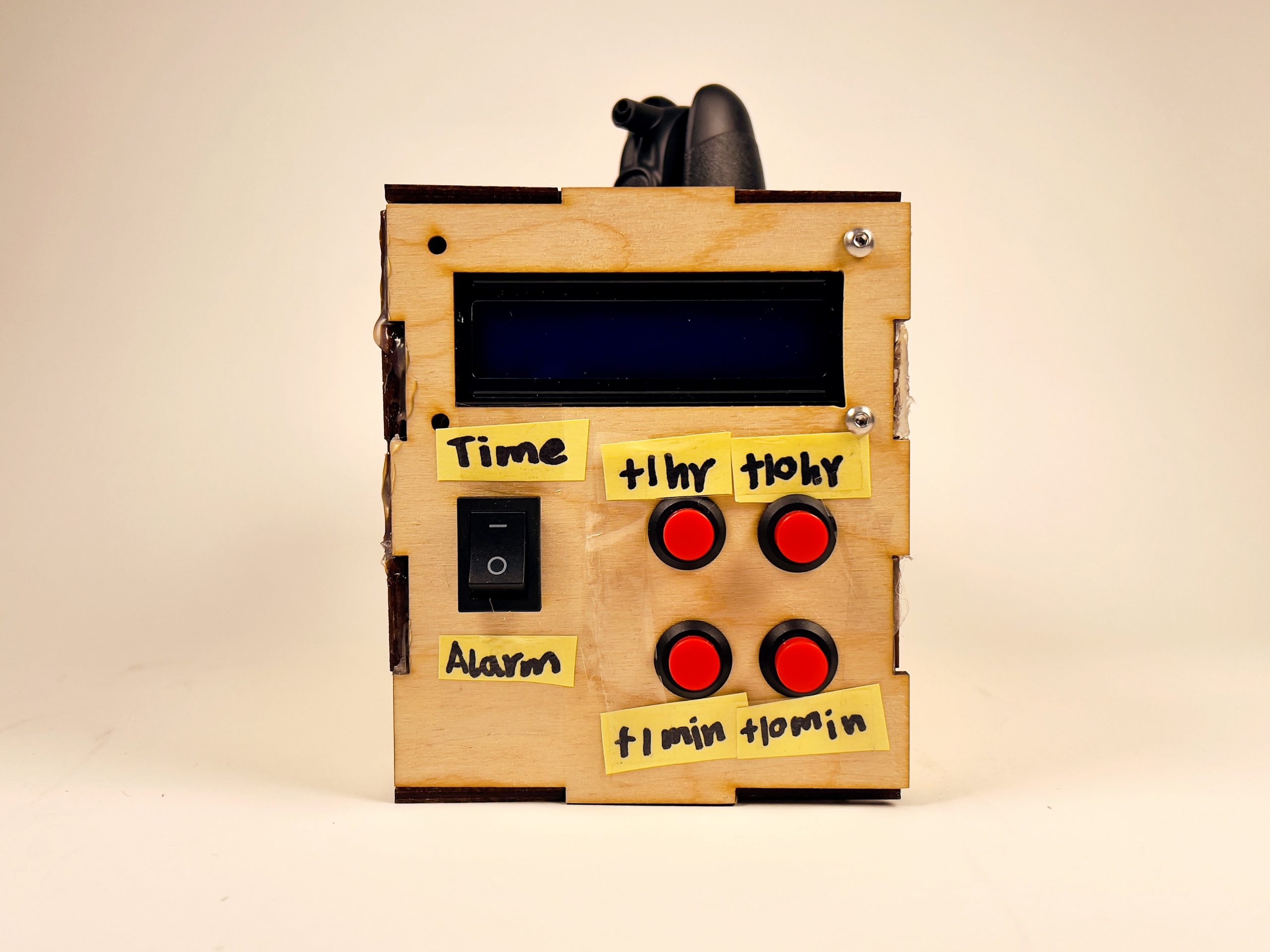
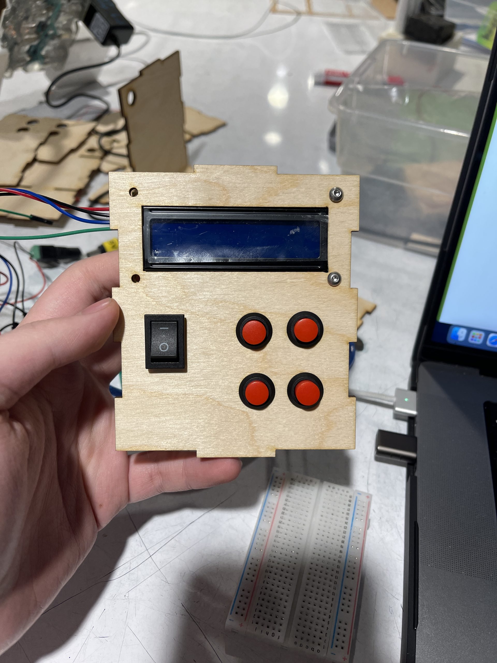
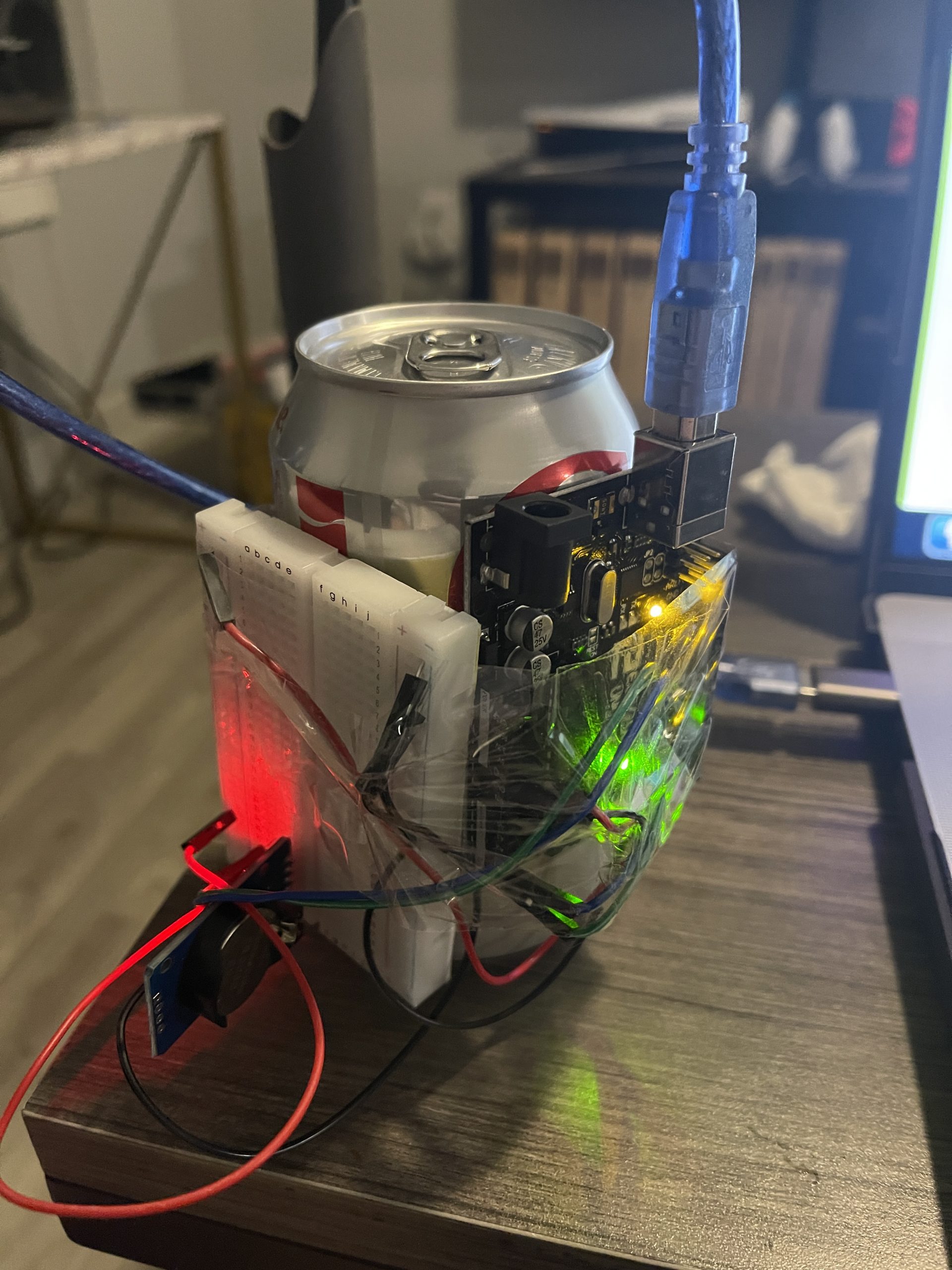
Front view of device
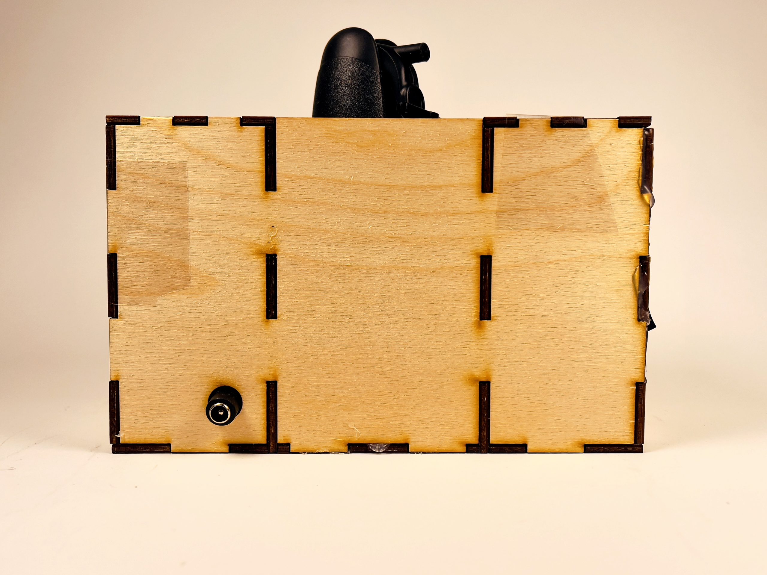
Side view of device
Processing
Key decision point
When I finished working on the servo motor through time control I actually finished the basic work. After that I decided to add buttons to make it easier for the user to operate. I didn’t intend to include these buttons in my earliest preconceptions, but it would result in the inconvenience of having to upload the set time once every time I set the alarm, which is very inconvenient.
I didn’t want to add an LCD screen in my earliest preconceptions, but eventually I thought it would be a good idea to add an LCD screen to visualize the whole process, after all, as an alarm clock, it would be unreasonable for the user not to be able to see the time directly. But this eventually led me to the assembly of the line gave me a lot of trouble.
Process
As the earliest model, I initially wanted to stick everything on a can of compressed air, but this made the device very awkward to use, so the idea was abandoned.
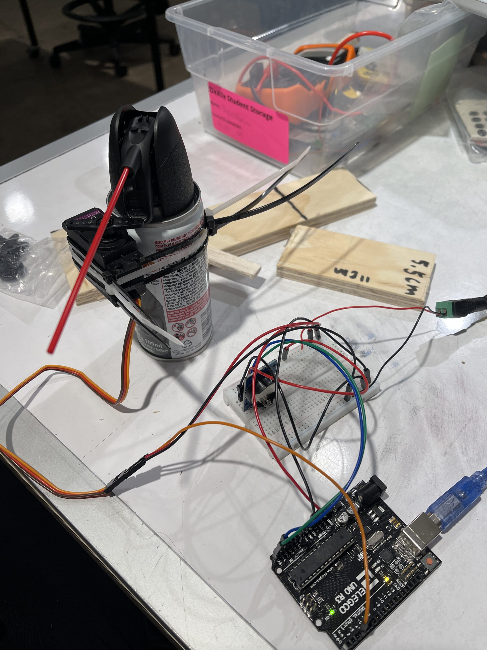
In this image I only decided to stick the servo motor with the canned compressed air. This way the servo motor can directly touch the trigger of the canned air. I used zip ties to keep the servo motor in place on the canned air, and I added a layer of double-sided tape between them to increase friction so the servo motor wouldn’t move around.
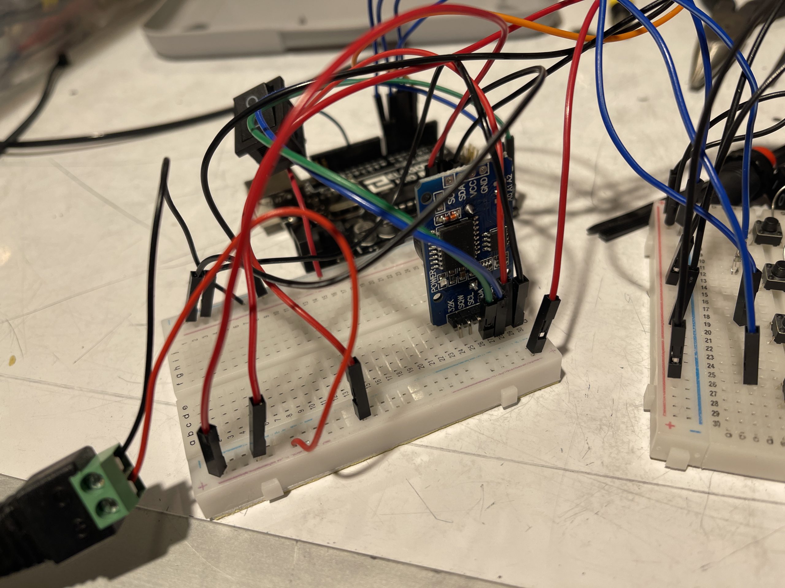
This image shows the Real Time Clock, which reads the current time and runs itself internally, so it keeps the correct time after one code upload. So it becomes the most important component.
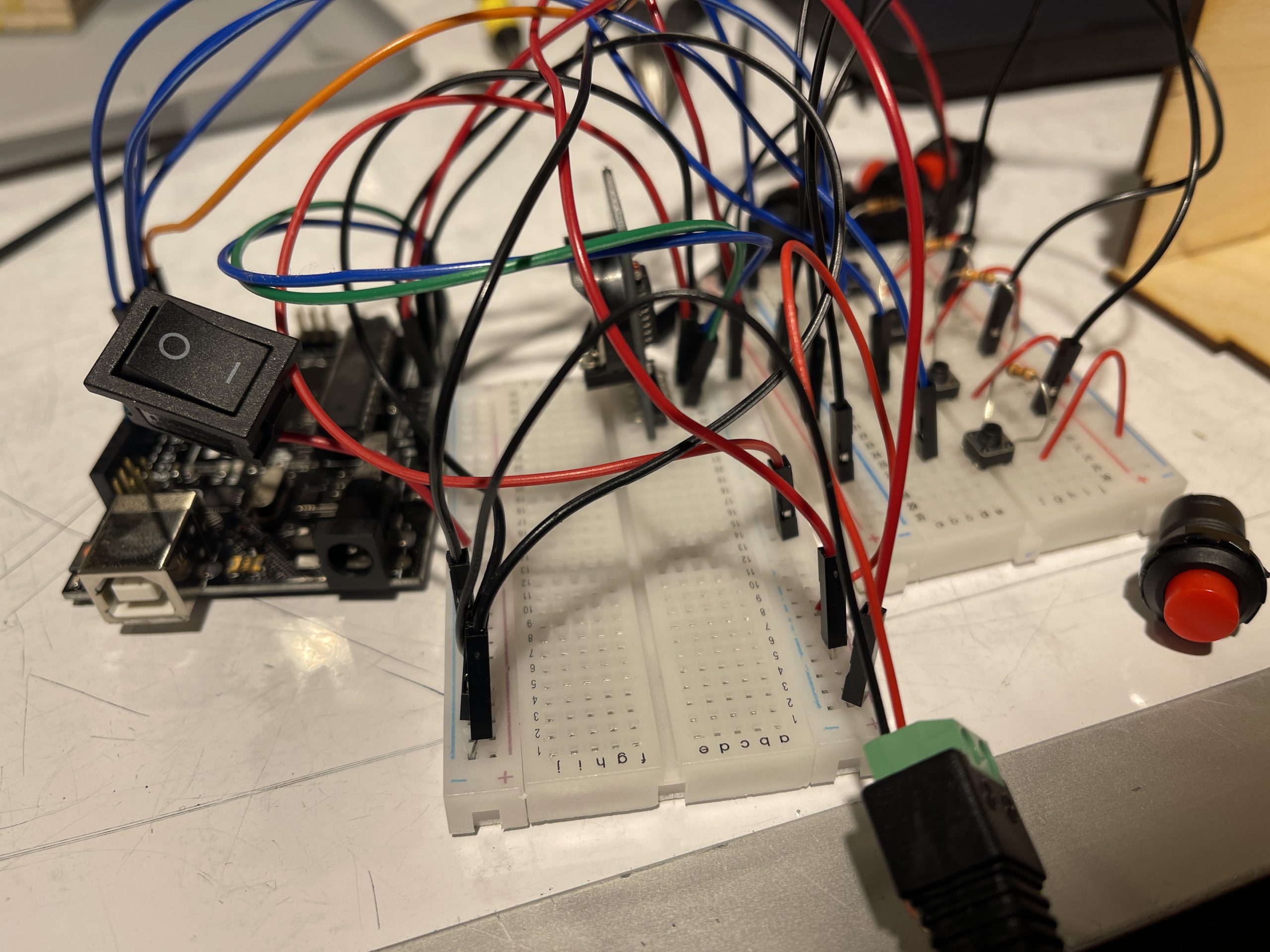
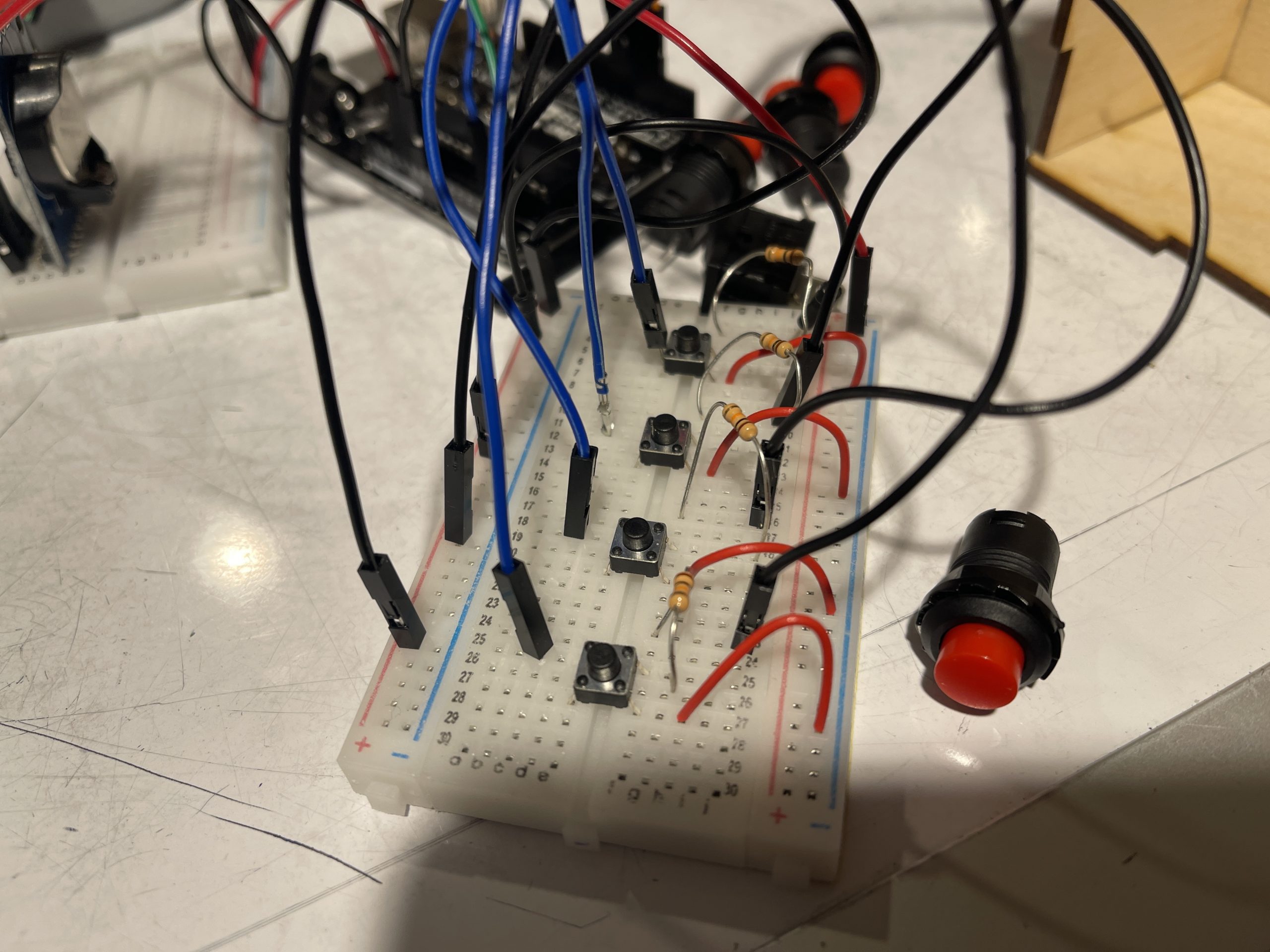
This image shows the earliest prototype of the device, which was assembled into a small model, eventually making rewiring the device the most difficult task. And the original small button had to be replaced with a red button, but the red button had poor contact. So I still think the small button is more suitable for this device.
Discussion:
First we discussed the comments about the classroom, and as I looked through the comments I found that there were no comments with substantive suggestions. So I thought I would respond to the verbal suggestions that were made at the time. There were two points in total, the first was about the model, the model was not designed very well. The cans of air and servo motor are completely exposed, and it would be better to cover them up to keep the user mystified. And the tube used to extend the distance of air injection needs to be fixed in a better way. I couldn’t agree more with these two points, first of all the first point was not envisioned when I designed the model and I think it makes perfect sense. This is really a design flaw that I need to improve. But the second point is also something I had thought about, in my opinion I need a tube that is closer to the material of the water pipe, since this material is soft enough and can be extended while fixing a certain shape.
Going back to my own opinion about my project, I think I am very satisfied with my project, but the result is not 100% satisfying to me. One of the main reasons is that when I should use the red buttons, I can’t set the alarm time accurately with these buttons. The link to it is very unstable due to the soldering. I tried to use smaller buttons but they could not be firmly fixed on the model. So it would be a great success if I could solve this problem. The next point of dissatisfaction is the model, I think the model design has many defects. In addition to not covering the canned air well as mentioned before, I think I designed the model too delicate, which gave me a lot of trouble when lining up the wires. All the wires were messed up which made me struggle a lot during assembly, so a bigger model was necessary. In addition, I also need to design an extra socket on the model to connect the Arduino to the computer, so that it is more convenient to upload.
Through the process of working on this project, I realized that I need to be more attentive in designing models. I don’t think I’m incapable of doing this well, I just think I need more time and more common sense. So I think this project is a very good attempt. Next time I will consider the wiring first and the aesthetics second. Also if I could give my previous self a suggestion, I would tell him that.
In the follow-up I hope to have the opportunity to continue building another iteration of this project. First I will solve the model problem, I will make the model bigger to make the wiring easier, and make the appearance more user-friendly. After that I will figure out how to solve the button problem, I hope there is a better way or I can find a suitable button to solve the poor contact problem. When the two problems are solved I believe the device can really be put into use.
Technical Information:
Code
/*
Project Name: Physical Wake-up Service
Made by Yuxi(Ethan) Xu

- LCD screen display real time and set alarms
- use button to set alarms
- servo motor will be activated when the set time is reached
- servo motor presses the trigger of can of compressed air

Pin Mapping:
3: Servo motor
4-7: Button Power In 1-4
12: Switch Power In

Some of the code is adapted from the following sources
- DS3231 RTC (Real Time Clock) Interfacing with Arduino to build DIY Digital Clock, Author: Harshil Patel
- ArduinoGetStarted.com: Arduino - Switch
*/

#include <RTClib.h>
#include <Wire.h>
#include <Servo.h>
#include <ezButton.h>
#include <LiquidCrystal_I2C.h>

LiquidCrystal_I2C screen(0X27, 16, 2);
ezButton toggleSwitch(12);
RTC_DS3231 rtc;

//Servo motor
const int SERVOPIN = 3;
Servo Servo1;

//Buttons
const int buttonPin1 = 4;
const int buttonPin2 = 5;
const int buttonPin3 = 6;
const int buttonPin4 = 7;
int PbuttonState1;
int PbuttonState2;
int PbuttonState3;
int PbuttonState4;
int buttonState1;
int buttonState2;
int buttonState3;
int buttonState4;

//Alarm clock
int alarmhr;
int alarmmin;
int h;
int m;
char t[32];

void setup() {
  Serial.begin(9600);
  Wire.begin();
  rtc.begin();
  Servo1.attach(SERVOPIN);
  toggleSwitch.setDebounceTime(50);

  pinMode(buttonPin1, INPUT);
  pinMode(buttonPin2, INPUT);
  pinMode(buttonPin3, INPUT);
  pinMode(buttonPin4, INPUT);

  rtc.adjust(DateTime(F(__DATE__),F(__TIME__))); //adjust Real Time Clock to current time (You can delete it after uploading it once)

  screen.init();
  screen.backlight();
}

void loop() {

  //Real Time Clock setup:
  DateTime now = rtc.now();
  sprintf(t, "%02d:%02d:%02d %02d/%02d/%02d", now.hour(), now.minute(), now.second(), now.day(), now.month(), now.year());
  h=now.hour();
  m=now.minute();

  //Switch setup:
  toggleSwitch.loop();
  if (toggleSwitch.isPressed()){
    Serial.println("The switch: OFF -> ON");
  }
  if (toggleSwitch.isReleased()){
    Serial.println("The switch: ON -> OFF");
  }
  int state = toggleSwitch.getState();

  //LCD setup:
  if (state == LOW){
    Serial.print(F("Date/Time: "));
    Serial.println(t);

    //Print "Time/Date: " and Real Time Clock on LCD
    screen.home();
    screen.print(F("Time/Date: "));
    screen.setCursor(0, 1);
    screen.print(t);
  }
  else{
    //Print "SetAlarmHr/Min: " and "SetAlarmHr/Min: " on LCD
    Serial.print("SetAlarmHr/Min: ");
    screen.home();
    screen.print("SetAlarmHr/Min: ");

    //Button setup:
    PbuttonState1 = buttonState1;
    PbuttonState2 = buttonState2;
    PbuttonState3 = buttonState3;
    PbuttonState4 = buttonState4;

    //Read state of button
    buttonState1 = digitalRead(buttonPin1);
    buttonState2 = digitalRead(buttonPin2);
    buttonState3 = digitalRead(buttonPin3);
    buttonState4 = digitalRead(buttonPin4);

    //Set hours and minutes when pressed button
    if(buttonState1 == HIGH && PbuttonState1 == LOW){
      alarmhr += 1;
    }
    if(buttonState2 == HIGH && PbuttonState2 == LOW){
      alarmhr += 10;
    }
    if(buttonState3 == HIGH && PbuttonState3 == LOW){
      alarmmin += 1;
    }
    if(buttonState4 == HIGH && PbuttonState4 == LOW){
      alarmmin += 10;
    }

//Print set alarm time
screen.clear();
    Serial.println(alarmhr);
    Serial.println(alarmmin);
    screen.setCursor(0, 1);
    screen.print(alarmhr);
    screen.setCursor(3, 1);
    screen.print(alarmmin);

    //Servo motor works according to the time set by the alarm clock
    if((h==alarmhr) && (m==alarmmin)) {
      Servo1.write(175);
      delay(300);
      Servo1.write(90);
      delay(300);
    }
  }
}