
[62-362] Activating the Body | Project 1: Gates | Fall 2019 | Alex Lin
Approach
Approach to the Project
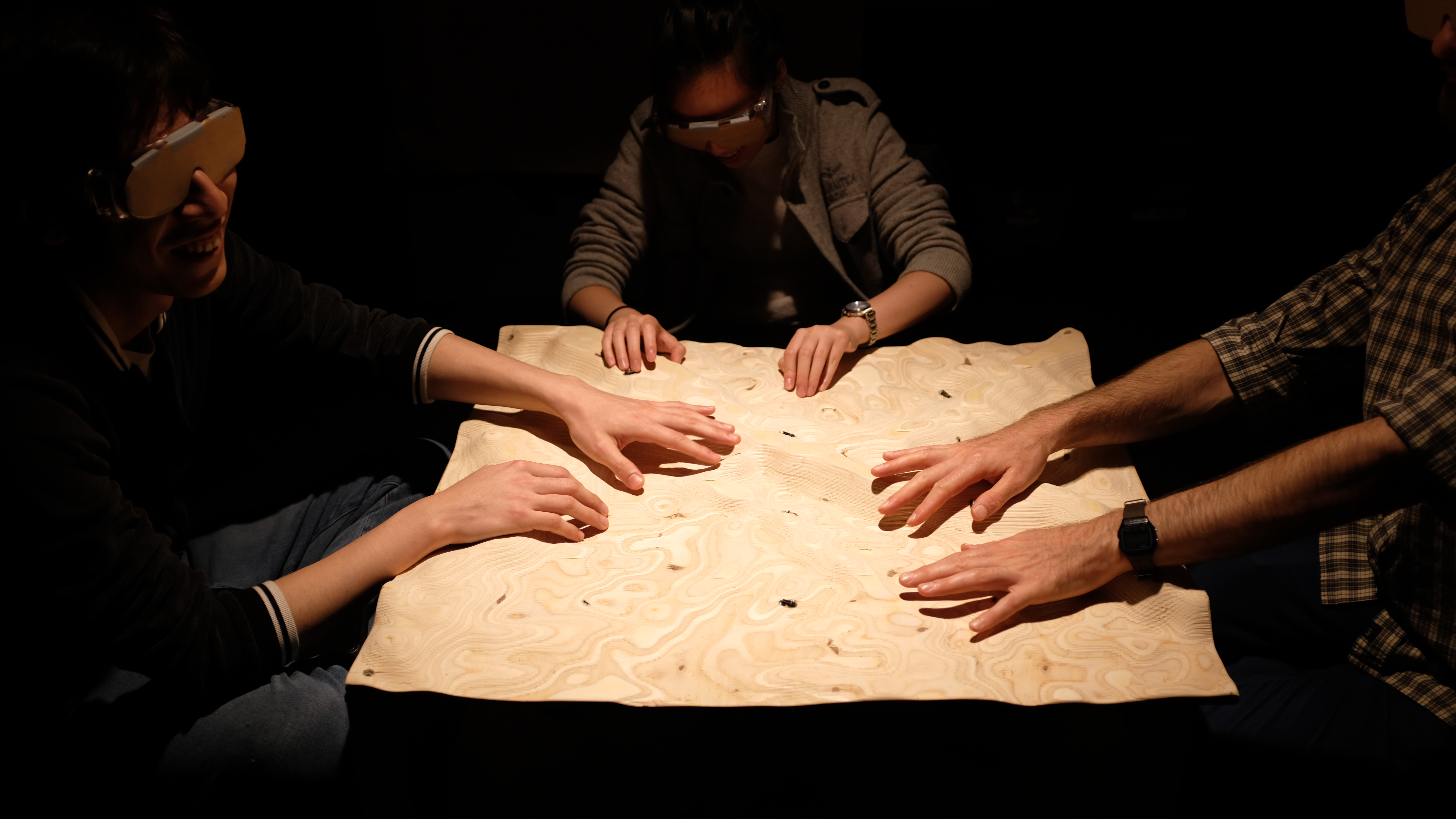
Users “Climbing” 01
Users Exploring the Topography of the Table
Users “Climbing” 02
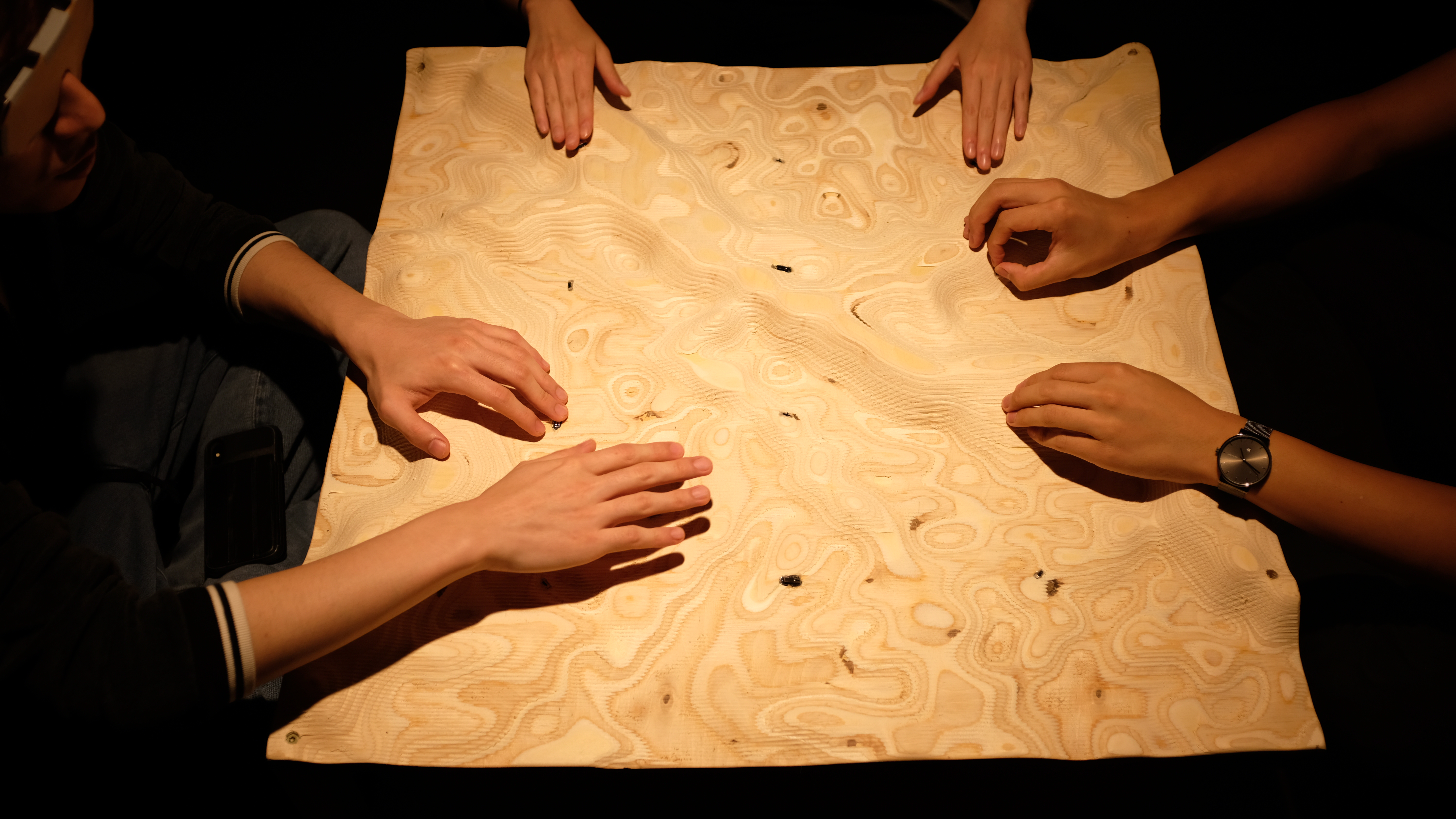
Users Navigating and Testing Switches
Users “Climbing” 03
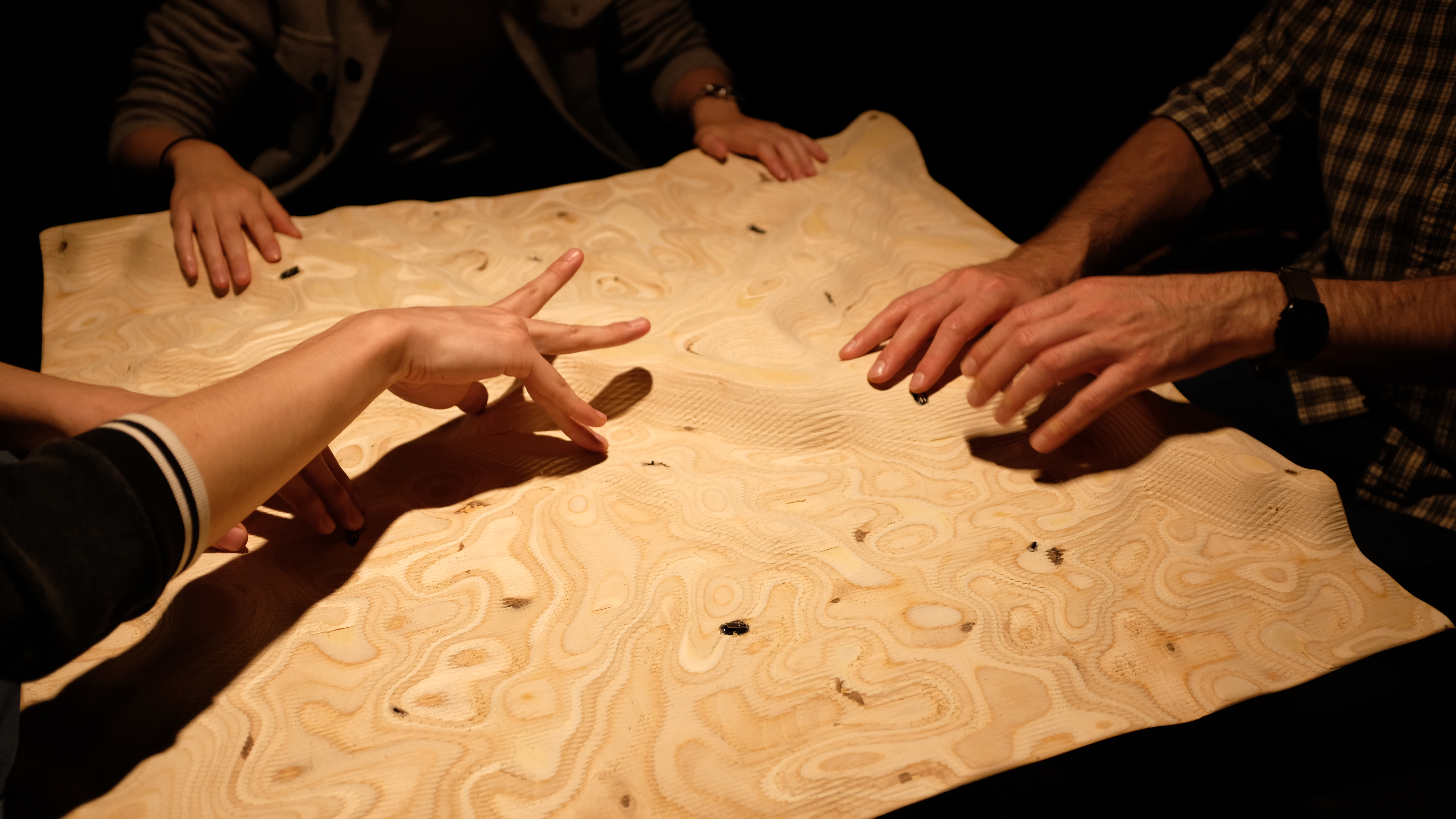
Users’ Dancing Fingers
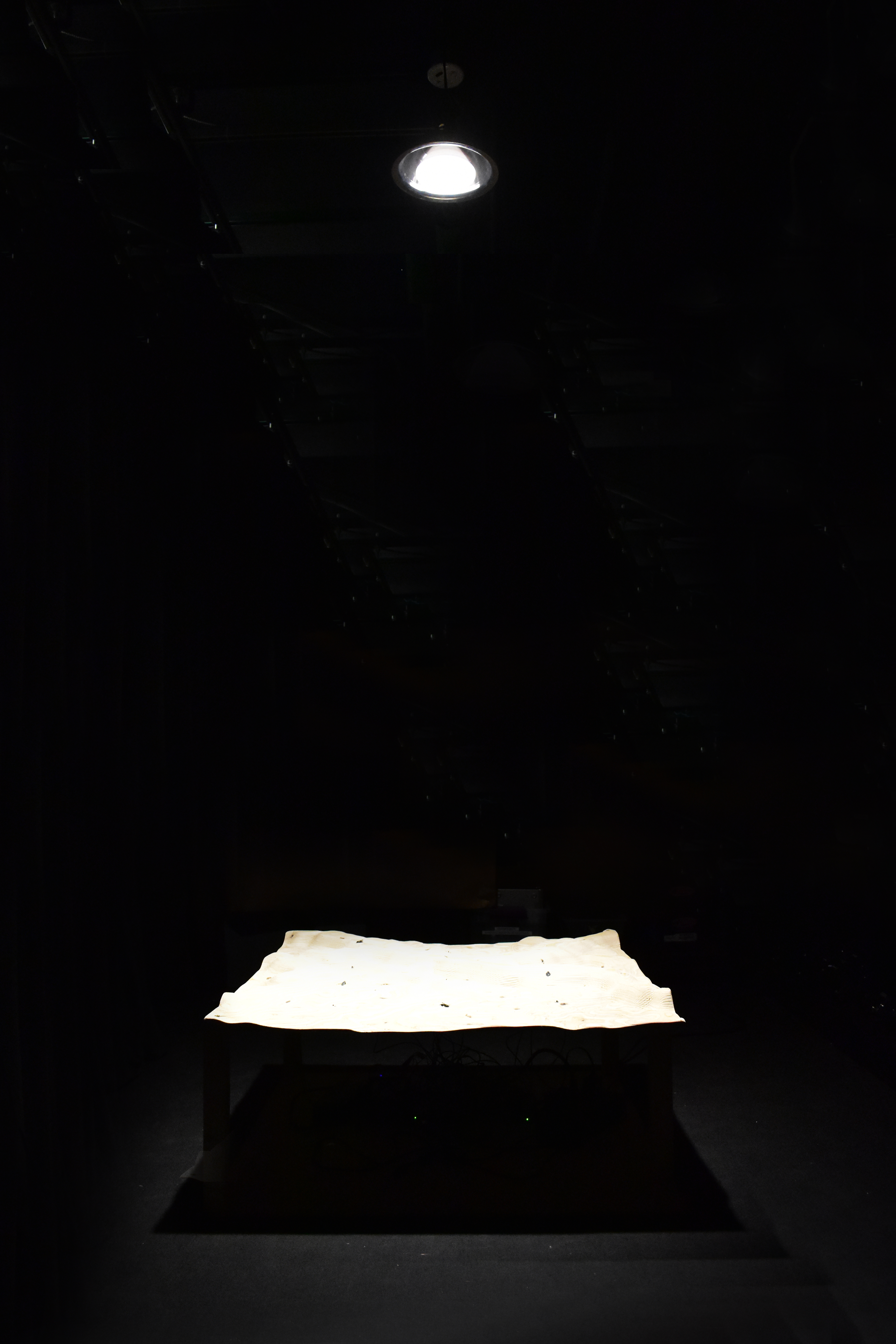
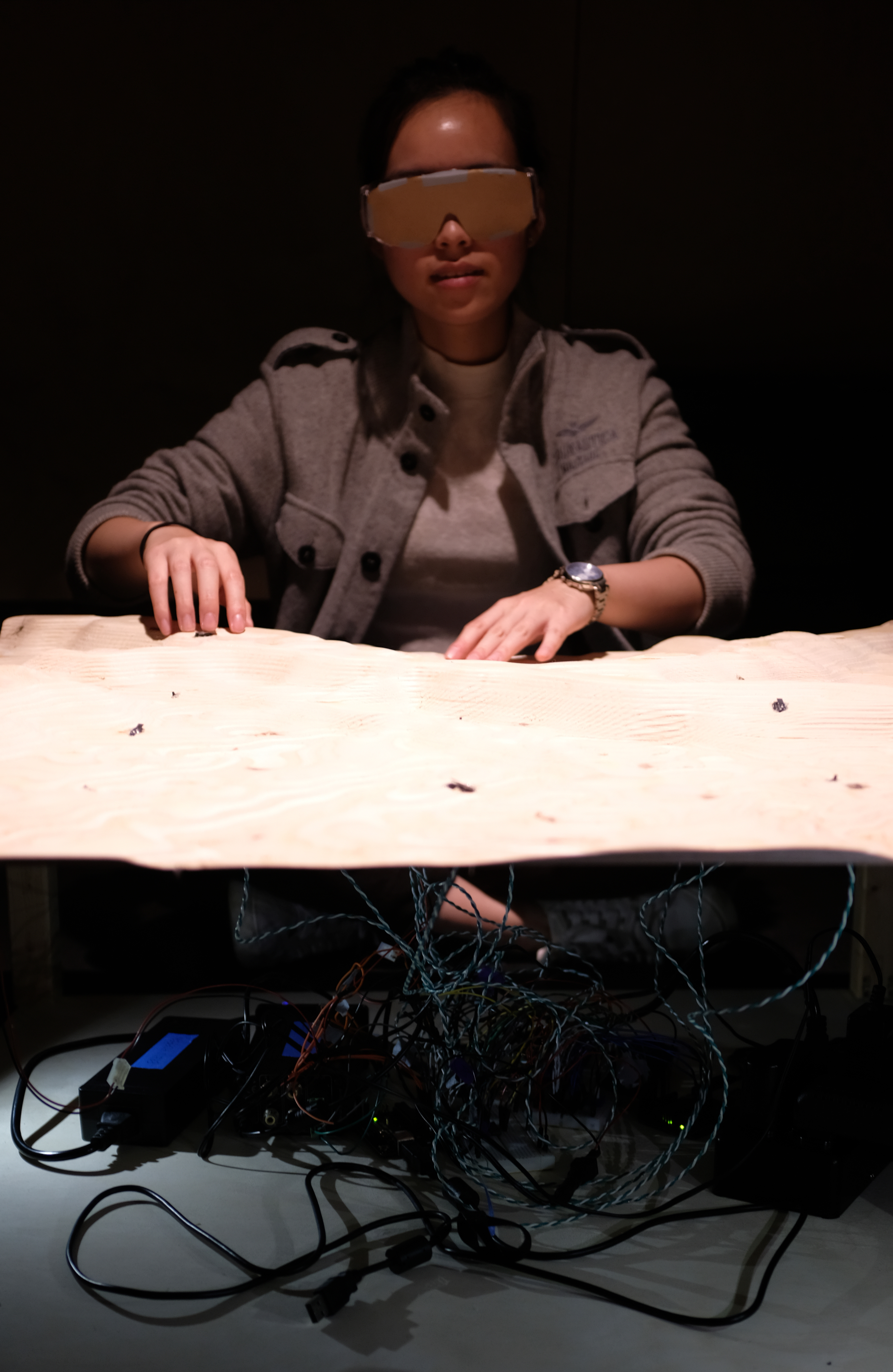
Climbing Table In-Use
Climbing Demonstration

Close Up of How Switches Are Embedded
Embedded Lever and Switch
Blindfold
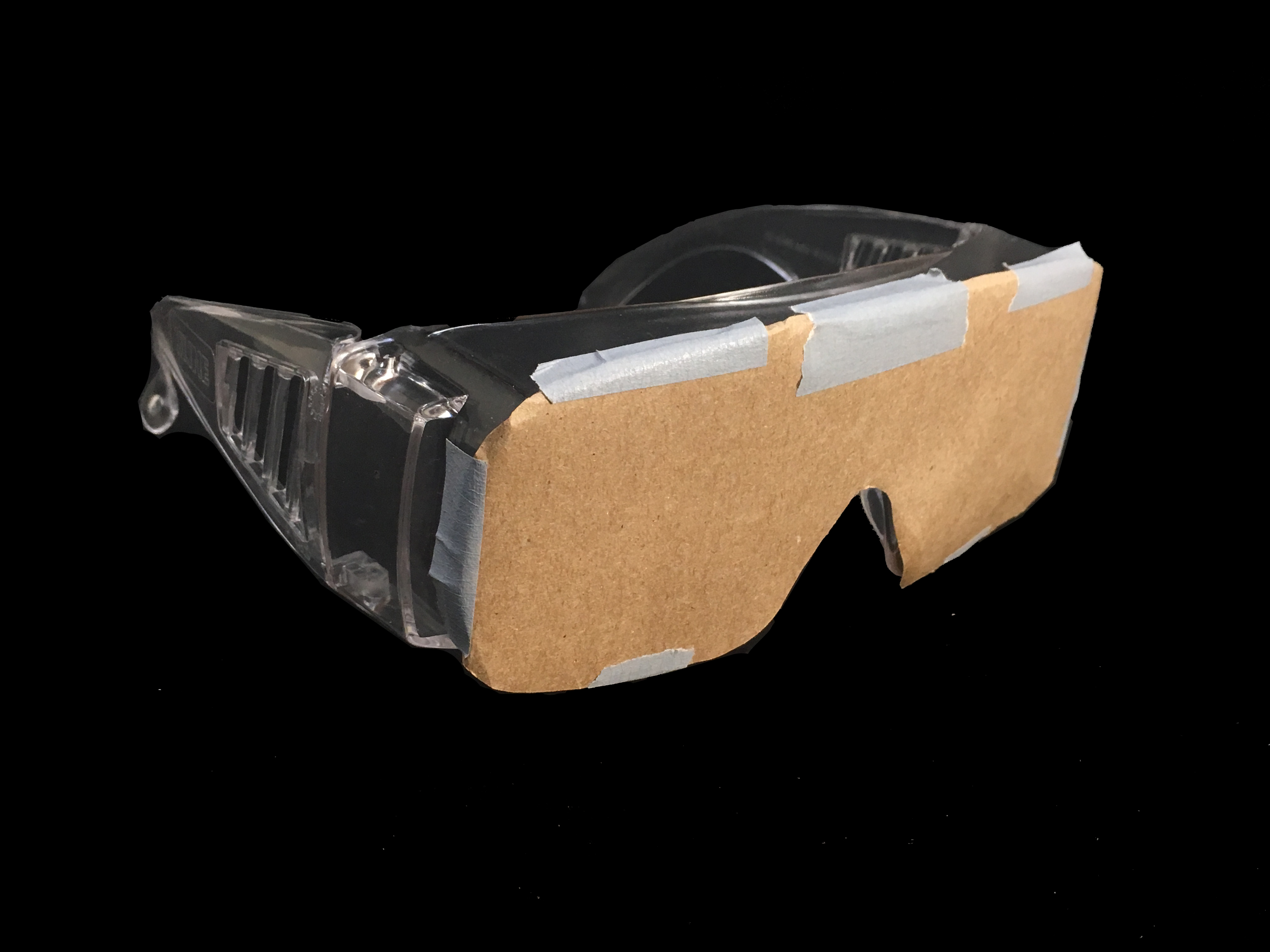
Simple Perspective of the Blindfold
Inner Workings of the Climbing Table
Perspective Showing the Electronics that Make the Climbing Table Work
Description
Abstract Description
A table has little switches on it. People who can’t see sit around the table and play with the switches. When the right pairs of switches are pushed and switched on, the people at the table hear a sound. When other groups of switches are pushed, the table shakes.
Narrative Description
The Climbing Table is an interactive installation which invites up to four people to sit at a short table and to blindly explore a topographic landscape of CNC-milled plywood that features embedded buttons and switches. By pressing buttons and turning on switches in the correct combination, sounds are emitted from the table which ultimately play a chord. The concept strives to bring people close together and portray the individual unintentional and intentional actions that contribute to a larger effort. Ultimately, the project strives to represent the complexity of working with others and navigating tasks with a lens that magnifies the interaction and connection between people.
Process Images
Initial Concept Sketches:
The initial idea was to have a larger table with embedded LEDs, speakers, and vibration speakers. In developing the concept, various aspects of the idea were tweaked to address ideas of teamwork and group dynamics. For example, the proportions of the table were changed to a square in plan so that everyone had equal access to the buttons, which were placed in an array format.
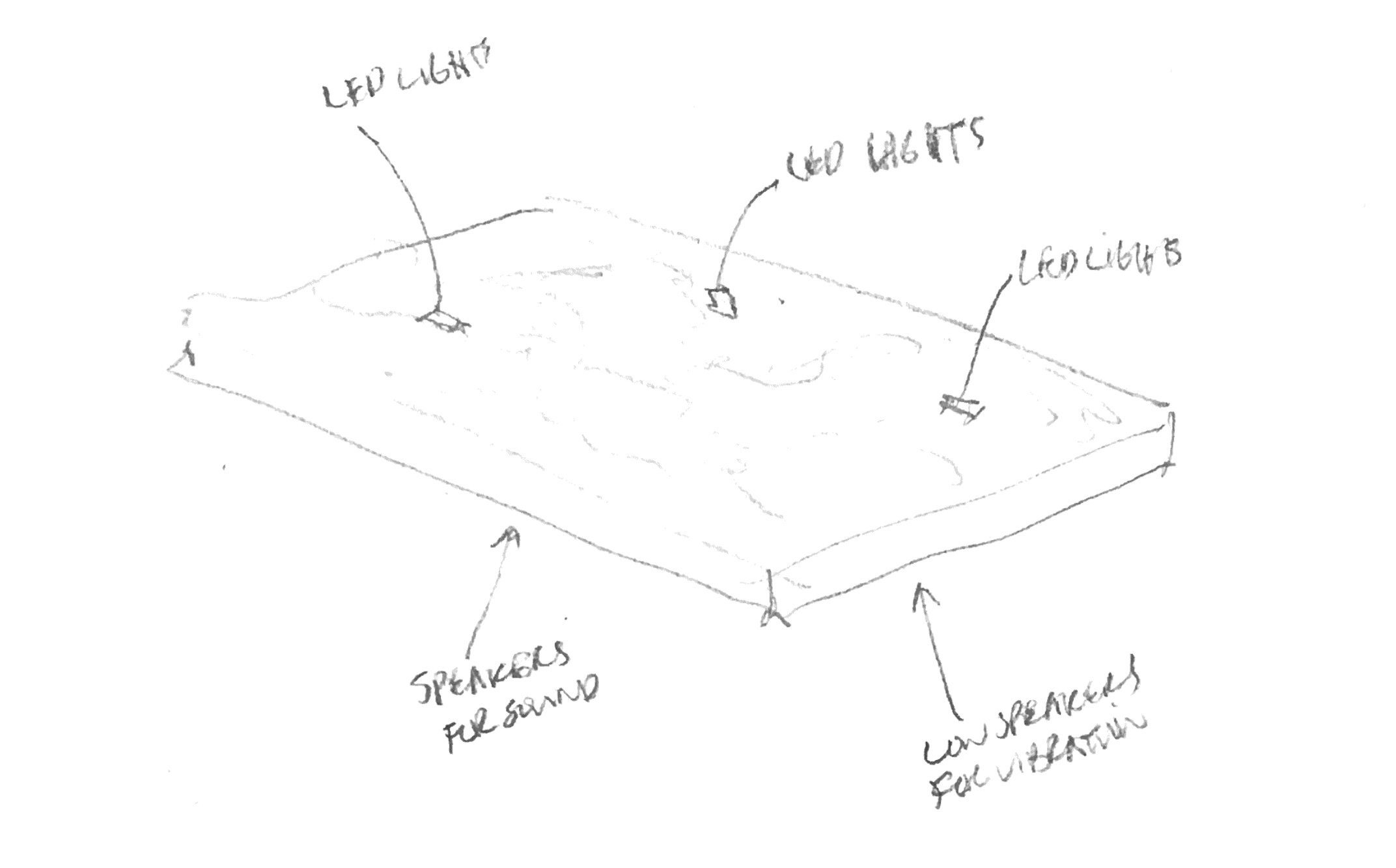
Axonometric Sketch of Outputs
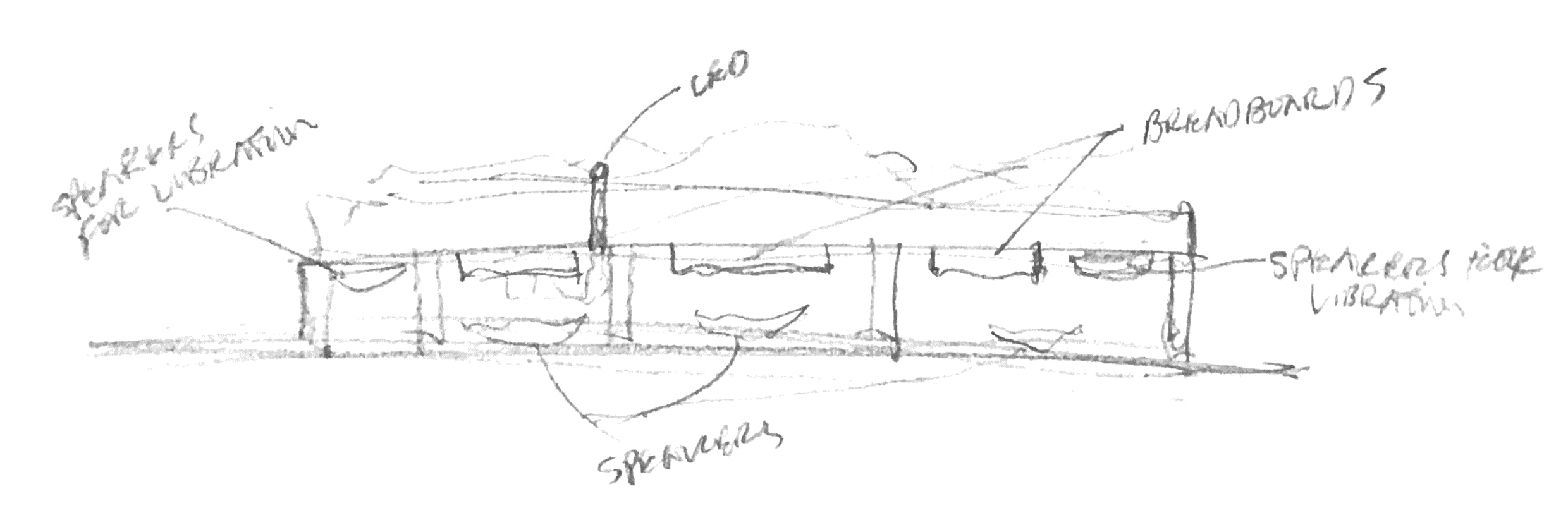
Elevation of Placement/Planning of Outputs
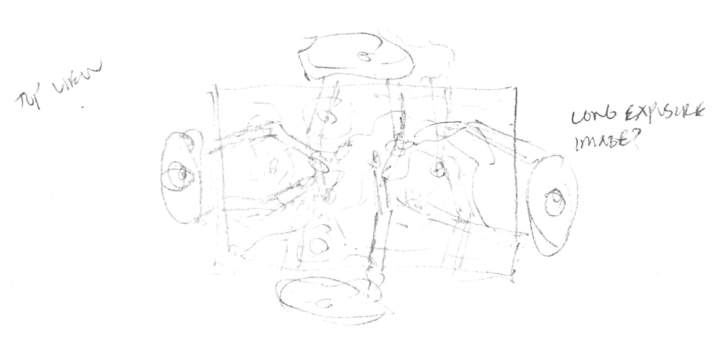
Plan View of Envisioned Interaction
CNC Regrets:
To make the cost of buying materials for the table cheaper, I laminated 8 sheets of 6 mm thick plywood, but the glue job was not perfect. The material warped a bit because I just clamped the material together after applying glue (should have used vacuum table). As a result, due to the intricacy of the topography that I modeled, some small chunks of plywood were detached during the CNC job. The detail in the model also caused the CNC job to take over 4 hours. While the process would have been faster and more efficient using foam, the ultimate texture, look, and feel of the table was definitely augmented by the material properties of the plywood.
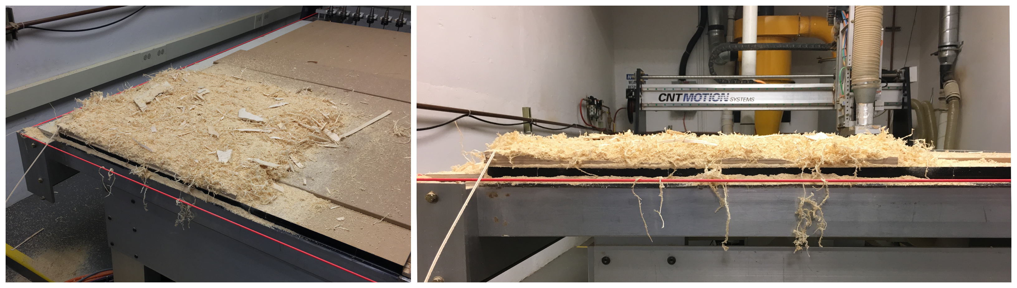
Collage of Table Post-CNCing
Soldering Switches:
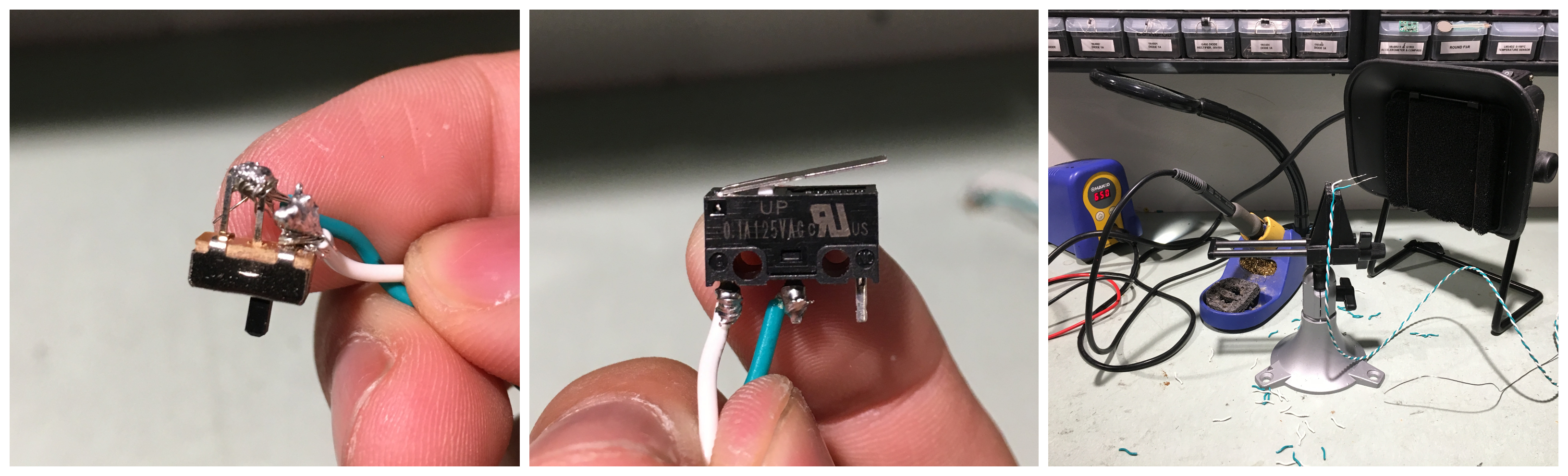
Collage of Soldering Switches
I ended up deciding to use 12 switches, 6 of the smaller switches that can remain on or off and 6 of the slightly larger push lever switches that function as buttons. The process of soldering everything together as one can imagine was difficult for someone who had not soldered before, but it worked out in the end. During this process, I heavily considered using 12 of the lever switches for convenience sake, however, I was interested in how the more continuous switches would change the interactions between users and how people’s decisions could make or break whether or not a speaker worked, so I kept both types.
Table Legs:
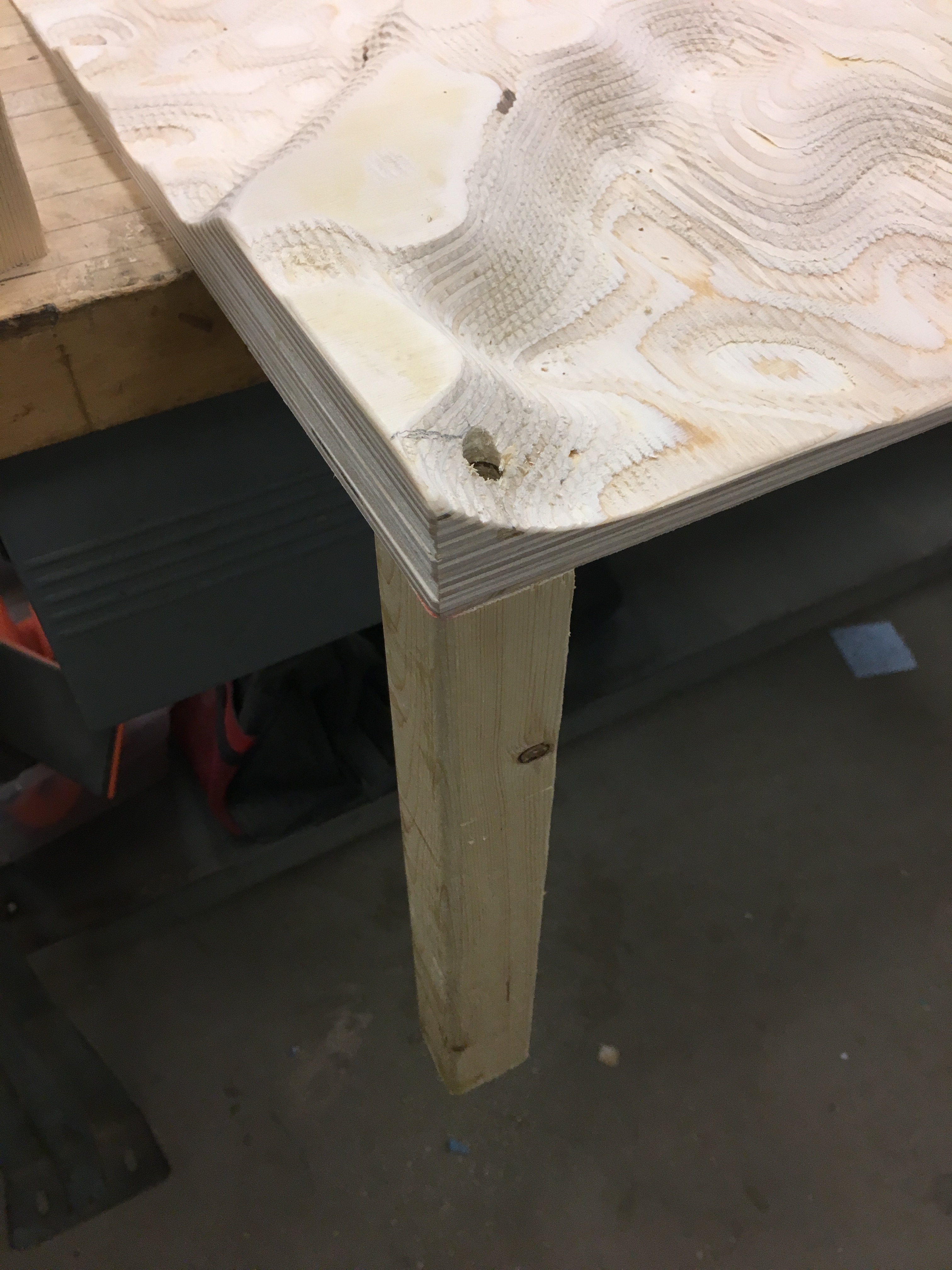
Detail of Leg Secured to the Table
Although ideally the table legs would have been more seamlessly integrated into the table in a fashion that didn’t penetrate through the topographic surface, in the interest of time and focusing on other aspects of the design that were more significant, I decided to use a few screws to attach the surface to the 2X2’s that I had chopped to size. I was worried about stability, but the legs worked really well.
Wiring:
As one can imagine, with 12 switches, 8 speakers, 2 Arduinos, and a bunch of wires can get really messy. There were times when I had to use tape to bundle pairs of wires together to make sure I could navigate through the jungle of wires and electronics. It ended up working out, although it would have been better to test everything at a singular scale to make sure that everything was wired correctly and the code worked before scaling up.
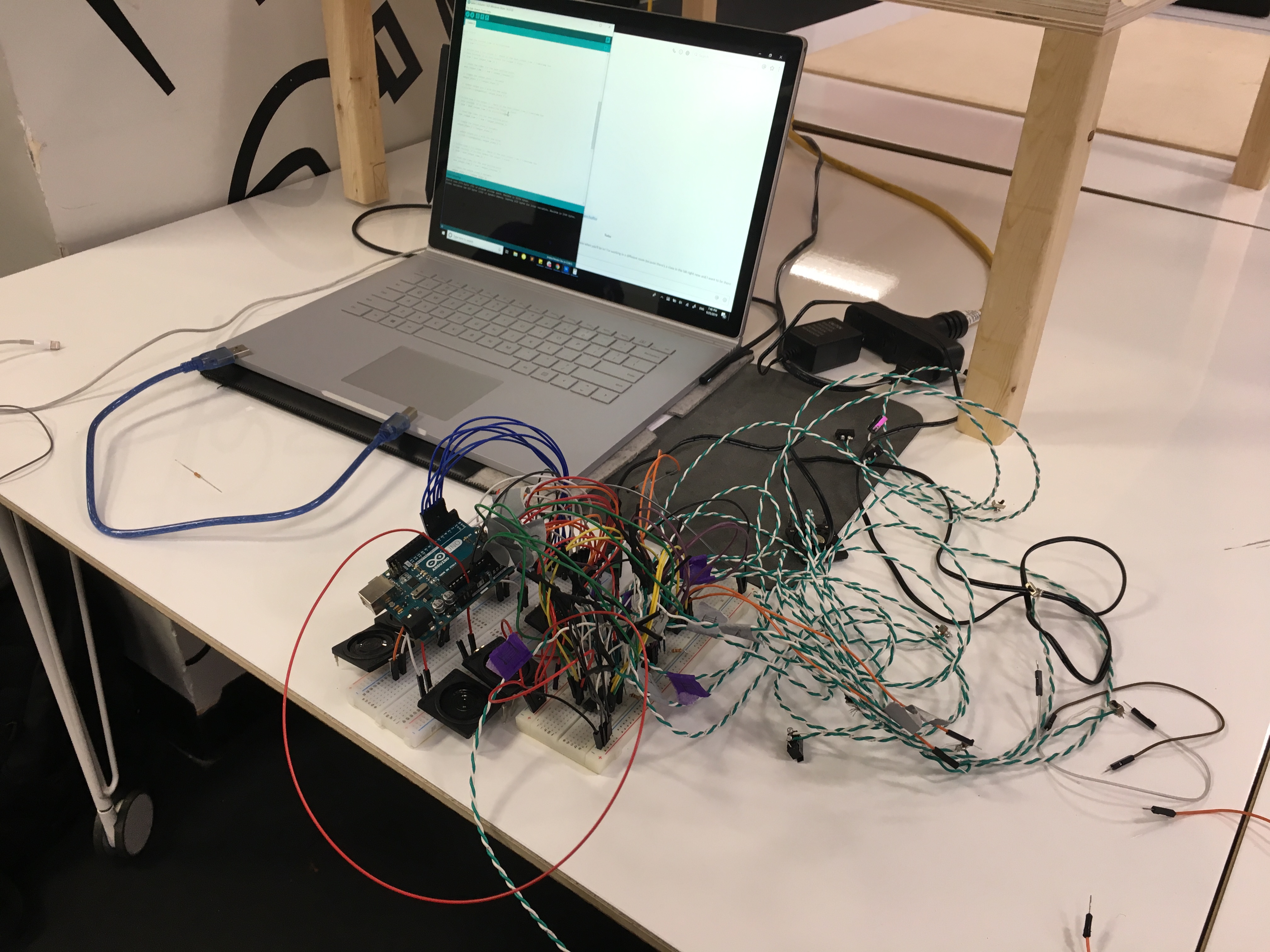
Process Perspective of Computer and Wiring Progress
Process Reflection
I thought I knew what I was getting into when I decided to take on this concept. The digital fabrication would be a lengthy process, the shear quantity of switches would make a simple logic diagram very complex, and the integration of the two systems would be a rough one. I definitely underestimated how much work it would take to execute on it though. The modeling and CNC-ing of the table wasn’t actually that difficult, but access to machines and technology struggles in general definitely pushed the project back. The sanding and post processing of the table was then expedited to make time for the technology to come in. I wasn’t able to spend as much time as I would have liked, but it was fairly straightforward and there were other things that were more pressing.
When it came to technology, this was where I learned the most lessons. Not only in regards to the wiring of the electronics and coding the Arduino, but also general lessons to carry forward. I learned that having everything working electronically separately from its housing is great, but then integrating it into the housing becomes a very fragile and frustrating process. I think in the future, I should try and start small and slowly build up the projects along with the technology, although perhaps more cumbersome, by working on the digital fabrication and electronic parts in parallel, I would have foreseen issues that came up like how I planned on embedding the switches or how I would house the tangled mess of wires and electronics. I also learned about general tips and tricks about wiring and electronics to put more effort upfront and have an easier time troubleshooting later on. Knowledge-wise, I learned a lot about how the logic chips work and got to try out some cool things which was great!
Looking forward, I was really inspired by other people’s projects that integrated more full body activation of its users. I also felt that my project was more of a social experiment and lacked the force of a strong message/theoretical underpinning. Moving forward, I want to inject more meaning and purpose into my projects, so that they are more impactful experiences and bring a different perspective on a complex issue. Lastly, in regards to creatively using electronics to make cool experiences, I want to strive to do more with less. I got really caught up in having a lot of options, more buttons, and more switches which ended up making the project difficult to pull off (although it did add more things to find and explore). I think if I had used maybe 4 switches, one for each person, and had embedded AND, OR, NAND, XOR, etc. logic chips based on combinations of the switches, that it could have been a much more refined project that would be more interesting and playful.
Logic Schematic
Proposed:
The proposed logic schematic included more vibration as well as light for each switch. As the design began to progress, I found that the LEDs weren’t making sense as a concept unless they were strong enough to produce sensible heat and so that eventually was taken out. The vibration was scaled down as well due to lack of time and planning on testing various vibration methods.
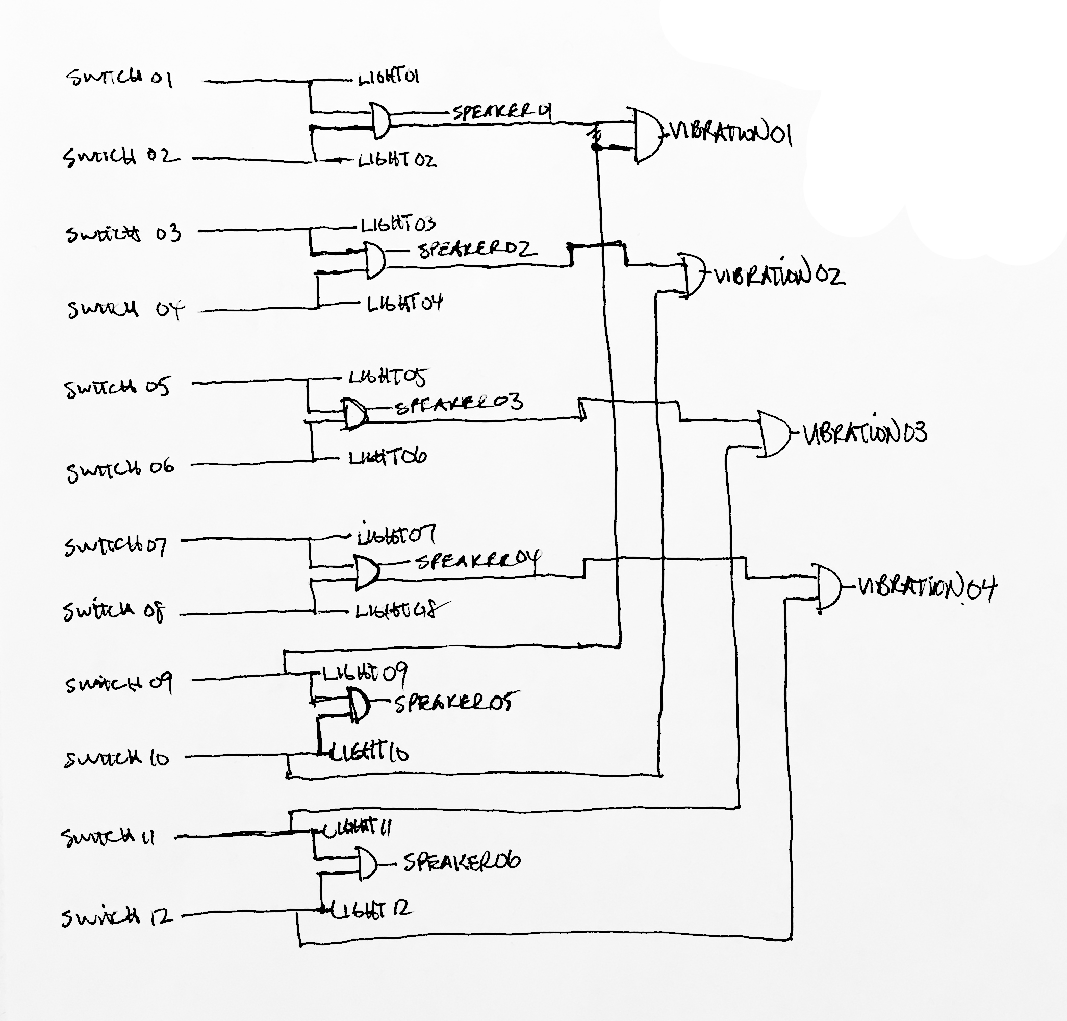
Process Logic Schematic
Final:
The final logic schematic shows what was left at the end. The vibration was intended to be controlled by OR logic instead of AND due to constraints of vibration speakers, however some errors in either code or understanding of sending signals to the speakers used for vibration made it not function in reality. The OR logic was not applied through chip though, and was through Arduino programming/code.
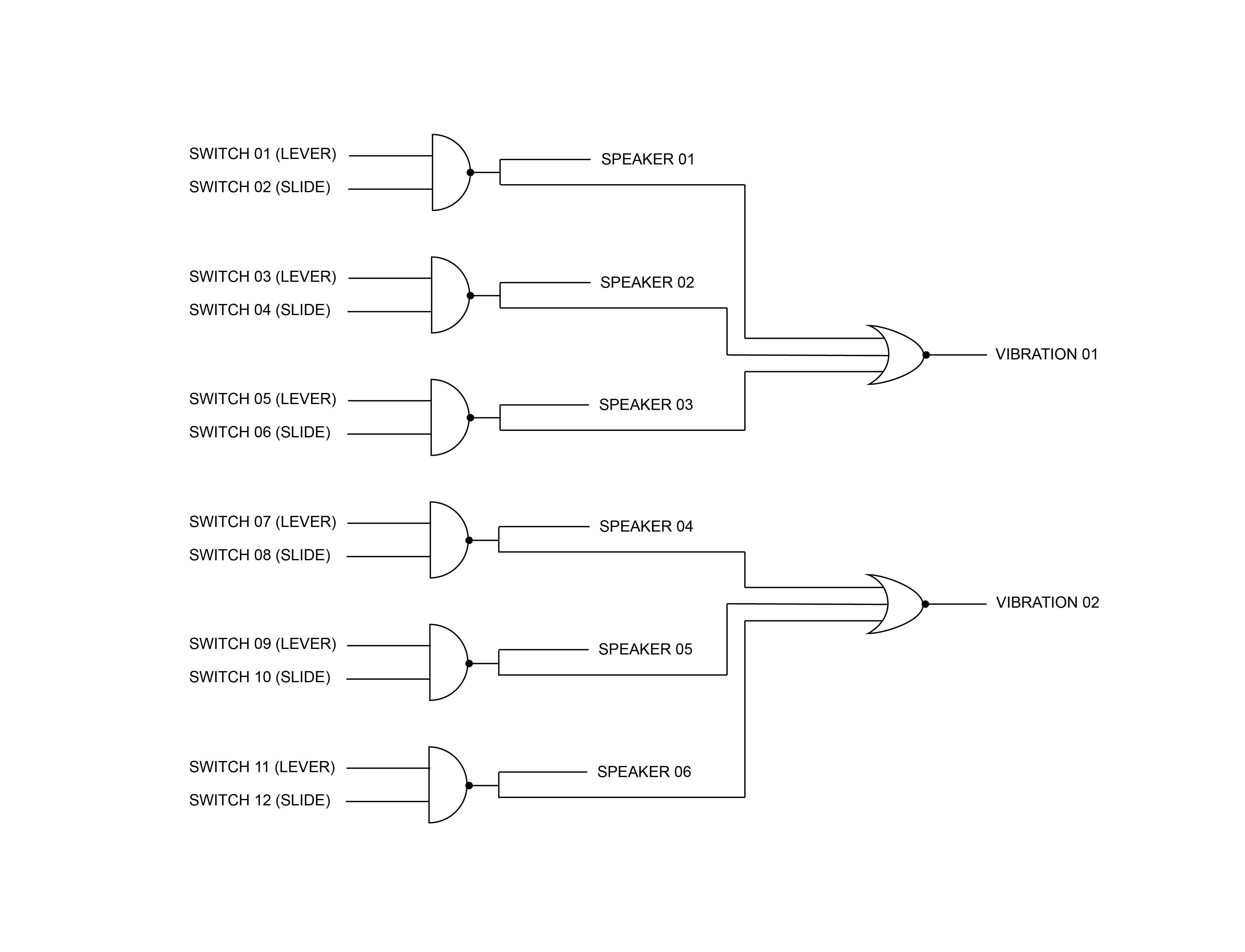
Final Logic Schematic
Primary Arduino Code (Speakers)
//Climbing Table by Alex Lin
//This code inputs signals from various input pins, checks for HIGH or LOW,
//then sends a signal to a speaker if the input is HIGH. This code is sourced
//from the following site: https://courses.ideate.cmu.edu/16-223/f2019/text/exercises/Arduino/event-loop-programming/event-loop-programming.html#exercise-event-loop-programming
//and was developed by Professor Garth Zeglin. It allows for multiple speakers
//to be controlled by one Arduino board.
//The pins are matched in numerical order (A0 > 2, A1 > 3, etc.)

#define outputPin1 7
#define outputPin2 2
#define outputPin3 3
#define outputPin4 4
#define outputPin5 5
#define outputPin6 6

#define inputPin1 A0
#define inputPin2 A1
#define inputPin3 A2
#define inputPin4 A3
#define inputPin5 A4
#define inputPin6 A5

long next_output_time_1 = 0;        // timestamp in microseconds for when next to update output 1
long next_output_time_2 = 0;        // timestamp in microseconds for when next to update output 2
long next_output_time_3 = 0;        // timestamp in microseconds for when next to update output 1
long next_output_time_4 = 0;        // timestamp in microseconds for when next to update output 2
long next_output_time_5 = 0;        // timestamp in microseconds for when next to update output 1
long next_output_time_6 = 0;        // timestamp in microseconds for when next to update output 2

long output_interval_1 = 1012;       // B interval in microseconds between output 1 updates
long output_interval_2 = 1351;       // G interval in microseconds between output 2 updates
long output_interval_3 = 851;       // interval in microseconds between output 1 updates
long output_interval_4 = 2551;       // interval in microseconds between output 2 updates
long output_interval_5 = 2025;       // interval in microseconds between output 1 updates
long output_interval_6 = 1703;       // interval in microseconds between output 2 updates

int output_state_1 = LOW;           // current state of output 1
int output_state_2 = LOW;           // current state of output 2
int output_state_3 = LOW;           // current state of output 1
int output_state_4 = LOW;           // current state of output 2
int output_state_5 = LOW;           // current state of output 1
int output_state_6 = LOW;           // current state of output 2

void setup()
{
  Serial.begin(9600); // initialize serial communications

  //Setting up pins

  pinMode(outputPin1,OUTPUT);
  pinMode(outputPin2,OUTPUT);
  pinMode(outputPin3,OUTPUT);
  pinMode(outputPin4,OUTPUT);
  pinMode(outputPin5,OUTPUT);
  pinMode(outputPin6,OUTPUT);

  pinMode(inputPin1,INPUT);
  pinMode(inputPin2,INPUT);
  pinMode(inputPin3,INPUT);
  pinMode(inputPin4,INPUT);
  pinMode(inputPin5,INPUT);
  pinMode(inputPin6,INPUT);
}

void loop()
{
  // read the current time in microseconds
  long now = micros();

  Serial.println(analogRead(A0));

  // Polled task 1 for output 1.  Check if the next_output_time_1 timestamp has
  // been reached; if so then update the output 1 state.
  if (now > next_output_time_1 && analogRead(A0) > 0) {

    // reset the timer for the next polling point
    next_output_time_1 = now + output_interval_1;

    // toggle the output_state_1 variable
    output_state_1 = !output_state_1;

    // update output pin 1 with the new value
    digitalWrite(outputPin1, output_state_1 );
  }

  // Polled task 2 for output 2.  Check if the next_output_time_2 timestamp has
  // been reached; if so then update the output 2 state.
  if (now > next_output_time_2 && analogRead(A1) > 0) {

    // reset the timer for the next polling point
    next_output_time_2 = now + output_interval_2;

    // toggle the output_state_2 variable
    output_state_2 = !output_state_2;

    // update output pin 2 with the new value
    digitalWrite(outputPin2, output_state_2);
  }

  // Polled task 3 for output 3.  Check if the next_output_time_3 timestamp has
  // been reached; if so then update the output 3 state.
  if (now > next_output_time_3 && analogRead(A2) > 0) {

    // reset the timer for the next polling point
    next_output_time_3 = now + output_interval_3;

    // toggle the output_state_2 variable
    output_state_3 = !output_state_3;

    // update output pin 3 with the new value
    digitalWrite( outputPin3, output_state_3);
  }

    // Polled task 4 for output 4.  Check if the next_output_time_4 timestamp has
  // been reached; if so then update the output 4 state.
  if (now > next_output_time_4 && analogRead(A3) > 0) {

    // reset the timer for the next polling point
    next_output_time_4 = now + output_interval_4;

    // toggle the output_state_2 variable
    output_state_4 = !output_state_4;

    // update output pin 4 with the new value
    digitalWrite( outputPin4, output_state_4);
  }

    // Polled task 5 for output 5.  Check if the next_output_time_5 timestamp has
  // been reached; if so then update the output 5 state.
  if (now > next_output_time_5 && analogRead(A4) > 0) {

    // reset the timer for the next polling point
    next_output_time_5 = now + output_interval_5;

    // toggle the output_state_2 variable
    output_state_5 = !output_state_5;

    // update output pin 3 with the new value
    digitalWrite( outputPin5, output_state_5);
  }

    // Polled task 3 for output 3.  Check if the next_output_time_3 timestamp has
  // been reached; if so then update the output 3 state.
  if (now > next_output_time_6 && analogRead(A5) > 0) {

    // reset the timer for the next polling point
    next_output_time_6 = now + output_interval_6;

    // toggle the output_state_2 variable
    output_state_6 = !output_state_6;

    // update output pin 3 with the new value
    digitalWrite( outputPin6, output_state_6);
  }
}
Secondary Arduino Code (Vibration)
//Climbing Table by Alex Lin
//This code inputs signals from various input pins, checks for HIGH or LOW,
//then sends a signal to a vibration speaker if the input is HIGH. This code is sourced
//from the following site: https://courses.ideate.cmu.edu/16-223/f2019/text/exercises/Arduino/event-loop-programming/event-loop-programming.html#exercise-event-loop-programming
//and was developed by Professor Garth Zeglin. It allows for multiple vibration speakers
//to be controlled by one Arduino board.
//A0 and A1 are matched to outputPin1 and A2 and A3 are matched to outputPin2

#define outputPin1 5
#define outputPin2 10

long next_output_time_1 = 0;        // timestamp in microseconds for when next to update output 1
long next_output_time_2 = 0;        // timestamp in microseconds for when next to update output 2

long output_interval_1 = 50000;       // interval in microseconds between output 1 updates
long output_interval_2 = 45000;       // interval in microseconds between output 2 updates

int output_state_1 = LOW;           // current state of output 1
int output_state_2 = LOW;           // current state of output 2

void setup()
{
  Serial.begin(9600);

  pinMode(outputPin1,OUTPUT);
  pinMode(outputPin2,OUTPUT);

  pinMode(A0,INPUT);
  pinMode(A1,INPUT);
  pinMode(A2,INPUT);
  pinMode(A3,INPUT);
}

void loop()
{
  // read the current time in microseconds
  long now = micros();

  Serial.println(analogRead(A0));

  // Polled task 1 for output 1.  Check if the next_output_time_1 timestamp has
  // been reached; if so then update the output 1 state.
  if (now > next_output_time_1 && (analogRead(A0) > 0 || analogRead(A1) > 0)) {

    // reset the timer for the next polling point
    next_output_time_1 = now + output_interval_1;

    // toggle the output_state_1 variable
    output_state_1 = !output_state_1;

    // update output pin 1 with the new value
    digitalWrite( outputPin1, output_state_1 );
  }

  // Polled task 2 for output 2.  Check if the next_output_time_2 timestamp has
  // been reached; if so then update the output 2 state.
  if (now > next_output_time_2 && (analogRead(A2) > 0 || analogRead(A3) > 0)) {

    // reset the timer for the next polling point
    next_output_time_2 = now + output_interval_2;

    // toggle the output_state_2 variable
    output_state_2 = !output_state_2;

    // update output pin 2 with the new value
    digitalWrite( outputPin2, output_state_2 );
  }
}
Collage:
Photo Credit + Collage Credit: Christina Brown
A collage that I had envisioned in the beginning coming to life. It would have been very difficult to get a completely plan view with long exposure, but this begins to capture that original diagram.

Overlayed Collage of Users Interacting with the Climbing Table
Comments are closed.