Contents
- 1 “Arrows” in computing
- 2 Assignment
- 3 Due dates
- 3.1 Mon, Nov 15: Initial Ideation Due
- 3.2 Wed, Nov 17: Group Check-in
- 3.3 Mon, Nov 22: Proof of Concept Demo, Low-fi Maquette Presentation
- 3.4 Thur, Dec 2–Fri Dec 3 Install in CFA, time TBA
- 3.5 Fri, Dec 3, 7pm Install Complete IDeATe End of Semester Event in CFA
- 3.6 Finals Week: Complete Critique & Documentation Due
“Arrows” in computing
Historical context
Modern digital computers were originally developed to speed up and improve the accuracy of repetitive mathematical operations. Some of the first electronic computers were, fundamentally, no more than a sort of calculator which could remember and refer back to prior results to use in future calculations in a fixed, predefined way. At this point in their history, computers were simple, fairly transparent, and “special-purpose,” in the sense that they were individually designed specifically to solve particular well-defined problems. For instance, an early computer would multiply two complex numbers (which exist in the form a+bi, where i is the imaginary number which is the square root of –1) and return the result; it could do nothing else.
The complex number multipliers were designed in such a way that the output of a specific operation was wired directly into the input of the next step of computation. The “arrows” inside the machine—steps where one value referred to another—were fixed and couldn’t be changed without reengineering the device.
The first modern reprogrammable digital computer was the ENIAC (Electronic Numerical Integrator and Computer), built in 1945. This behemoth had tens of thousands of vacuum tubes and consumed 147kW of electricity when it was running. Different sections of the machine accomplished specific tasks like addition, multiplication, square root extraction, etc. In order to load a new program onto the ENIAC, patch wires connecting panels of sockets had to be manually reconfigured, a process which took hours to accomplish; each new program was hardwired into the machine by rearrangement of these cables. The glorious mess of patch cables were this machine’s “arrows,” physically visible and at human scale.
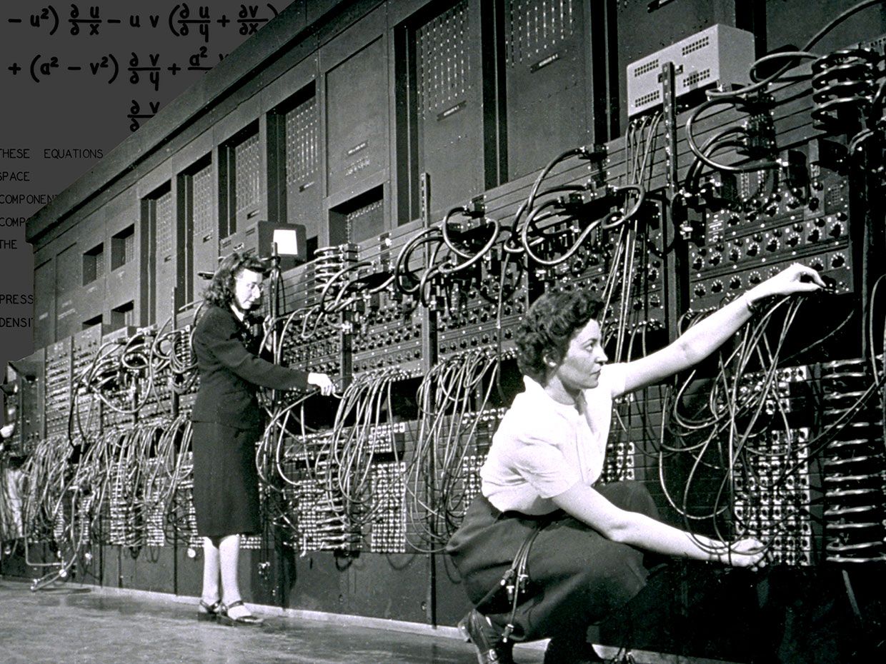
Marlyn Wescoff (left) and Ruth Lichterman program the ENIAC. (Corbis/Getty Images via IEEE)
The ENIAC was the fruit of an idea that had emerged 115 years earlier, when Charles Babbage, working with Ada, the Countess of Lovelace, developed a plan for an Analytical Engine. This was to be a machine which could not only perform fixed mathematical operations but also was “programmable”—it would be able to be modified on the fly to perform different functions, in different orders, as the ENIAC was. It’s difficult to overstate the importance of this leap from a fixed-use mathematical solving machine to one which can be programmed to produce different sorts of outcomes from the same input.
Lady Lovelace contributed enormously to the field with her insight that a computer “might act upon other things besides number,” which was the first known conceptualizing of the expansion of a computer’s power beyond the merely mathematically computational. With this, she allowed for an entirely different class of “arrows” to come into being; if non-numerical entities could be represented, and calculated, stored, etc., then the whole world may potentially be the arrow that any particular piece of a computer’s memory points towards.
Compilers
At the same time that the ability to program computers introduced a new era of possibility, it also brought with it enormous complexity. Remapping the logical operations of a computer was a very difficult and error-prone task; the computer programmer needed a precise and intimate understanding of that particular computer’s method of operation to be able to write successful instructions. Early computer instructions were written directly on punch tape in binary or by rearrangement of patch cables, processes which do not lend themselves to easy understanding or legibility. Generally, a program (or wiring arrangement) written to run on one model of computer would likely not run on a different one because of underlying differences in hardware.
In the nineteen fifties, people began to develop compilers: computer programs which could take instructions written in a fairly generic form and convert them into programs that would actually run on different pieces of computer hardware. The compilers read a piece of software and interpreted the author’s intent, capturing it in a set of formal instructions applicable to a specific type of hardware.
A compiler represents a sort of indirection (or arrow) which points from the programmer’s language to the “machine code” which will actually be executed by the computer. As “higher-level” computer languages were developed, the gap between the programmer’s original instructions and the underlying machine code grew. Instead of writing the fairly confusing MOVL $-0x8(%rpb), 0x4A, a programmer might now be able to write something more legible like x = 74; (in both cases, the purpose is to set a variable to have the value of 74).
There are more layers here, though. Going from a programmer’s instruction to an underlying behavior in the computer is not so simple as programmer–compiler–machine code; there are other intermediate steps involving further indirection, “linking,” and interpretation along the way. Once the instructions are in machine code, there is more interpretation done by the microcontroller, using yet another type of code called “microcode,” which provides further indirection/redirection when the code actually runs. Following is an example to briefly illustrate this process.
An example from the Arduino
If you wish to blink an LED on pin 13 of the Arduino, which is the typical point of entry to the hardware platform for new learners, you might run this bit of code:
void setup(){
 pinMode(13, OUTPUT);
}

void loop(){
 digitalWrite(13, HIGH);
 delay(1000);
 digitalWrite(13, LOW);
 delay(1000);
}
This is written in C. But what does the Arduino actually run? A generated hexadecimal file, which looks like this:
:100230000FB60F9211242F933F938F939F93AF93F9
:10024000BF938091010190910201A0910301B091AF
:1002500004013091000123E0230F2D3720F4019693
:10026000A11DB11D05C026E8230F0296A11DB11DD9
:10027000209300018093010190930201A093030158
These are lines 36 to 40 of the hexadecimal; it is 60 lines long. Here we have seen the two endpoints of the process, from highest-level (C) to lowest-level (hexadecimal machine code).
To see the indirection and reinterpretation in the midst of them we might examine something as simple as digitalWrite(), the command which turns a pin’s electrical output on or off. When the user asks the Arduino “integrated development environment” (IDE) to push their code to the board, it goes through many sequential steps, and one of them is locating and interpreting the definition of digitalWrite(), which is:
void digitalWrite(uint8_t pin, uint8_t val) {
 uint8_t timer = digitalPinToTimer(pin);
 uint8_t bit = digitalPinToBitMask(pin);
 uint8_t port = digitalPinToPort(pin);
 volatile uint8_t *out;
 if (port == NOT_A_PIN) return;

 // If the pin that support PWM output, we need to turn it off
 // before doing a digital write.
 if (timer != NOT_ON_TIMER) turnOffPWM(timer);

 out = portOutputRegister(port);
 uint8_t oldSREG = SREG;
 cli();
  if (val == LOW) {
   *out &= ~bit;
 } else {
   *out |= bit;
 }
 SREG = oldSREG;
}
This definition may be longer and more complex than we expect, but fundamentally the command is simply an on/off switch (lines 14 and 16 are the actual things that would prepare the Arduino to set a pin to turn on or off respectively). The definition itself rests on many other definitions; NOT_A_PIN, for instance, is just a variable, or symbol, storing the number 0. HIGH, similarly, is merely a variable pointing to the number 1. Ultimately every time any number is stored or referred to on a modern computer, the stored value is simply a series of tiny physical units which are either “high” or “low,” “on” or “off”—these may be transistors, regions of magnetic field or electrical charge, or a less-reflective vs. more-reflective area on a thin film of metal. Abstractions built upon abstractions built upon abstractions!
Getting back into our descent through the layers of abstraction: the first few lines of the Arduino’s assembler version of the digitalWrite() command look like this:
234: 56 ea       ldi r21, 0xA6 ; 166
236: e5 2e       mov r14, r21
238: 50 e0       ldi r21, 0x00 ; 0
23a: f5 2e       mov r15, r21
This is the penultimate level of proximity to the hardware; these assembly code instructions are (in a slightly simplified sense) turned into a part of the hexadecimal machine code shown earlier. Any microcontroller has a list of “opcodes,” i.e. operation codes, particular to it. These are often represented as three- or four-letter acronyms to help the human programmers who are using them, but in yet another indirection, the opcodes written in letters are themselves referring to a purely numerical value; for instance, LDI (“load immediate,” a basic process of writing a value to a memory location) is represented by opcode 1110. The ATMega328 has a list of about 100 such codes that will work on that hardware.
As you’ve seen in this section, even the relatively simple, inexpensive, and low-powered Arduino contains a real maze of layers of redirection. A laptop or desktop computer is a far more complex machine than those small chips, and with many more internal layers to show for it.
Emergent complexity
Computers are capable of undertaking truly complex tasks at high speed. Underlyingly the complexity they exhibit is a carefully choreographed interplay of many, many small, simple elements of information, called bits. Each little transistor, following a well-defined rule of electrical behavior, can be said to be a very small cog in a very large machine (for instance, the Atmel chip driving the Arduino Uno has perhaps a million or so).
In the natural world there are myriad examples of individual decision making elements working together in such a way that the complexity of the whole is significantly greater than the parts combined. Consider the flocking behavior of birds or fish: each animal can be modeled as following a simple set of rules regarding their own movement with respect to their peers, encoded by three parameters (cohesion, alignment, and separation). When the whole group follows such a set of rules, incredible larger-scale complexity emerges. Here is an interactive example of a population-level simulator of many individually driven elements; it’s an implementation of Craig Reynolds’s “Boids”:
Large-scale order can emerge from the “decisions” or behaviors of small individually mobile elements, even when there are seemingly no decision-making agents present; regular, periodic sand waves on a beach are merely the result of countless grains which have fallen into a large-scale order, a result of their individual and collective response to wind patterns. On a larger scale, given the right conditions, sand will form into slowly shifting dunes that are hundreds of feet tall.
We may contrive artificial systems which explore the results of many individually-acting elements sharing a common environment; the flock above is one example. A different sort of system can be modeled where each member of a two-dimensional grid has some awareness of the cells around it, and responds to them according to a set of rules; this was famously pioneered by John Conway, in his Game of Life, and Stephen Wolfram claims to have invented an entirely “new science” that’s driven by these “cellular automata.” In a rather stunning illustration of the higher-level complexity that can be achieved following these 2d grid-based systems, an internet denizen responded to an open challenge by constructing a functioning digital clock display built entirely in a Game of Life simulation.
It is tempting to relate the complex behavior of many small individual elements to our own brains, which are, after all, composed merely of many, many individual neurons, attached to each other in a complex web from which our consciousness arises.
Assignment
Working as a group, build a system, machine, installation and/or embodied creation that responds to, is inspired by, or is in dialogue with some of the ideas above. Your project must:
- Have at least one input stream from the larger environment
- Have at least one input stream from another group’s project
- Have at least one output stream (which another group’s project might read as an input)
You must consider some element of the larger context in your project’s design and/or content. For example, the architecture or environment your work will be installed in, physical characteristics of the space (light, sound, smell, etc.), the history of the building or components of CFA, the public that will be attending the event, or the performances or work from other courses.
Due dates
Mon, Nov 15: Initial Ideation Due
Prepare two distinct project ideas to turn in and discuss.
Each of your project ideas should include:
- A block diagram showing the flow of data through your system. This is an accounting of all inputs, computational steps, and outputs. We recommend you use Draw.io’s block diagramming mode to create this. You may also draw a figure by hand, or in other software of your choosing. Regardless of how you draw the figure, it should include:
- All of your system’s inputs on the left side of the drawing, connected by arrows to:
- Any/all of your system’s computational steps in the middle, connected by arrows to:
- All of your system’s outputs on the right.
- A narrative description (~250 word) addressing:
- Intended interaction mode by members of the public and/or performers and/or yourself (whatever is appropriate to the piece)
- Intended siting (where will it live and how will it be installed?)
- Intended experience for the audience
- Theoretical underpinnings (e.g. what led you to this idea, what about it intrigues you, etc.)
- A representative drawing of your proposed build (drawings need not be high-fidelity; sketches are certainly fine). Consider illustrating how your piece will live in context and not just what the objects will look like. This will help us understand scale and spatial concerns.
- Basic list of needed materials as well as sources (on or off campus) for those materials (this need not be a finalized purchase list!
We will review your proposals with you individually in class.
Wed, Nov 17: Group Check-in
Post your finalized idea to share with the class for feedback.
Mon, Nov 22: Proof of Concept Demo, Low-fi Maquette Presentation
You will present a proof of concept tech demo and low-fi maquette of your project to the class. It need not be high-fidelity. There is a lot of different thinking in the design world about what “prototyping” means. Designer and academic Graham Pullin, in his excellent Design Meets Disability (2011), helpfully outlines a few different approaches:
- looks-like prototype: an appearance model for form, color, materials, etc.
- works-like prototype: an engineering prototype for electronics and electromechanical build, etc.
- behaves-like prototype: an experience prototype for interactions. It may have tethers instead of being wireless, or be built larger than the proposed final size, but the fundamental user interactions are well-modeled. (p. 138)
For this assignment, you will be combining components of looks, works, and behaves-like prototype approaches. This piece must shows clear progress towards your final goal. Use this time to focus on the interactive and aesthetic aspects of the project.
Requirements:
- Requirements:
- A lo-fi maquette or meaningful start on the project with sketches that represent the physical embodiment/fabrication of the envisioned final project.
- A first pass at the electronics. Figure out your electronics needs and begin!
In class, we will discuss the prototypes. This deadline is meant to help you prepare to deliver a polished finished less than two weeks later.
Submit your maquette by adding it to your process blog documentation and sharing the URL of this post to Canvas via this assignment.
Thur, Dec 2–Fri Dec 3 Install in CFA, time TBA
Fri, Dec 3, 7pm Install Complete IDeATe End of Semester Event in CFA
Finals Week: Complete Critique & Documentation Due
Your presentations should address the following:
- Title
- Project Statement / Artist Statement
- Documentation of physically-built projects installed in CFA
- Challenges along the way, interesting findings, and/or lessons you’d like to share.
Documentation requirements
Each documentation submission must consist of at least:
- A “featured image” that is a good overall view of the project. This image should be one of the “well-shot” images described below, or a cropped subset of one of them.
- The project title.
- Careful and well-shot images of the final project.
Submit at least seven shots and these must include:
- Overall photo for proportion and scale
- Detail photo of any part that you’d like to highlight (up to 3)
- Gif or gifv or little .mov that shows the piece working (i.e. interacting with an input(s) and the output(s) that are derived.)
- Simple narrative description of the thing and usual operation of the thing—the type of plain and straightforward description that you might write in a letter to a child to explain what you had made. Free of judgment and totally literal and straightforward. Try to use as little technical language as possible. (E.g. “A white plastic box has a switch on the top side. When the user turns it on, a green LED flashes five times showing that the system is ready. A small white flag waves back and forth.”) For a study in the art of using simple language, see Randall Munroe’s wonderful Up Goer Five. To use a simple-language filter yourself, try the Up-Goer Five text editor.
- Five progress images, each of which could be a step or misstep that happened along the development process, and each with at least a sentence or two caption. These images may capture decision points, especially interesting or illustrative mistakes, or other mileposts along the way. The idea is that these medium-quality images (though good pictures work too) are taken along the way to document progress. Sometimes you might understand these as being moments-that-matter only in retrospect! The safe route, therefore, is to snap lots of photos as you go along for later review.
- Process Reflection pertaining to process and outcome. For instance, what was easy, what was hard, what did you learn? What little tweak, in retrospect, would’ve changed the direction entirely? This is an opportunity for you to reflect on your creative and technical growth through the project, and think about what growth you want to aim for next. This shouldn’t be a recital of your process, but rather a meaningful consideration of what you experienced during the creation of your piece, 2–4 paragraphs in length.
- Code submission (if using Arduino), embedded into the project page, and optionally also with a Github or other version control service public-facing link. Your code should be reasonably commented throughout so that people other than you (the author) can better understand it. You don’t need to explain every single line—that would be overkill—but leave useful notes in a reasonable measure. Write a comment block at the top of the code including:
- the project title,
- (optionally) your name,
- a description (short or long) of what the code does,
- any description of pin mapping that would be useful to somebody else trying to recreate your work,
- appropriate credit to any other person’s/project’s code that you incorporated into your project, and
- (optionally) a license notice (i.e. copyright, CC BY-SA 4.0, the MIT License, release it to the public domain, or just follow your heart). If you have written code that you wish to keep strictly proprietary for any reason, please speak with the instructor about an exception to this documentation requirement.