Exercise: Read Analog Accelerometer
Objective
Measure motion and tilt as numbers. Use the serial port for debugging.
The world is an analog place; physical phenomena have continuity and exist over time. To represent a physical property computationally, the physical process information must be transduced into electrical form and then converted from an analog voltage into a digital number by an analog-to-digital converter, or ADC.
This is a wide and deep topic ranging from signal and information theory to robotics and epistemology, and we will only just begin to explore this idea. But to start, this exercise will represent a physical pose and trajectory as several streams of integers.
An accelerometer is essentially a tiny mass suspended on three tiny springs at right angles. Each output is the measured deflection of one of the springs When at rest, gravity pulls the mass down and the three outputs reflect the direction of the gravity vector. When in motion, the acceleration of the chip pulls on the mass through the springs, and the output reflects the combination of the gravity vector and the acceleration vector. When falling, all springs can relax and the output is the zero vector.
Steps and observations
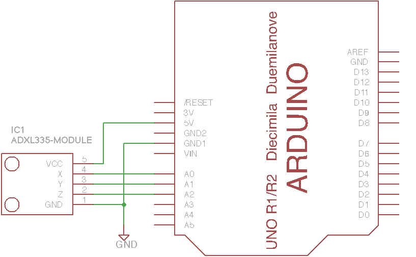
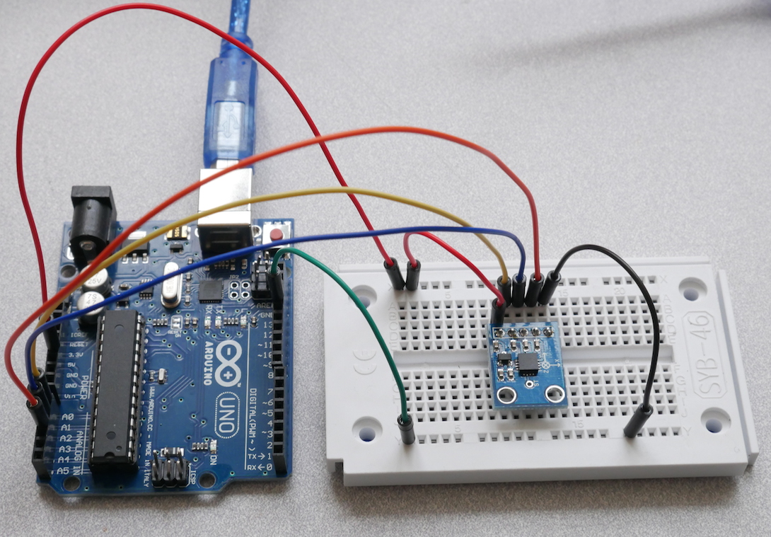
Wire the circuit on the breadboard. Note that this module has amplified voltage outputs which can drive the analog pins directly. (It is not a resistive sensor like the photocell.)
Load and run the ReadAccelerometer sketch.
Within the Arduino IDE, open the serial monitor console and make sure it is set to 9600 baud.
Observe the numbers printed in the serial monitor as you tilt the sensor slowly.
Try slowing the sampling rate by increasing the delay.
Determine the highest and lowest values observed.
Observe the noise in the numbers for different constant inputs.
The numbers produced by the ADC are a voltage measurement expressed in the somewhat arbitrary units of the converter (e.g. 4.9 mV/unit).
The arithmetic for the calibration mapping can be as simple as multiplying by a constant gain and adding an offset (e.g. a linear function); the key point is choosing a units system which is understandable and deciding how to take repeatable reference measurements.
A sample calibration is in the code; formulate a strategy for calibrating the measurement so that the numbers are more precise.
Try jerking the sensor along one axis without tilting it; can you see the transient signal in the corresponding axis?
Comments
The Arduino analog inputs are converted at 10 bits of precision, that is, voltages between 0 and 5V are measured as integer numbers between 0 and 1023, with a nominal resolution of about 4.9 mV per step. However, analog noise in the conversion also limits the precision, so the minimum detectable signal change may be somewhat larger.
The frequency resolution is determined by the sampling rate and the Nyquist-Shannon sampling theorem, which states that a periodic sampling rate must be at least twice as fast as the highest frequency in the input. The Arduino ADC converter runs at a maximum of about 10 kHz, so in principle it can measure signals which vary at up to a 5 kHz rate.
Arduino Code
- Documentation: ReadAccelerometer Arduino Sketch
- Sketch Folder: ReadAccelerometer
Suggested Layout
Other Files
- EAGLE file:
read-analog-accel.sch