Exercise: Photocell with bias resistor
Objective
Measure changing light level as a varying voltage.
A CdS photocell (i.e. Cadmium-Sulfide photoresistor) is a light sensor in which the resistance changes in response to illumination. They are relatively slow, with a time constant of hundreds of milliseconds, but useful for measuring ambient light and shadow. The resistance decreases in bright light; a typical range might be from 50K in darkness down to a few hundred ohms near a lamp.
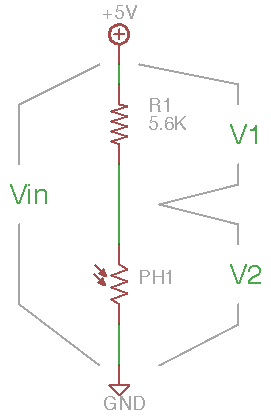
A voltage divider circuit can be used for creating a voltage which depends on the light level. The value of the fixed resistor depends upon the desired sensitivity range; a good starting point to try is roughly equal to the photocell resistance at mid-range.
Steps and observations
- Measure the resistance of the photocell over different illumination conditions.
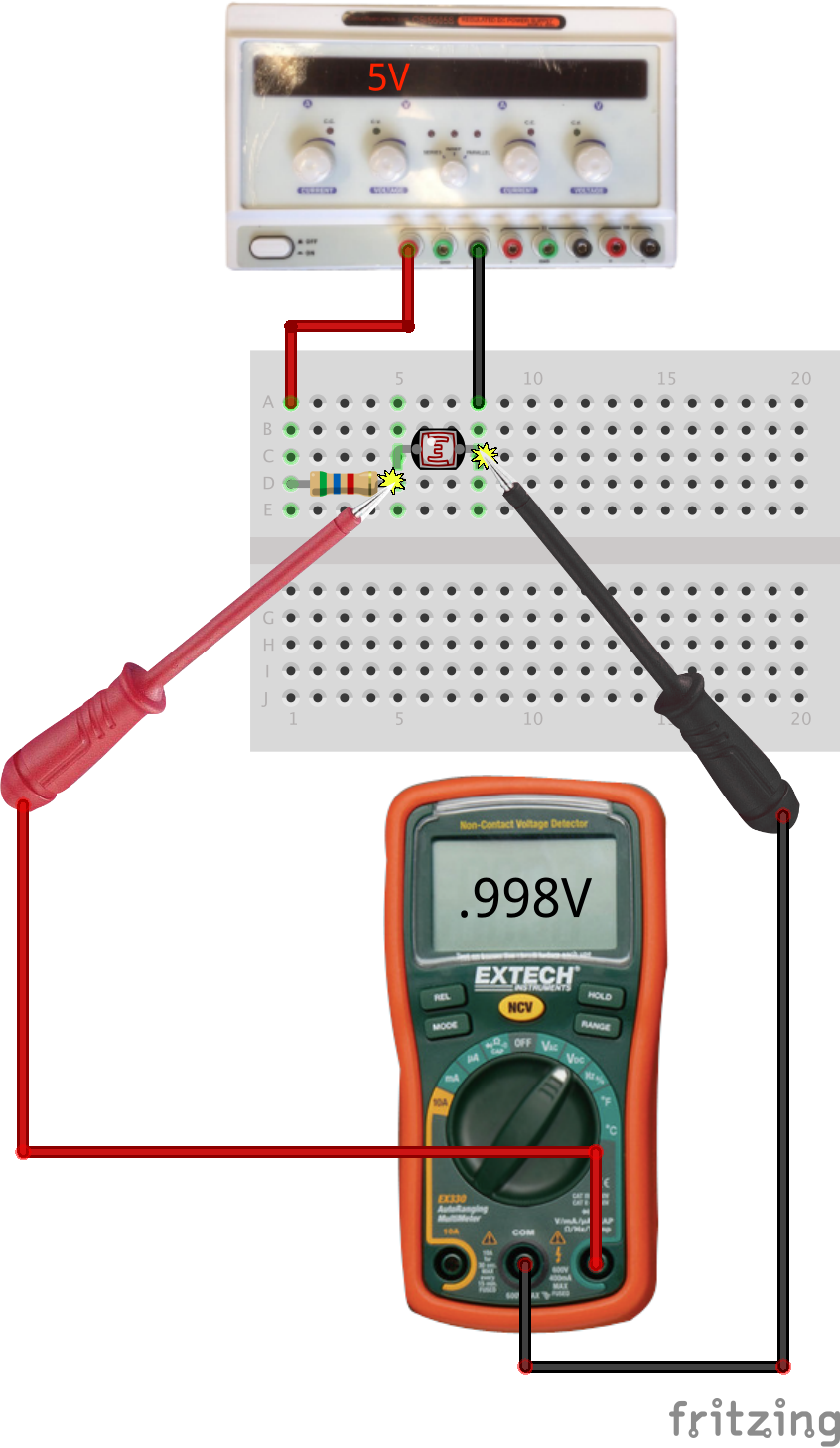
- Measure the photocell voltage in the given circuit over different illumination conditions.
- Using the oscilloscope to observe the photocell voltage, try creating rapidly changing shadows to estimate the response speed.
- Construct a simple setup to indirectly measure a physical property using a photocell. This can be as simple as using paper to occlude the light sensor as a function of mechanical position. (Keep this simple, this should only take a minute or two.)
Comments
Rapid light changes and optically encoded data are better measured with phototransistors and photodiodes. But even slow and cheap light sensors can be adapted to measure many other properties indirectly, e.g. chemicals, dust, mechanical position, acceleration, proximity, etc.
The circuit is drawn with a pull-up resistor. What happens when the roles of R1 and the photoresistor are swapped?
For a challenge, find one of the laser diodes and measure the photocell response to the laser beam.
Other Files
- Fritzing file:
photocell-with-bias-resistor.fzz - EAGLE file:
photocell-with-bias-resistor.sch