Exercise: Resistor Voltage Divider
Objective
Measure voltages and compute current flow in a voltage divider formed by two fixed resistors. Practice using a breadboard and DMM.
Many sensor circuits we use will be built around an arrangement of series resistances called a voltage divider. This is a fundamental construction which will appear again and again.
Two resistors in series form a single current pathway, so a voltage \(V_{in}\) applied across the pair will cause the same current \(i\) to flow through each of them. However, the voltage drop across each resistor resulting from that current is proportional to the resistance (\(V_1 = i * R1\), \(V_2 = i * R2\)), so the voltage at the intermediate node depends on the relative resistances. In the simplest case, if both resistances are the same, the voltage in the middle will be the average of the voltage at each end.
We will use the voltage divider structure to allow a variable resistance (e.g. sensor or switch) to control the voltage at the intermediate point. This is useful for us because the analog-to-digital converter on the Arduino senses applied voltage.
Steps and observations
- Choose two resistors of nominally equal value. Any value between 100 and 4700 ohms is fine.
- Measure the exact resistance of each resistor.
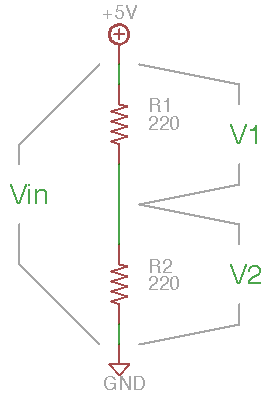
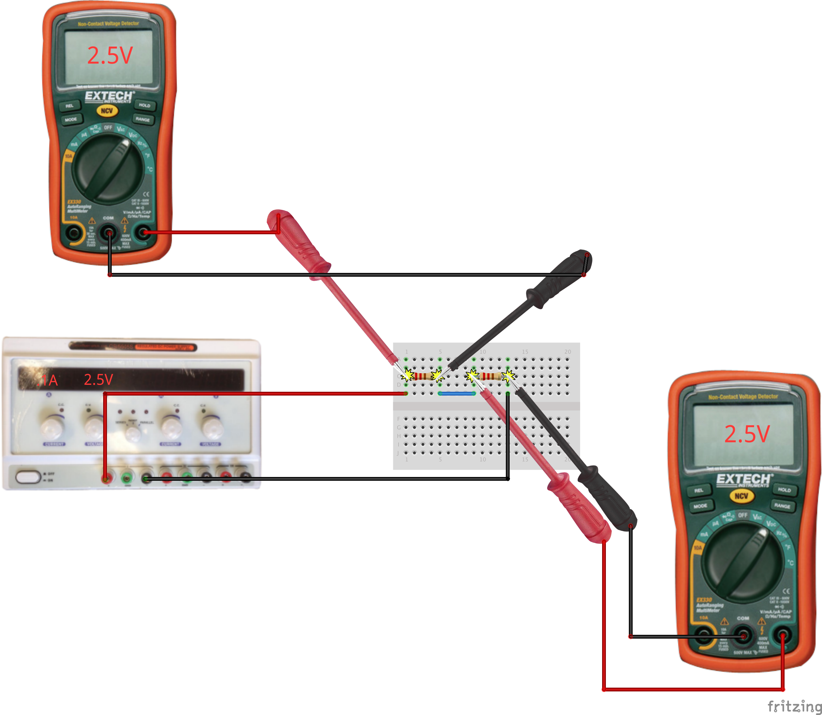
- Set up the divider on a breadboard; a suggested layout is shown below.
- Carefully measure the voltage \(V_{in}\) applied across the series pair of resistors. This should be your supply voltage (\(V_{in} = V_1 + V_2\)).
- Compute the expected voltage \(V_2\) across the grounded resistor: \(V_2 = V_{in} * (R_2 / (R_1+R_2))\) where \(R_1\) is the ‘upper’ resistor connected to the positive supply and \(R_2\) is the ‘lower’ resistor connected to ground.
- Vary the input voltage and repeat; you should be able to convince yourself that the intermediate voltage scales proportionately.
- Open the circuit and measure the actual current through the divider. Compare against the predicted value: \(i = V_{in} / (R_1 + R_2)\).
Other Files
- Fritzing file:
voltage-divider.fzz - EAGLE file:
voltage-divider.sch