Course Kit Guide
The course includes a kit of electronic parts which will enable a wide array of small projects. Students are responsible for their own mechanical or structural materials, project housings, or decorative elements. The following is a quick visual guide to everything provided in the kit. For reference, the total cost is about $25 per kit in bulk.
Core Components
Arduino

The Arduino is the tiny computer (microcontroller) we will programming in this course. It also comes with a blue USB cable (not shown) to plug into a laptop in order to program it. We will also power it from the laptop, although it can run independently if provided a suitable power source.
Solderless Breadboard
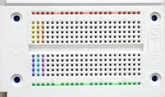
The solderless breadboard provides a workspace for building circuits. Jumper wires and many components can be inserted directly into the holes. The kit includes one short breadboard.
The color highlights show some of the connected circuit points: each long row is internally tied together, as are each of the short rows. Building a breadboard circuit requires translating the logical connections of a schematic into a physical layout in which all component pins constituting a single electrical node are electrically connected, either via the internal breadboard connections or jumper wires.
Jumper Wires
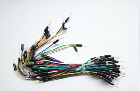
The jumper wire kit is used to build circuits. The pins can plug either into the Arduino connectors or the breadboard circuit points.
Plastic Box
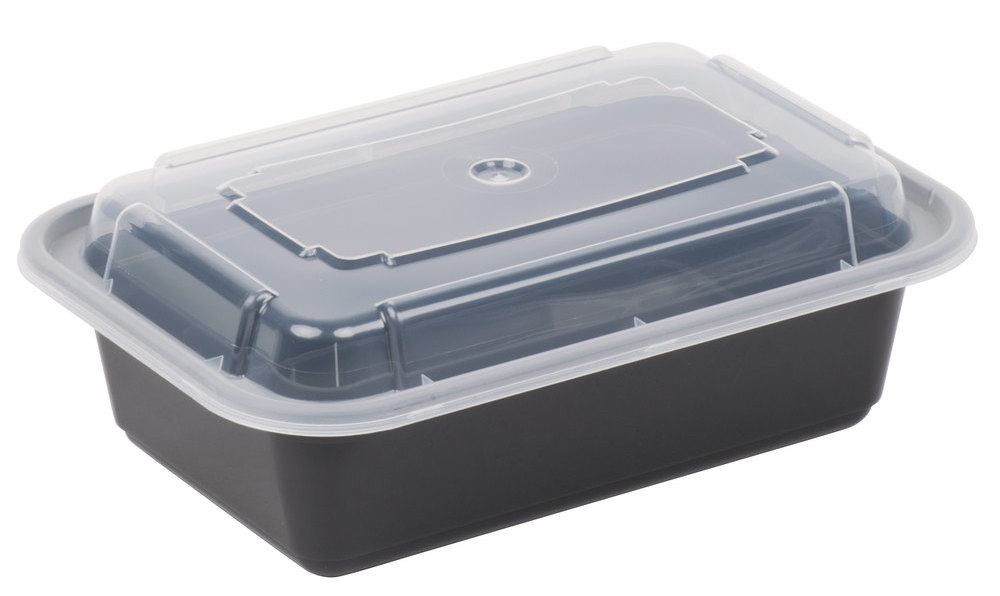
It’s a 24 oz takeout container to hold everything else, but could also be used as a housing for a project.
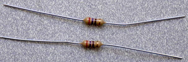
5.6K Resistors
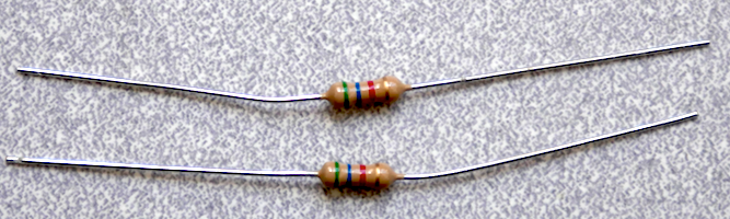
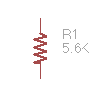
These are 5.6K (5600 Ohm) resistors we will use as ‘pull-up’ resistors for switches and photosensors. The green-blue-red-gold color bands indicate the value using the standard resistor code code. Green-blue indicates ‘56’, and red adds two zeros for ‘5600’ ohms. The gold band indicates a +/- 5% tolerance on this value. These are carbon-composition resistors rated at 1/4 Watt dissipation.
270 Ohm Resistors

These are 270 Ohm resistors we will use as ‘dropping’ resistors for LEDs. The red-violet-brown-gold color bands indicate the value using the standard resistor code code. Red-violet indicates ‘27’, and brown adds one zero for ‘270’ ohms. The gold band indicates a +/- 5% tolerance on this value. These are carbon-composition resistors rated at 1/4 Watt dissipation.
Sensing (Input)
Switches

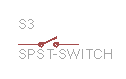
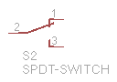
Several small switches are provided. This usually need to be connected in a simple circuit with a resistor to produce a change in electrical voltage or current from a mechanical input.
Photoresistor
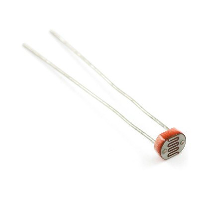

The photoresistor is a simple optical transducer which changes resistance in response to overall light level.
HC-SR04 Ultrasonic Ranger
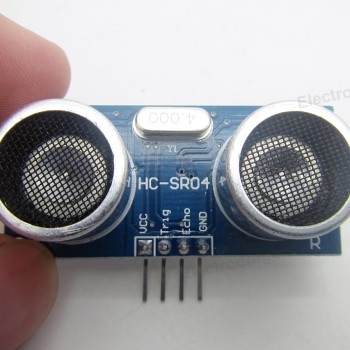
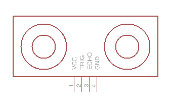
The ultrasonic ranger is a single-channel sonar which emits short pulses of ultrasonic sound and times the interval until an echo is detected. They can be used for detecting proximity and measuring distance.
Accelerometer Module

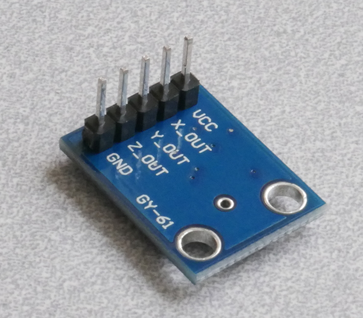
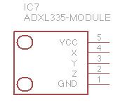
The 3-axis ADXL335 accelerometer is an inertial sensor which measures either tilt or acceleration. This module also includes a voltage regulator to reduce a 3-5V supply to a safe supply voltage for the sensor.
The sensor chip on the module is an ADXL335: home page, datasheet.
Note: the pins are included unassembled in the package and must be soldered to the board.
Actuation (Output)
LEDs
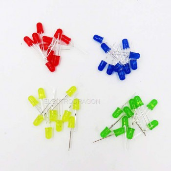

Several LEDs are provided. This must be used with an appropriate resistor to limit the total current.
Micro Servo
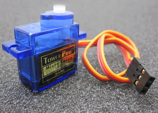
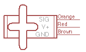
The micro servo is a motor with position control. The Arduino can generate a particular control signal indicating the angular position to which the servo should rotate. Internally it has a gearmotor, position sensor, and feedback circuit to reach and hold a target angle.
Transistor Driver Integrated Circuit
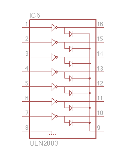
The ULN2003 is an integrated circuit with seven output channels capable of driving a motor, speaker or solenoid at higher power levels than the Arduino can itself provide.
Speaker


The speaker (half-watt, 8-ohm) can be driven with the ULN2003 to make tones. Wires will need to be soldered to the pads in order to connect to the breadboard.
Pager Motor

The pager motor is a tiny 3V DC motor with an off-center mass which produces a perceptible vibration. It is recommended that you solder wires to the short pins in order to connect to a breadboard.