Reading a photoresistor: how light is it?
A photoresistor is a device whose electrical resistance changes based on the amount of light hitting it.
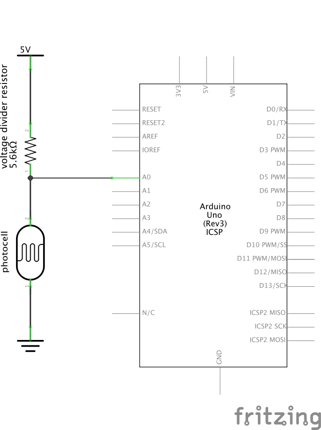
A standard photocell is very easy to wire up, as shown in the schematic.
The purpose of the 5.6kΩ resistor in series with the photocell is to make it so that the photocell’s changing resistance is reliably detectable.
You might be tempted to attach 5V to one side of the photocell, and the other side to A0. But! Consider that at very high photocell resistances this is like leaving A0 with a floating input (which would give you unpredictable values); and at any lower values, it’s just wiring 5V right into A0 (which should just read as 5V all the time). That’s why instead of doing that you build a “voltage divider” circuit like the one shown here in schematic form:

The voltage divider
To understand how the voltage divider works, let’s follow the electricity. It starts at 5V, and is forced to go through the 5.6KΩ resistor. Then it reaches a node, or place where more than two things are connected; it is at this node that the Arduino measures the voltage.
Imagine the case where the photocell has very high resistance, like 200KΩ: in that case, the electrons at the node in the circuit look to one side and see a 5.6KΩ resistor, and beyond that 5 volts. They look to the other side and see a very high resistance, so much so that it nearly doens’t matter what’s on the far side of that huge resistor. The electrons hear “5V” being shouted quite loud, and the faintest whisper of “ground.” The 5 volt potential wins, and the Arduino’s analog read port will see very nearly 5 volts. (In analogRead terms, this is 1,023.)
Imagine the opposite case, where the photocell has a very low resistance, say 10Ω. In this case, looking through the photoresistor, the electrons in the middle see a small resistor and then 0V (ground) beyond that. On the other hand, looking through the relatively very large 5.6KΩ resistor, with the 5V past it, they can barely see the far side. These electrons are hearing “ground” shouted and a little meek voice saying “5V,” and ground wins. The Arduino will read a value close to 0. (In analogRead terms, this is 0.)
Finally, imagine the case where the photocell has a resistance of 5.6KΩ. The electrons look to the right and see 5V, look to the left and see 0V, and they’re both equally hard to get to. They are equally affected by both voltages, and therefore the electrons in the middle will actually equilibrate to the average of the two voltages on either side: 2.5V in this case. (In analogRead terms, this is 512.)
Arduino code to read an analog value and print via the serial monitor
1 2 3 4 5 6 7 8 9 10 11 12 13 | int photocell = A0; // shortcut to refer to the photocell pin later
void setup() {
pinMode(photocell, INPUT); // we will be reading the photocell pin
Serial.begin(9600); // starts serial communication at 9,600 baud (the rate)
}
void loop() {
int readVal; // initialize a new integer to store the photocell value
readVal = analogRead(photocell); // do the analog read and store the value
Serial.println(readVal); // push the most recent value to the computer
delay(50); // slow the loop down a bit before it repeats
}
|
Download link for the above code: analogReadSerial.ino.