Course Kit Guide
The course includes a kit of electronic parts which will enable a wide array of small projects. Students are responsible for their own mechanical or structural materials, project housings, or decorative elements. The following is a quick visual guide to everything provided in the kit. For reference, the total cost is about $35 per kit in bulk.
Inventory
| description | kit quantity | approximate price each |
|---|---|---|
| Arduino-Compatible Uno R3 EDArduino incl. USB cable | 1 | $11 |
| 9G Micro-Servo (For RC Helicopter Boat Plane Car) | 1 | $1.70 |
| IRF540 MOSFET | 1 | $1.20 |
| Solderless Breadboard, Long | 1 | $4 |
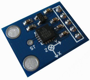
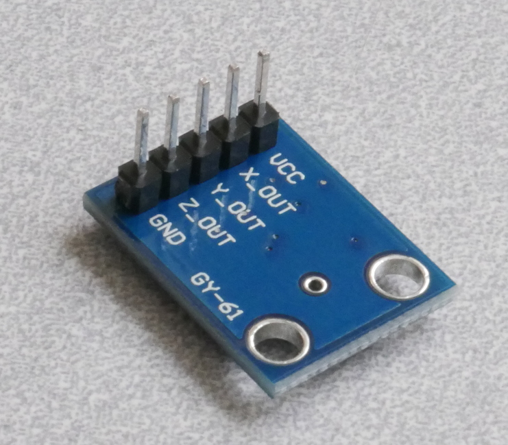
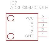
| ADXL345 Triple-Axis Accelerometer Module | 1 | $4 |
| General Wire Kit (Approx 65pcs) | 1 | $1.50 |
| assorted 5mm colored LEDs | 10 | $0.02 |
| HC-SR04 Ultrasonic Proximity Sensor | 1 | $1.50 |
| Photointerrupter, through-beam, V69 605 TCST 1103 | 1 | $0.82 |
| Photointerrupter, reflective, NPN Phototransistor, LTH 1550-01 | 1 | $0.29 |
| 7805 voltage regulator, TO-220 | 1 | $1 |
| 1N4004 diode | 1 | $0.05 |
| ULN2003A Darlington Driver, Transceiver, DIP16 | 1 | $0.43 |
| DIP pushbutton momentary switches | 2 | $0.02 |
| SPST lever microswitch | 2 | $0.86 |
| SPDT slide switch | 2 | $1 |
| 10K board-mount potentiometers | 2 | $0.56 |
| pager motor | 1 | $1.95 |
| 5mm Mini Photocell, CdS photoresistor | 2 | $0.06 |
| resistor, 1/4W, 10K | 5 | $0.01 |
| resistor, 1/4W, 330 ohm | 5 | $0.01 |
| resistor, 1/4W, 5.6K | 2 | $0.01 |
| 28oz takeout container with lid | 1 | $0.70 |
Core Components
Arduino Uno
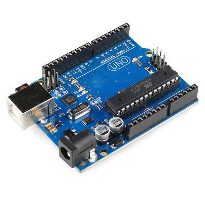
The Arduino is the tiny computer (microcontroller) we will programming in this course. It also comes with a short blue A to B USB cable to plug into a laptop in order to program it. It’s easiest to power through the USB cable, but it can also get power from another source that provides 7–20V DC.
Solderless Breadboard
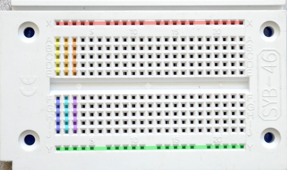
A solderless breadboard is a huge time-saver that lets you connect things electronically. The ancestor of the solderless breadboard was the regular, solder-using breadboard; one version of this is a board with big globs of solder that the user would melt, smush the legs of some different electronic components into, and then allow to cool. You’re lucky not to have to use those.
The internal connections of the solderless breadboard are hidden and they follow a convention that can be surprising at first:
In any row, a,b,c,d,e are connected to each other.
Likewise, in any row, f,g,h,i,j are connected.
- Along each edge there’s a long blue and red stripe:
- The whole red column is connected.
- The whole blue column is connected.
Jumper Wires
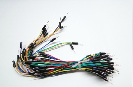
The jumper wire kit is used to build circuits. The wires can plug either into the Arduino connectors or the breadboard circuit points.
The kit we provide has wires with “pins” at both ends, and therefore these are called “male-male” wires. Wires can also terminate in a receptacle, which is called a “female” end, so a wire with receptacles at both ends is a “female-female” wire. The third type, of course, is the “male-female” wire, which acts like an extension cord.
Plastic Box
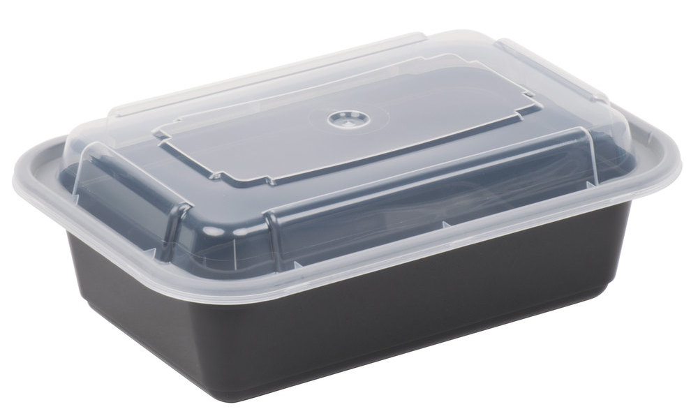
This is a 28 oz takeout container to hold your course kit, but could also be used as a housing for a project.
10K Resistors
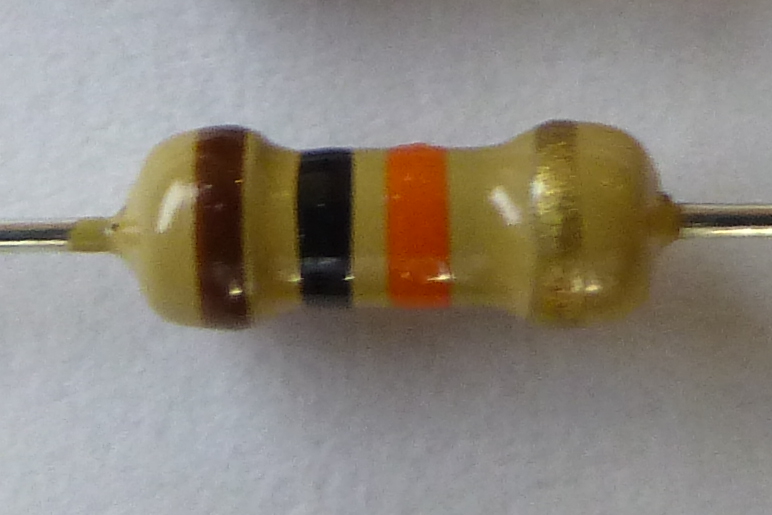
These are 10K (10,000 Ohm) resistors we will use as ‘pull-up’ or ‘pull-down’ resistors for switches other sensors. The black-brown-orange-gold color bands indicate the value using the standard resistor code code. Black-brown indicates ‘10’, and orange adds three zeros for ‘10,000’ ohms.
The gold band indicates a +/- 5% manufacturing tolerance around the nominal value, meaning the highest value this one should be is 10,000 Ohms x 1.05 = 10,500 Ohms, and the lowest it should be is 10,000 Ohms x 0.95 = 9,500 Ohms. (If you spend more money, you can get resistors with tighter tolerances but for general applications it’s not necessary.)
The kit resistors are rated at 1/4 Watt dissipation. If you push more than 0.25 Watts of power through them, they are at risk of overheating, which smells bad because it is bad.
5.6K Resistors
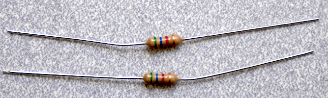
These are 5.6K (5,600 Ohm) resistors we will use as ‘pull-up’ resistors for switches and photosensors. The green-blue-red-gold color bands indicate the value using the standard resistor code code. Green-blue indicates ‘56’, and red adds two zeros for ‘5,600’ ohms.
The gold band indicates a +/- 5% manufacturing tolerance around the nominal value, meaning the highest value this one should be is 5,600 Ohms x 1.05 = 5,880 Ohms, and the lowest it should be is 5,600 Ohms x 0.95 = 5,320 Ohms. (If you spend more money, you can get resistors with tighter tolerances but for general applications it’s not necessary.)
The kit resistors are rated at 1/4 Watt dissipation. If you push more than 0.25 Watts of power through them, they are at risk of overheating, which smells bad because it is bad.
330 Ohm Resistors
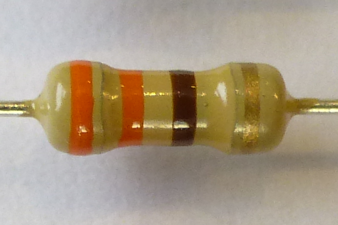
These are 330 Ohm resistors we will use as ‘dropping’ resistors for LEDs. The orange-orange-brown-gold color bands indicate the value using the standard resistor code code. Orange indicates ‘3’, or orange-orange means ‘33.’ Brown adds one zero for ‘330’ ohms. The gold band indicates a +/- 5% tolerance on this value. These are carbon-composition resistors rated at 1/4 Watt dissipation.
Sensing (Input)
Switches
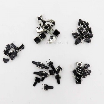
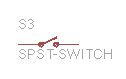
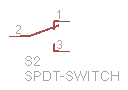
A handful of different switches are in the kit. Some of them are “momentary,” which means they will only be switched into a different mode while something is pushing/pulling on it, and others are “maintained,” in that they will maintain whatever position they were last pushed/pulled into. A regular light switch is “maintained,” and a car horn is “momentary.” (Ideally.)
Photoresistor
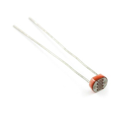

The photoresistor is an optical transducer which changes its resistance in response to overall light level. These are quite sensitive devices and so can do things like see very slight shadows being cast.
HC-SR04 Ultrasonic Ranger
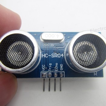
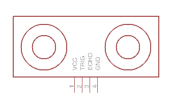
These ultrasonic rangers are a small and surprisingly inexpensive sonar which emit short pulses of ultrasonic sound from a transmitter and times the interval until an echo comes back to the receiver. They work best in the range ~10cm to ~200cm (~6” to ~6’).
Actuation (Output)
LEDs
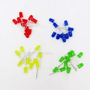

LEDs are “light emitting diodes.” They are diodes (i.e. they only allow electrical current to flow through them in one direction) which emit light as electricity is going through. If you don’t want to destroy your LED, you’ll want to limit the amount of current that can pass through it using a “ballast resistor” (330Ω is a reasonable value).
Micro Servo
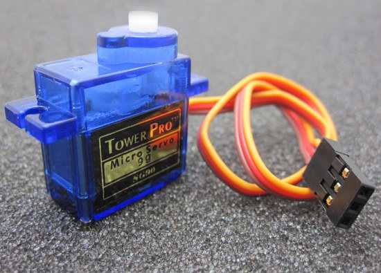

The micro servo is a motor that has awareness of its position. The Arduino can generate a digital control signal instructing the servo’s electronics where it should turn its motor to. The servo has a very small DC motor inside, a gear train to slow it down and give it more torque, a position sensor so the device knows where its motor is pointing, and some control electronics which receive signals from the Arduino and move the motor to the right position.
Transistor Driver Integrated Circuit
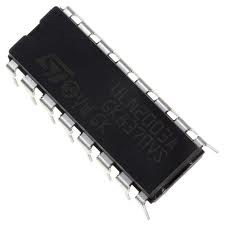
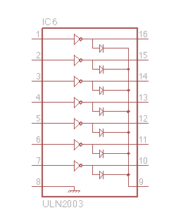
The ULN2003 is an integrated circuit with seven output channels capable of driving a motor, speaker, solenoid, or other device at higher power levels than the Arduino can itself provide.