Group Members: Becca Epstein, Becca Wolfinger, Zade Delgros
Roles: Becca Epstein as Tutor, Becca Wolfinger as Scribe/Integrator, Zade Delgros as Designer
Introduction
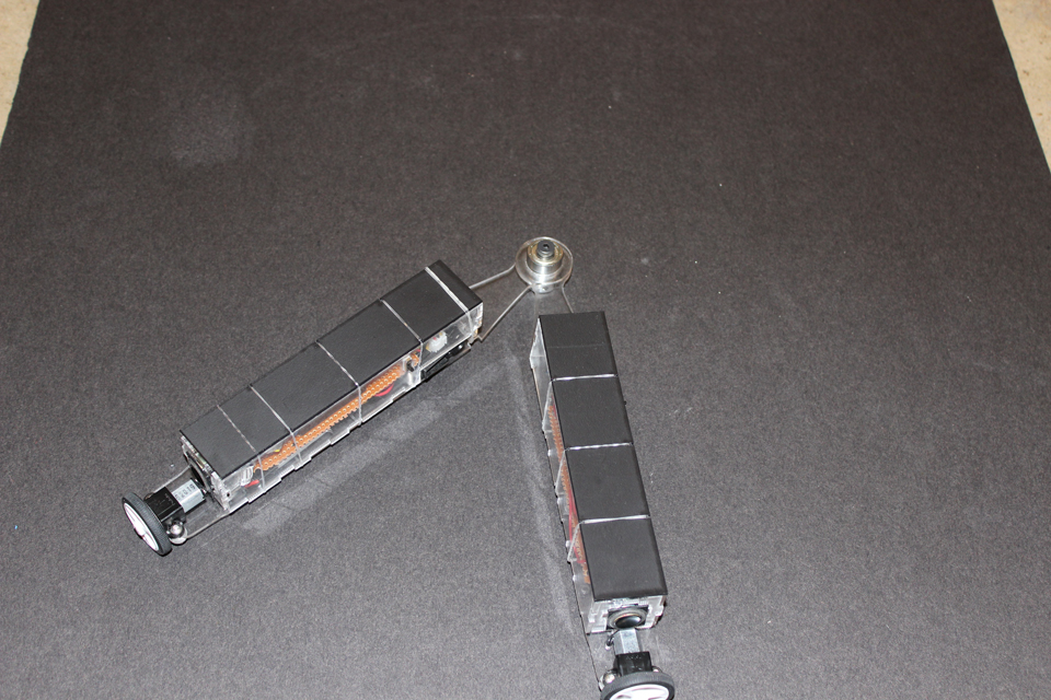
For this iteration, we were focused on getting more interesting behavior out of our autonomous robots “Ella and Chase”. To achieve this, we thought hard about what kind of personalities we wanted to embed in these robots. Our thought was to give each robot its own culture. Our goal in this piece was to illustrate the innate similarity between people as human beings despite the different ways we all perceive the world. To display these perceptual differences, we gave each arm a difference sensing mechanism. One arm looked out into its environment to control its direction. We made the other arm much more introspective by programming it to use its own acceleration and timing mechanisms in order to make decisions about its speed, direction, and the sounds it made.
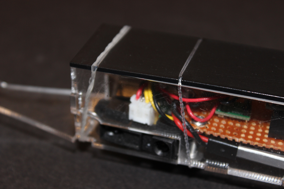
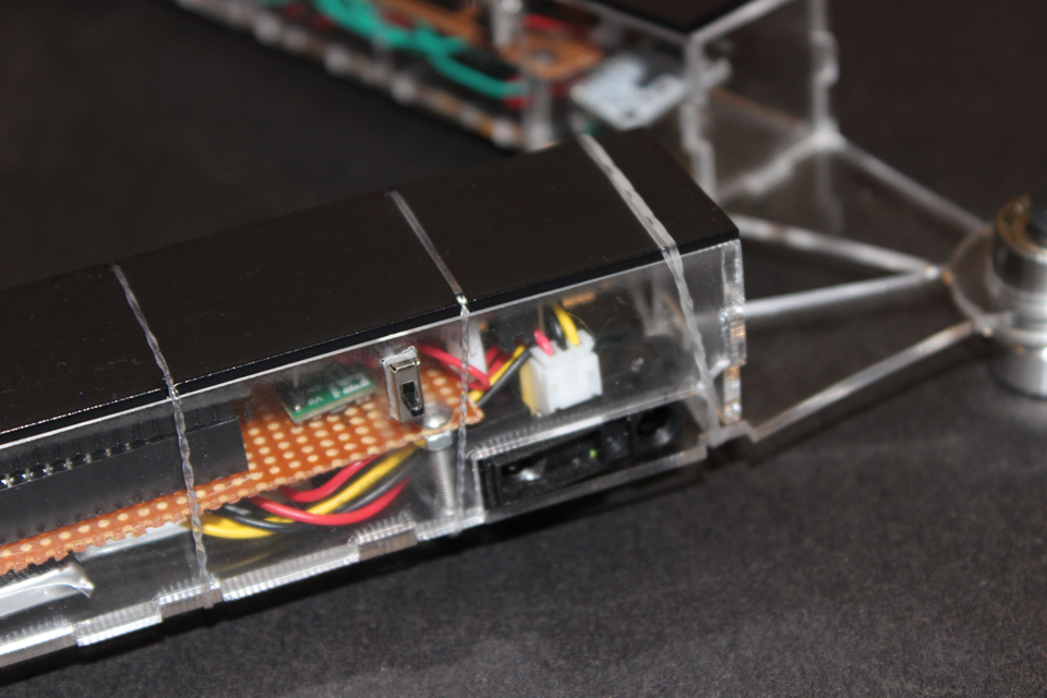
In addition to the illustration of this concept, we also rethought the design of the cars. We wanted to make the circuity cleaner and more compact. This proved to be quite difficult because we added several components and planned to pack them all into a much smaller space. We used the clear acrylic to expose the hardware of the robots and highlight that innate metaphorical similarity between people despite differences in culture or perception.
Video
Technical Notes
Arm 1:
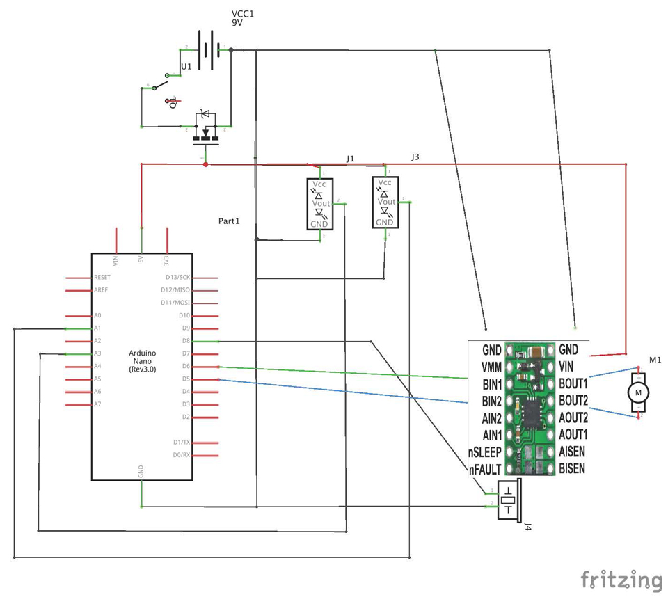
Our circuit consisted of an arduino nano, a drv883 h-bridge, a motor, 2 proximity sensors, a 5V step-up, a switch, a speaker, and a 3.3-volt Lipo battery. The switch and battery powered the entirety of the circuit, and the step-up stepped the battery up to a useable 5-volts. The proximity sensors were connected to analog pins 1 and 3 to send the arduino specific distances. The arduino was connected by pins 5 and 6 to the h-bridge to send logic to the motor to have it switch directions when the proximity sensor gave values after a specific threshold that would allow it to switch states from forwards to backwards. The speaker was connected to pin 8 to change the pitch.
Arm 2:
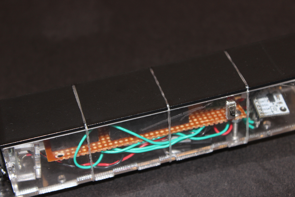
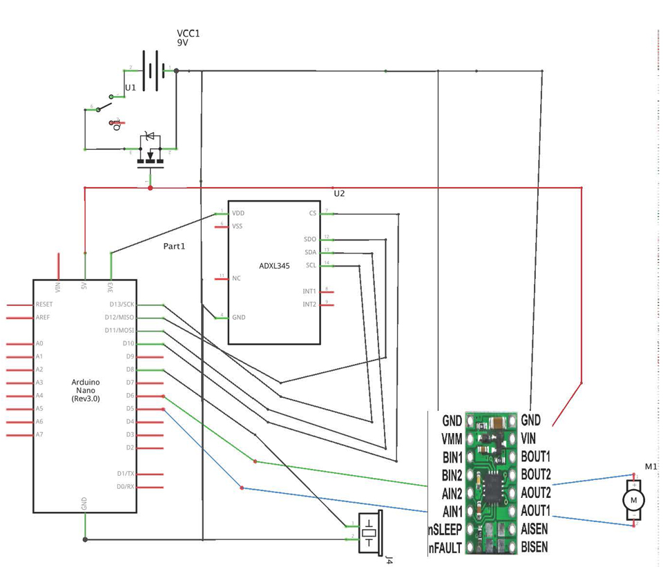
Our circuit consisted of an arduino nano, a drv883 h-bridge, a motor, a ADXL345 accelerometer, 5V step-up, a switch, a speaker, and 2 3.3-vold Lipo battery. The switch and battery powered the entirety of the arduino circuit, and the step-up stepped the battery up to a useable 5-volts while the other Lipo battery powered the H-bridge. The accelerometer was connected to digital pins 10-13 to send the arduino specific velocities. The arduino was connected by pins 5 and 6 to the h-bridge to send logic to the motor to have it switch directions , and by pin 8 to the speaker to change pitch, when the acceleromoter gave values after a specific threshold.
Photos
Autonomous robot overall view
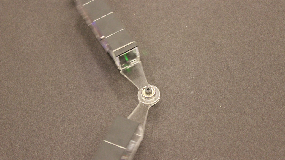
Robot in motion
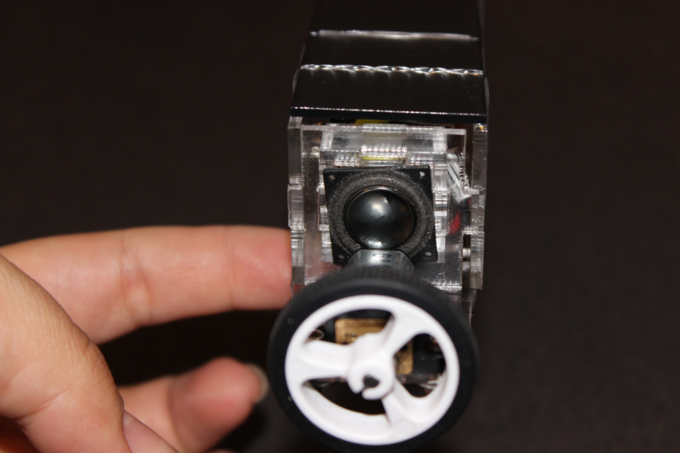
Robot with close up of moving part
proximity sensor left side
proximity sensor right side
Acceleration sensor
schematic for extroverted device
schematic for introverteddevice
Code
Introverted
//from https://www.sparkfun.com/tutorials/240
/*
* Introverted Arm
*/
//Add the SPI library so we can communicate with the ADXL345 sensor
#include
#include
#define MOTOR1A 5
#define MOTOR1B 6
//Assign the Chip Select signal to pin 10.
int CS=10;
//This is a list of some of the registers available on the ADXL345.
//To learn more about these and the rest of the registers on the ADXL345, read the datasheet!
char POWER_CTL = 0x2D; //Power Control Register
char DATA_FORMAT = 0x31;
char DATAX0 = 0x32; //X-Axis Data 0
char DATAX1 = 0x33; //X-Axis Data 1
char DATAY0 = 0x34; //Y-Axis Data 0
char DATAY1 = 0x35; //Y-Axis Data 1
char DATAZ0 = 0x36; //Z-Axis Data 0
char DATAZ1 = 0x37; //Z-Axis Data 1
//This buffer will hold values read from the ADXL345 registers.
char values[10];
//These variables will be used to hold the x,y and z axis accelerometer values.
int x,y,z;
int initx,inity,initz;
const int numReadings = 20; //length of smoothing array
int minPitch = 220;
int maxPitch = 1400;
int readings[numReadings]; //create array for smoothing
int index = 0;
int total = 0;
int average = 0;
int pitch = 220;
int stay = 10;
int checkCount= random(50, 100); //Randomize acceleration threshold for interesting behavior
int avgDist = 0;
boolean forward = true;
void setup(){
//Initiate an SPI communication instance.
SPI.begin();
//Configure the SPI connection for the ADXL345.
SPI.setDataMode(SPI_MODE3);
//Create a serial connection to display the data on the terminal.
Serial.begin(9600);
pinMode(MOTOR1A, OUTPUT);
pinMode(MOTOR1B, OUTPUT);
//Set up the Chip Select pin to be an output from the Arduino.
pinMode(CS, OUTPUT);
//Before communication starts, the Chip Select pin needs to be set high.
digitalWrite(CS, HIGH);
//Put the ADXL345 into +/- 4G range by writing the value 0x01 to the DATA_FORMAT register.
writeRegister(DATA_FORMAT, 0x01);
//Put the ADXL345 into Measurement Mode by writing 0x08 to the POWER_CTL register.
writeRegister(POWER_CTL, 0x08); //Measurement mode
//base readings for difference
//Reading 6 bytes of data starting at register DATAX0 will retrieve the x,y and z acceleration values from the ADXL345.
//The results of the read operation will get stored to the values[] buffer.
readRegister(DATAX0, 6, values);
//The ADXL345 gives 10-bit acceleration values, but they are stored as bytes (8-bits). To get the full value, two bytes must be combined for each axis.
//The X value is stored in values[0] and values[1].
initx = ((int)values[1]<<8)|(int)values[0];
//The Y value is stored in values[2] and values[3].
inity = ((int)values[3]<<8)|(int)values[2];
//The Z value is stored in values[4] and values[5].
initz = ((int)values[5]<<8)|(int)values[4];
}
analogWrite(MOTOR1A, 255 – stay);
digitalWrite(MOTOR1B, HIGH);
callLoop();
tone(4, pitch);
if(stay < 250){ stay = stay+10; } if(stay > 250){
stay = 250;
}
if (avgDist> checkCount) {
stay = 10;
pitch = 220;
checkCount= random(50, 100);
goto start;
}
else{
if(pitch < 880){ pitch ++; } goto state1; } delay (50); } //This function will write a value to a register on the ADXL345. //Parameters: // char registerAddress – The register to write a value to // char value – The value to be written to the specified register. void writeRegister(char registerAddress, char value){ //Set Chip Select pin low to signal the beginning of an SPI packet. digitalWrite(CS, LOW); //Transfer the register address over SPI. SPI.transfer(registerAddress); //Transfer the desired register value over SPI. SPI.transfer(value); //Set the Chip Select pin high to signal the end of an SPI packet. digitalWrite(CS, HIGH); } //This function will read a certain number of registers starting from a specified address and store their values in a buffer. //Parameters: // char registerAddress – The register address to start the read sequence from. // int numBytes – The number of registers that should be read. // char * values – A pointer to a buffer where the results of the operation should be stored. void readRegister(char registerAddress, int numBytes, char * values){ //Since we’re performing a read operation, the most significant bit of the register address should be set. char address = 0x80 | registerAddress; //If we’re doing a multi-byte read, bit 6 needs to be set as well. if(numBytes > 1)address = address | 0x40;
//Set the Chip select pin low to start an SPI packet.
digitalWrite(CS, LOW);
//Transfer the starting register address that needs to be read.
SPI.transfer(address);
//Continue to read registers until we’ve read the number specified, storing the results to the input buffer.
for(int i=0; i<numBytes; i++){
values[i] = SPI.transfer(0x00);
}
//Set the Chips Select pin high to end the SPI packet.
digitalWrite(CS, HIGH);
}
int callLoop(){
//Reading 6 bytes of data starting at register DATAX0 will retrieve the x,y and z acceleration values from the ADXL345.
//The results of the read operation will get stored to the values[] buffer.
readRegister(DATAX0, 6, values);
//The ADXL345 gives 10-bit acceleration values, but they are stored as bytes (8-bits). To get the full value, two bytes must be combined for each axis.
//The X value is stored in values[0] and values[1].
x = ((int)values[1]<<8)|(int)values[0];
//The Y value is stored in values[2] and values[3].
y = ((int)values[3]<<8)|(int)values[2];
//The Z value is stored in values[4] and values[5].
z = ((int)values[5]<<8)|(int)values[4]; avgDist = (initx – x)^2 + (inity – y)^2; //Print the results to the terminal. Serial.print(“x= “); Serial.print( x, DEC); Serial.print(‘,’); Serial.print(“y= “); Serial.print( y, DEC); Serial.print(‘,’); Serial.println(z, DEC); Serial.println(avgDist); total = total – readings[index]; readings[index] = avgDist; total= total + readings[index]; index = index + 1; if (index >= numReadings)
index = 0;
average = total / numReadings;
return average;
}
extroverted
#include <toneAC.h>
/*
The Extroverted Arm
*/
#define MOTOR1A 5
#define MOTOR1B 6
const int numReadings = 20; //length of smoothing array
int readings[numReadings]; //create array for smoothing
int index = 0;
int total = 0;
int average = 0;
int proxInputPin = A1; //proximity sensor
int proxInputPin2 = A3; //proximity sensor
int minDistance = 20; //objects are far away
int maxDistance = 680; //objects are close
int minPitch = 220;
int maxPitch = 1400;
int scaleValues(int valIn, int minIn, int maxIn, int minOut, int maxOut) { //scale in range to out range
int inRange = (maxIn – minIn);
int outRange = (maxOut – minOut);
float scale = (valIn – minIn) / (float)inRange;
return (minOut + (scale * outRange));
start:
Serial.println(“Entering start state.”);
total = total – readings[index];
readings[index] = analogRead(proxInputPin2);
total= total + readings[index];
index = index + 1;
if (index >= numReadings)
index = 0;
average = total / numReadings;
int pitch = scaleValues(average, minDistance, maxDistance, minPitch, maxPitch);
mapSerialToPitch(average);
Serial.println(pitch);
tone(8, pitch);
forward = checkDirection(analogRead(proxInputPin2), true);
state1:
Serial.println(“Entering state 1.”);
total = total – readings[index];
readings[index] = analogRead(proxInputPin);
total= total + readings[index];
index = index + 1;
if (index >= numReadings)
index = 0;
average = total / numReadings;
pitch = scaleValues(average, minDistance, maxDistance, minPitch, maxPitch);
mapSerialToPitch(average);
tone(8, pitch);
forward = checkDirection(analogRead(proxInputPin), false);