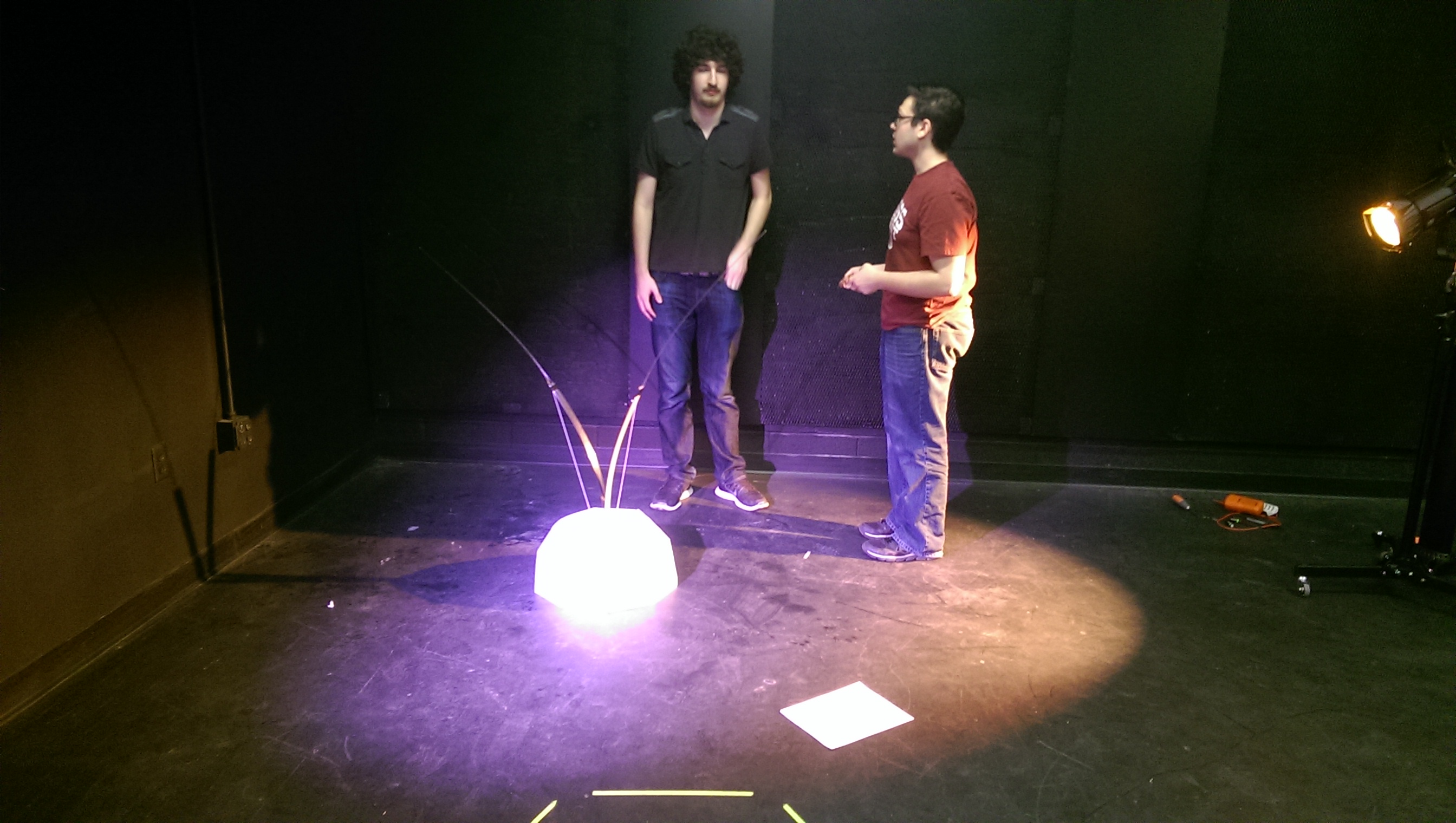
Most people in the world are fairly familiar with the concept of an actor: a person who stands on the stage and delivers a story in some form. The same group of people is typically familiar with the concept of a robot: a mechanical object that performs a task autonomously. In both of these cases, there is a certain set of rules regarding appearence, movement, tasks, shape, scale, and so on that are generally used to define these objects. In more recent years, the theatre community has begun to accept robots into the theatrical setting, however these adaptations are rarely seamless. In many cases, the actors act as we expect actors to act, and the robot behaves like a robot should. But what happens when we attempt to bring a robot into a theater as an actor? Can it still look like a robot? Can it act like a robot? Can the actors interact with it like a machine?
Columbina’s Companion was an experiment in how to seamlessly integrate a robot into a show. We attempted to merge certain aspects of a classical robot with certain aspects of a classical actor to create a true “robot actor”.
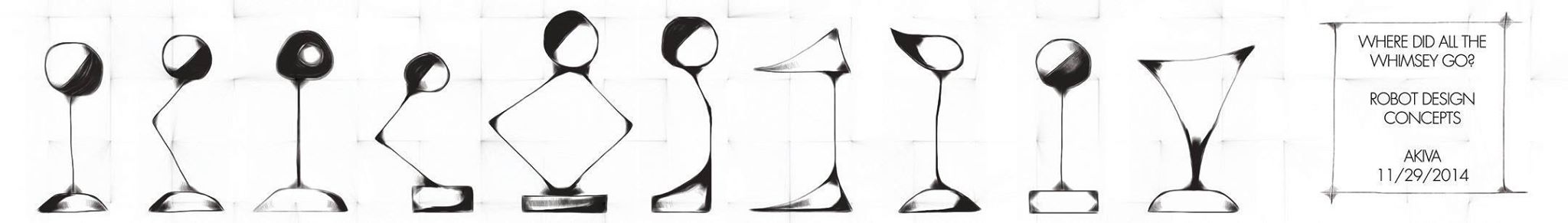
Several ideas for non-robotic form.
Video
Below is a video of Columbina’s Companion’s debut performance
Technical Notes
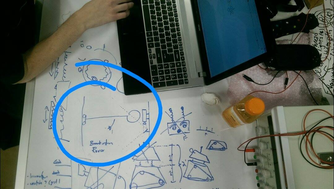
The base of the robot is a Brookestone Rover 2.0
This allowed us easy mobility of the robot. The tank drive gave the robot the ability to carry weight and move in a more organic way. It also provided a wireless (WiFi) platform, allowing the robot to roam freely around the theater. The mobility of the robot is human controlled, rather than autonomous. This is similar to an actor; the puppeteer (the director) can tell robot (actor) where to go in the physical space.
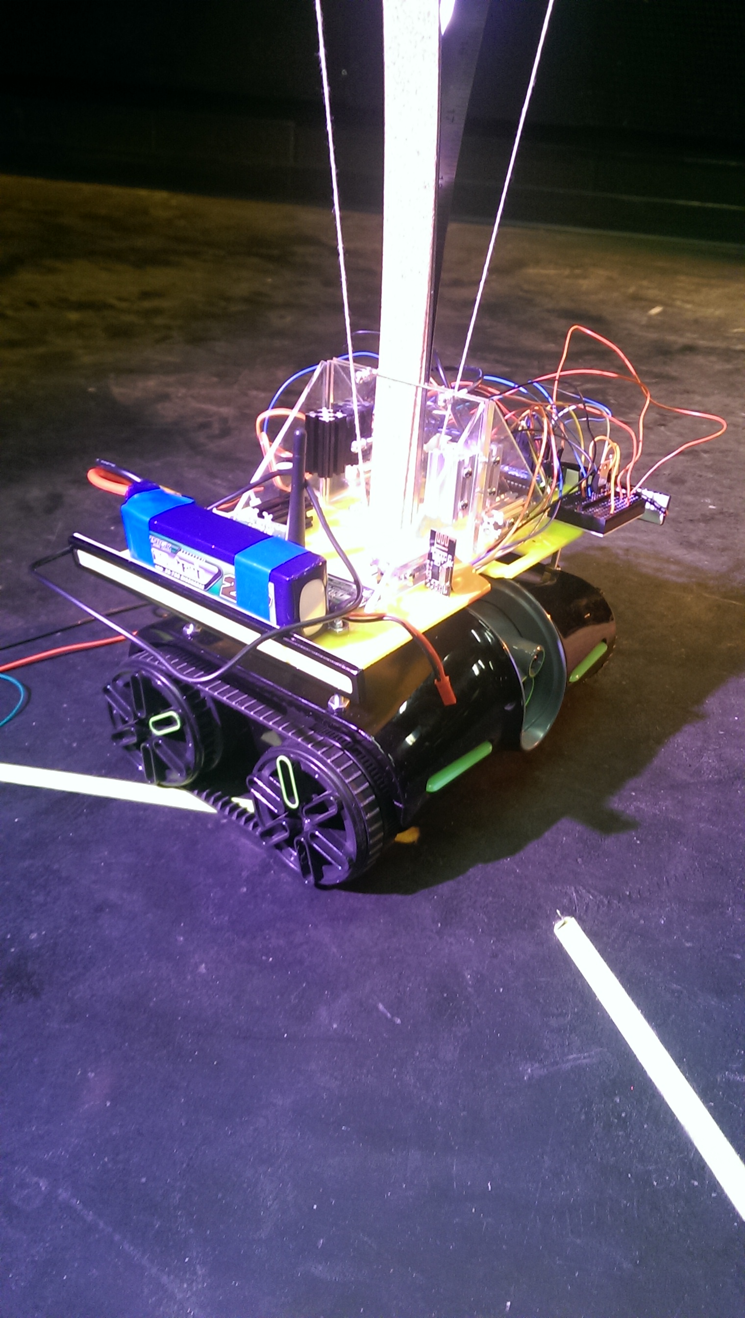
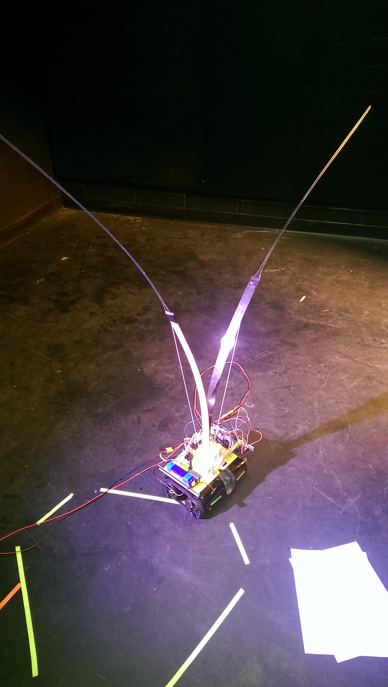
The arms of the robot are two 24″ bendy rulers attached to servos so they could bend at will and independently. These arms are one of two main expressive components of the robot. They were also controlled wirelessly, Arduino to Arduino using NRF2L01+ chips, and were controlled by the puppeteer. Future versions may allow this to be autonomous in response to some sort of stimulous. This is similar to an actor developing his or her own emotional responses to the action on stage.
The lights on the side of the robot are tied in with the arms, but may have similar autonomy in the future.
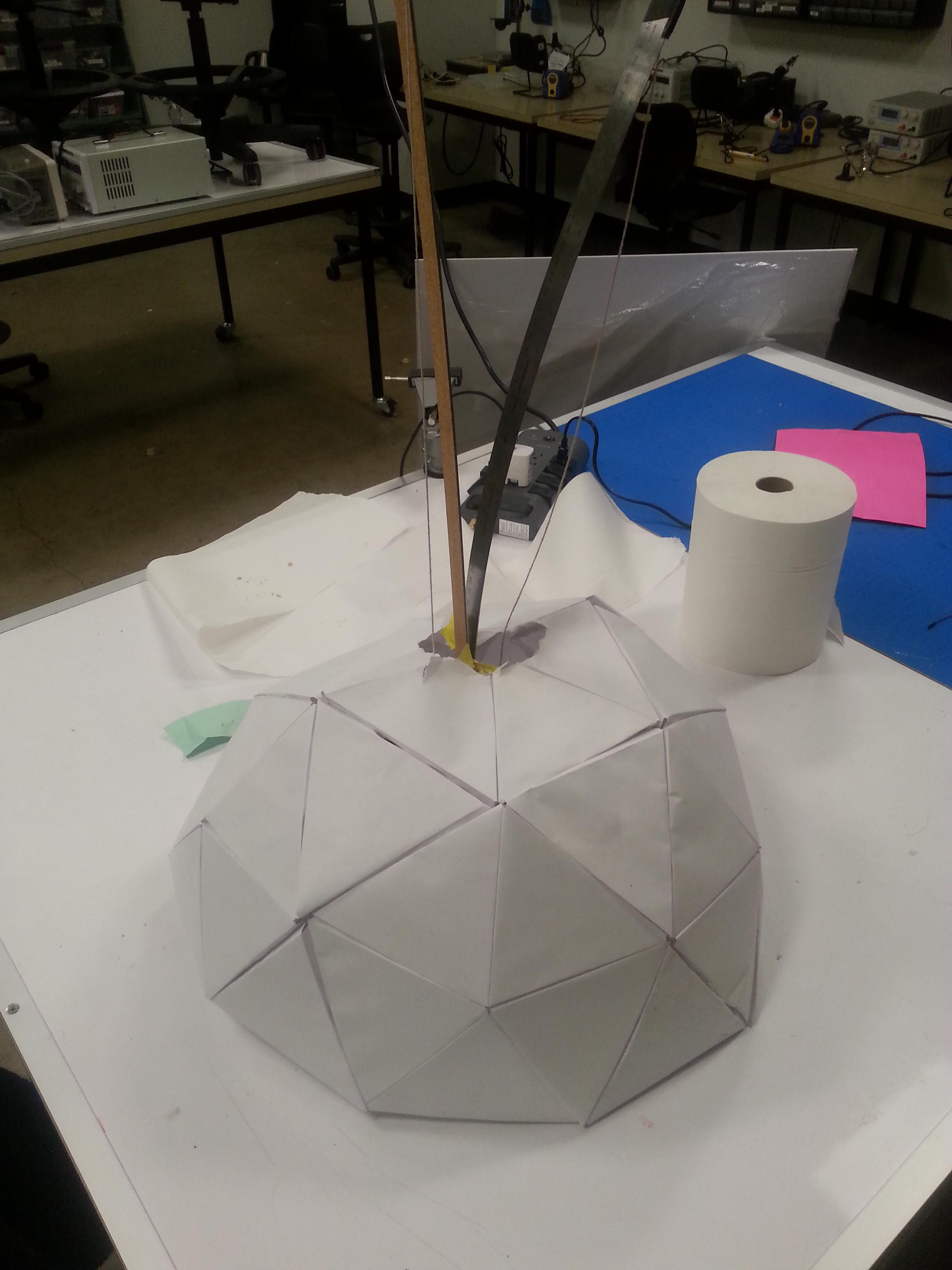
The shell we created was also a significant design factor. We decided to make a geodesic dome out of paper for the shell. The many facets and faces of this shape, as well as the multidirectionality of it created a mistique about the robot, and geodesica are not a common shape for traditional robots; it is about as far away from traditional humanoid and sci-fi as you can get.
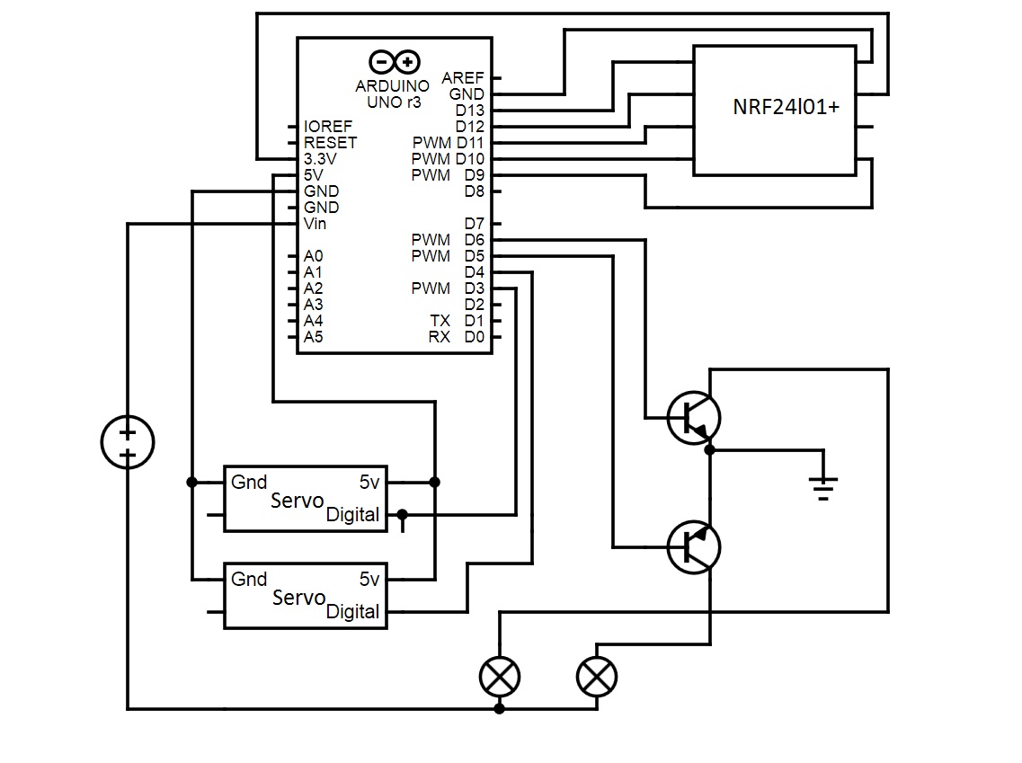
Wiring Diagram
CODE
All of the Arduino code was stock NRF2L01 code for arduino (sending and receiving). They were communicating via a numerical string value: the numbers 0-180 specified a value on one arm servo, 1000-1180 specified degree on the other servo. Stock NRF2L01 code can be found here.
The control was based on a piece of Python software called RoverPylot. The changes came in the main code <“ps3Rover.py”>. We changed the button configuration to listen to the Microsoft XBox controller we had available. We then changed to code to send the values (the strings of numerical numbers that we wanted) to the treads, and added code that mapped the toggle button values to the servos over the Arduinos.
The final Python code (requires OpenCV and PyGame) are here:
#!/usr/bin/env python
”’
whimsybotv2.py was edited by Ruben Markowitz, Bryan Gardiner, and Akiva Krauthamer.
ps3rover.py Drive the Brookstone Rover 2.0 via the P3 Controller, displaying
the streaming video using OpenCV.
Copyright (C) 2014 Simon D. Levy
This program is free software: you can redistribute it and/or modify
it under the terms of the GNU Lesser General Public License as
published by the Free Software Foundation, either version 3 of the
License, or (at your option) any later version.
This program is distributed in the hope that it will be useful,
but WITHOUT ANY WARRANTY without even the implied warranty of
MERCHANTABILITY or FITNESS FOR A PARTICULAR PURPOSE. See the
GNU General Public License for more details.
”’
# You may want to adjust these buttons for your own controller
BUTTON_GDRIVE = 8 # Select button toggle G-Drive
BUTTON_QUIT = 9 # Start button quits
BUTTON_LIGHTS = 0 # Square button toggles lights
BUTTON_INFRARED = 2 # Circle button toggles infrared
BUTTON_CAMERA_UP = 3 # Triangle button raises camera
BUTTON_CAMERA_DOWN = 1 # X button lowers camera
SERIAL_PORT = 8 # Arduino Com Port
# Avoid button bounce by enforcing lag between button events
MIN_BUTTON_LAG_SEC = 0.5
# Avoid close-to-zero values on axis
MIN_AXIS_ABSVAL = 0.1
import rover
import cvutils
import time
import pygame
import sys
import signal
import serial
“””
# Converts Y coordinate of specified axis to +/-1 or 0
def _axis(index):
value = -controller.get_axis(index)
if value > MIN_AXIS_ABSVAL:
return value
elif value < -MIN_AXIS_ABSVAL:
return value
else:
return 0
# Handles button bounce by waiting a specified time between button presses
“””def _checkButton(controller, lastButtonTime, flag, buttonID, \
onRoutine=None, offRoutine=None):
if controller.get_button(buttonID):
if (time.time() – lastButtonTime) > MIN_BUTTON_LAG_SEC:
lastButtonTime = time.time()
if flag:
if offRoutine:
offRoutine()
flag = False
else:
if onRoutine:
onRoutine()
flag = True
return lastButtonTime, flag”””
# Set up controller using PyGame
pygame.display.init()
pygame.joystick.init()
controller = pygame.joystick.Joystick(0)
controller.init()
# Create a PS3 Rover object
rover = PS3Rover()
# Defaults on startup: lights off, ordinary camera
lightsAreOn = False
infraredIsOn = False
# Tracks button-press times for debouncing
lastButtonTime = 0
# Set up signal handler for CTRL-C
signal.signal(signal.SIGINT, _signal_handler)
# Loop till Quit hit
while True:
# Force joystick polling
pygame.event.pump()
“”” # Quit on Start button
if controller.get_button(BUTTON_QUIT):
break
# Move camera up/down
if controller.get_button(BUTTON_CAMERA_UP):
rover.moveCamera(1)
elif controller.get_button(BUTTON_CAMERA_DOWN):
rover.moveCamera(-1)
else:
rover.moveCamera(0)
“””
# Set treads based on axes
rover.setTreads(_axis(1), _axis(3))
serialSender.write(str(int(abs(_axis(4))*180))+”\n”)
time.sleep(.005)
serialSender.write(str(((180-int(abs(_axis(0))*180))+1000))+”\n”)
time.sleep(.005)
# Shut down Rover
rover.close()
The rest of the RoverPylot library can be downloaded from the above link.
The Send Arduino code used is as follows:
#include <SPI.h>
#include <RF24.h>
#include “printf.h”
//
// Hardware configuration: first MSP430, then ATMega
//
#if defined(ENERGIA)
#if defined(__MSP430FR5739__)
# define CE P1_2
# define CS P1_3
# define ROLE P2_5
#elif defined(__MSP430G2553__)
# define CE P2_1
# define CS P2_0
# define ROLE P2_2
//#elif defined(__LM4F120H5QR__)
//# define CE PA_6
//# define CS PB_5
//# define ROLE PA_5
#endif
# define BAUD 9600
#else
# define CE 9
# define CS 10
# define ROLE 7
# define BAUD 57600
#endif
RF24 radio(CE, CS);
unsigned long integerValue;
unsigned long incomingByte;
//
// Topology
//
// Radio pipe addresses for the 2 nodes to communicate.