10.1. 16-223 Practicum Exam 2016: Binary Decoding
Please write your name here:
Please quickly read through all the instructions before beginning.
10.1.1. Objective
Implement a binary numeric input and three separate readouts of the value, using only parts from your class kit. The requirements for the device are specified in some detail below.
Once you have physically built, programmed, and tested your device, please call over one of your instructors for live testing. We recommend that you use time spent waiting for review to complete the documentation portion. One caution: if you get stuck debugging, please consider when to stop and complete the documentation.
10.1.2. Summary Diagram of Demo
10.1.3. Rules
- Use only parts from your class kit, including an Arduino. If you are missing a necessary part, we have a limited supply of spares; please raise your hand to request a replacement.
- You will need a laptop to program your Arduino and display serial output; you may use your own or a cluster machine.
- You may freely consult your notes, books, the course web site, or any online sources. You may freely use code or circuit examples that you find from these resources. You are not required to cite sources.
- You may not consult your classmates or any other person. No collaboration of any kind is permitted whether in-person or via website, email, chat or other digital means.
- If you have a question, raise your hand and we’ll swing by. Good luck!
10.1.4. Procedure
The first step is to build a circuit on your breadboard which implements the following inputs and outputs for your Arduino: four switches, four LEDs, and a hobby servomotor. We will also observe the Arduino IDE serial monitor output on your laptop screen. Please observe proper circuit practices as we have previously discussed in the exercises.
Electrical Implementation
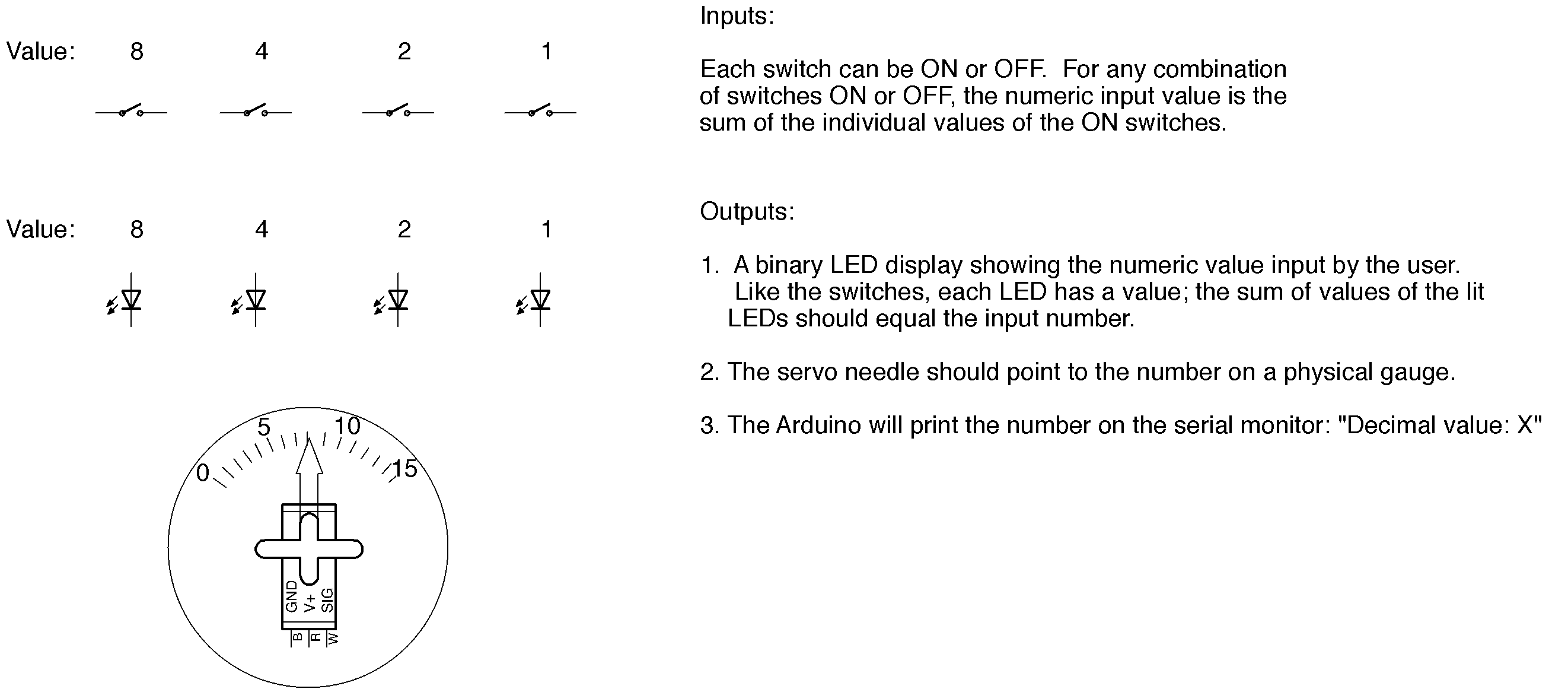
Please build a circuit with four switches arranged in a row which will be used as a binary numeric input to your Arduino. The switches may be momentary (like a pushbutton) or stable (like a slide switch), or some combination of these. They should be arranged physically so that they can be easily manipulated by a user.
Each switch has a different value: in order from left to right, they are valued 8, 4, 2, and 1. The total value of the input is the sum of the values of the active switches. For example, if a user operates the rightmost switch and none of the other switches, then the total of the switches equals the binary value 0001, equivalent to 1 in decimal notation. If the user turns on switches 8, 4, and 1 (leaving 2 off), the value is then 1101 in binary, which is 13 decimal. If this is unfamiliar, a complete table of equivalent 4-bit binary and decimal is provided below.
Please build a circuit with four LEDs in a row to be used as a binary numeric output. Like the switches, these will have values 8, 4, 2, and 1 when read from left to right. These must be software-controlled, not simply wired directly to the switch circuits.
Please attach the blue micro-servomotor from your kit to be powered and controlled by the Arduino. We will supply you with a cardboard gauge cutout and a cardboard arrow to attach to a servo horn and place on the output shaft. The servomotor will be used as a numeric output by pointing to a value on the gauge.
Programming
The second step is to program and test the software to run the demo. We recommend that you start with an existing sketch and modify it; this will help avoid a number of potential trivial errors.
The machine has three different outputs that all run simultaneously, with a display updated no less often than 10 times per second. The sketch should implement the following:
Serial monitor feedback. The Arduino IDE serial monitor should continously display the message “Decimal value: X” where X is a decimal value between 0 and 15 decoded from the input switches. Each update should appear on a new line and appear similar to this sample:
Decimal value: 0
Decimal value: 0
Decimal value: 4
Decimal value: 4
Decimal value: 4
Decimal value: 4
Decimal value: 12
Decimal value: 12
Binary LED display. The four LEDs should continuously display the binary form of the input value, with a lit LED indicating a one and a dark LED indicating a zero for each position.
Numeric pointer display. The servo with attached pointer should continuously indicate the input value. Please calibrate the output position sufficiently to avoid confusion, i.e., point close enough to the correct number the reading is unambiguous.
Testing and Demonstration
- Please carefully test your sketch. Please make sure your switches are firmly seated and easily accessible to the instructors for testing. Please make sure the Arduino IDE serial monitor is clearly visible on your laptop screen.
- When you are ready for review, please raise your hand. An instructor will photograph your breadboard and test your circuit. Please place your test paper with your name adjacent to your breadboard so your name is clearly visible in the photograph.
- If your instructors find a flaw in the implementation, you will be given one try to correct your result, with some loss of points. Please test carefully.
- If you run out of time, we will test what you have completed and award partial credit as appropriate. However, if the end is approaching, please make a careful allocation of time between debugging and completing the documentation.
Documentation
The final step is to document your work.
- Please hand-draw a schematic of your circuit on the back of this page, following the graphic conventions you have been seeing in the exercises. The Arduino can be simplified to a box including only the pins actually used by the circuit. Be sure to carefully label each pin and component value; the schematic should have enough detail that someone skilled in the art could exactly replicate your circuit topology. Note that it is not necessary to show the breadboard layout, only the schematic symbols and connections.
- Please email a copy of your .ino sketch file to garthz@cmu.edu as an attachment.
10.1.5. Grading
Full credit: The machine works exactly as specified and is constructed using solid technique. A user can arrange the switches/buttons in any configuration and observe the correct binary value displayed on the servomotor gauge, the same same value shown in the serial output, and the appropriate LEDs lit. The machine updates continuously so any button/switch changes immediately take effect. The schematic is detailed and the circuit follows good practices.
Partial credit:
| 15% | switches wired properly |
| 15% | LEDs wired properly |
| 10% | serial feedback working (formatted as specified) |
| 20% | servomotor “gauge” points to correct position |
| 30% | compilable Arduino code that satisfies the prompt |
| 10% | schematic is accurate and legible |
10.1.6. Extra Challenge
If you finish early, you may attempt the following challenge for up to five bonus points:
Add an additional switch that changes the mode of the device into a multiplier instead of an adder. If the switches for 8 and 2 are on, for instance, the outputs should read 16. (Note that switches that are off should default to 1 rather than 0 in multiplication mode.) Note that the normal input mode should also still be operable. Hint: you may also need more LEDs and a modified scale.
10.1.7. Reference
The following table includes all four-bit binary numbers and the corresponding decimal value:
| four-bit binary digits | decimal value |
|---|---|
| 0 0 0 0 | 0 |
| 0 0 0 1 | 1 |
| 0 0 1 0 | 2 |
| 0 0 1 1 | 3 |
| 0 1 0 0 | 4 |
| 0 1 0 1 | 5 |
| 0 1 1 0 | 6 |
| 0 1 1 1 | 7 |
| 1 0 0 0 | 8 |
| 1 0 0 1 | 9 |
| 1 0 1 0 | 10 |
| 1 0 1 1 | 11 |
| 1 1 0 0 | 12 |
| 1 1 0 1 | 13 |
| 1 1 1 0 | 14 |
| 1 1 1 1 | 15 |
10.1.8. Test Paper
The following document was provided on paper on test day: practicum-2016.pdf
10.1.9. Grading Rubric
Note: the following rubric was not provided to students prior to the test.
| Possible Points | Practicum Rubric |
|---|---|
|
|
| 3 | either pull-up or pull-down resistor is in use |
| 3 | inputs cannot float for any physical state |
| 3 | bias resistance value is reasonable (roughly 330 ohm to 100K) |
| 3 | placement is in correct digit order |
| 3 | all switches function |
| Comments | |
|
|
| 3 | LEDs wired in correct direction to either ground (active-high) or VCC (active-low) |
| 3 | ballast resistor is in series with LED |
| 3 | ballast resistor has reasonable value |
| 3 | placement is in correct digit order |
| 3 | all LEDs function |
| Comments | |
|
|
| 3 | serial stream generated |
| 3 | values are correct |
| 2 | text is correctly formatted |
| 2 | the refresh rate is at least 10Hz |
| Comments | |
|
|
| 3 | servo wired properly |
| 2 | indicator is firmly mounted |
| 5 | the servo shows a value proportional to input |
| 5 | indicator moves smoothly without extraneous jumps |
| 5 | the numbers are clearly indicated over the full range |
| Comments | |
|
|
| 3 | digital pin modes initialized |
| 3 | Servo library invoked and Servo object initialized |
| 3 | Serial port initialized |
| 3 | all switches correctly read |
| 3 | sum value correctly computed |
| 3 | all LEDs updated in all conditions |
| 3 | servo correctly updated in all conditions |
| 3 | servo calibration calculation included |
| 3 | value correctly printed to serial port in all cases |
| 3 | the code is well-structured, with legible logic is legible, no unused cases |
| Comments | |
|
|
| 2 | symbols are conventional |
| 2 | wire crossing versus joining is consistently indicated |
| 2 | no dangling wires; all nodes are connected |
| 2 | circuit matches photograph of breadboard and code |
| 2 | LEDs drawn in correct orientation |
| Comments | |
| 100 | Total score |