16-223 Introduction to Physical Computing
Evan Hill and Philip Baker
Project Description
With this project, children will create their own paper airplane and then participating in a flying simulation. Children will create a paper airplane and attach it within the wind tunnel. Using a yoke on the outside of the tunnel, they will be able to ‘steer’ their plane by altering the direction of wind flow. We will enable kids to see the flow of wind around their plane by allowing fog from dry ice and water to flow through the tunnel. We plan to include changing light displays as well. Children love to create and we believe that seeing their own creations come to life in a setting they are not often exposed to will capture and hold their attention.
The preferred installation location for the interactive paper airplane wind tunnel is in the garage at the museum. The garage focuses on things that drive, fly, and roll, and has areas for children to build. Our project involves creating a physical plane and testing its flight so it would be a good fit for the garage space.
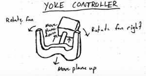
A typical visitor experience would begin with the participant creating a paper airplane of their own design. Then the nose of the plane would be hole punched to allow for the plane to be attached in the wind tunnel. Once the plane is placed in the wind tunnel and attached to the fishing line support, the participant would be given control of the yoke to simulate flying their paper airplane. Turning or the yoke would correlate to the fan rotating, pushing down on the yoke would move the plane toward the bottom of the wind tunnel, and pulling up would cause the plane to move toward the top of the wind tunnel. As the participant is flying the plane, lights will change as the plane lifts off the ground, and the plane may encounter artificial turbulence or thunderstorms. A successful interaction would be a participant creating plane that flies smoothly, or the improvement of a participant’s design over multiple trials.
Technical Outline
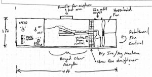
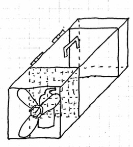
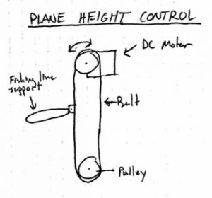
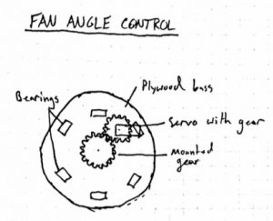
The first step is to construct the wind tunnel and install the fan, the straws to straighten the flow, and the fishing line to hold the nose of the plane. This basic setup would allow us to see how well paper airplanes perform in the wind tunnel. We would be able to identify possible problems with the system such as fan speed variation, airplane flight, and airplane design. The next step would be to add a belt drive to control the height of the airplane and a servo-driven rotating base to turn the fan. Both of these mechanisms would be connected to an Arduino and laptop with a yoke controller. Finally, the sensors and lights for the reactive display and simulated thunderstorms would be installed.
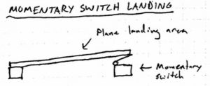
The main body of the wind tunnel will be constructed out of plywood and the paper airplane chamber will be made out of clear acrylic to allow for viewing. A simple household fan will be used and a grid of straws will be used to straighten the flow. Two pulleys and a belt driven by a DC motor will move the fishing line support for the plane up and down. This motion will be scaled to the up and down motion of the yoke controller. A rotating base made out of plywood mounted on bearings would be driven using a servo and gear system. The angle of the servo is going to be scaled to the rotation of the yoke controller. A momentary switch at the bottom of the wind tunnel will monitor whether the plane is on the ground and will control a light display. Randomized turbulence and thunderstorms will be created using lights and by quickly changing the fan angle or plane height.
Project Management
For the proof of concept demonstration we hope to have a wind tunnel that a plane is able to fly within. We believe that once we have proven that the attachment mechanism works and flight is possible, we will be able to effectively implement the ‘steering’ of the plane. For the first on site test, we hope to have the project be completely functional, but not yet aesthetically completed. The attachment mechanism used may need to be adjusted for the proof of concept model. The fog injection mechanism is another area of potential concern. We plan on using a flexible hose extending from a container, but to ensure that the source of fog moves in unison with the steering of the plane we will need to run trials on a working model.
Budget Outline
| Material | Quantity | Cost |
| Clear acrylic | 1’ – 2’x4’ | $15 |
| Plywood | 2’x4’ ⅛” | $10 |
| Straws | 500 | $5 |
| Hinges | 2 | $1 |
| Handle | 1 | $2 |
| Dry ice | 1 lb. | $1 |
| Clear tubing | 1 ft. | $2 |
| Fan | 1 | Already owned |
| Fishing line | 1 ft. | Already owned |
| DC motor | 1 | Already owned |
| Servo | 1 | Already owned |
| Pulleys | 2 | $2 |
| Belt | 1 | $0.75 |
| Bearings | 6 | $9 |
| Arduino | 1 | Already owned |
| Momentary switch | 1 | Already owned |
| LEDs | 8 | Already owned |
| USB yoke controller | 1 | $100 |
Total Cost: $147.75
Because the yoke controller is so expensive, we will first try to find one to borrow possibly from lending. If there is not one to borrow we may try to rent one or construct a simplified controller.
Total Cost Without Controller: $47.75
Timeline
- Proof-of-concept test to clarify known unknowns. – 10/30
- Design of custom parts. – 11/01
- Purchasing of special materials or parts. – 10/30
- Fabrication of custom parts. – 11/06
- Mechanical and electrical assembly. – 11/09
- Programming. – 11/15
- Lab testing and debugging. – 11/22
- On-site testing – 12/02
Sketches
Leave a Reply
You must be logged in to post a comment.