Project Proposal: Tricky Ball Drop
 This project allows children to build their own ball drop by turning gears to change the path a ball will take. Barriers will be mounted to each gear, thus turning them will determine the track the ball falls takes. What the children don’t initially know is that some of the gears respond to their actions. These gears function like timers and will rotate on their own after a time period determined by how many rotations the wheel has undergone. In other words, this time interval is determined by how far the motor is manually turned by the children. So, as the rotation of the gear in one direction increases, the pause time before the gear reorients increases. Sound and light warnings will alert the children that the gear will begin moving. Tricky Ball Drop will be designed as a race course and children will be able to send balls down the track. However, we anticipate that many of the children, especially the younger ones, will be more interested in the physical movement and hands-on interaction. Therefore, the delight and wonder of this piece will come from playing with the gears and the surprise that they can move on their own. The proposed site for this project is the Garage, in the space near the spiral slide and wind turbine machine.
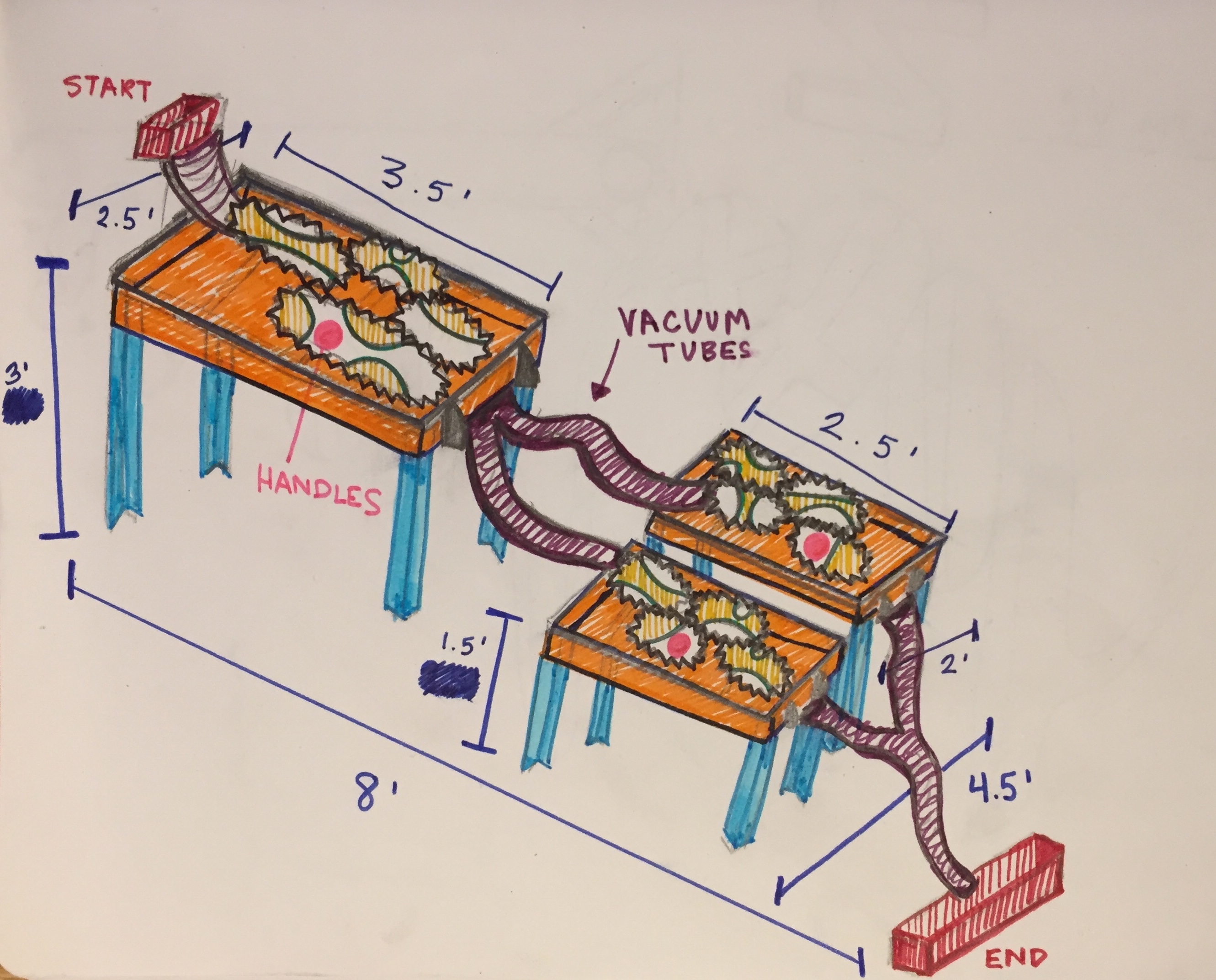
Visitors will enter the Garage and the bright colors of the Tricky Ball Drop will lure them over. The gears, with large, colored handles will suggest to the children that they can play and interact with the piece. The balls, which will be collected at the end of the track, will be accessible from a container on the floor. The project, designed to simulate a race course, will have a clearly denoted a starting box. After the children spend a minute playing with the balls and changing the gears, we anticipate that they will be inclined to race their ball down the track. While interacting with the piece, we expect the children to notice that the gears begin to move without being touched. This is what makes the Tricky Ball Drop “tricky.” When a child drops a ball into the starting box, they will watch it roll down the track, but sometimes the track will move as the ball is going down it. If this happens, we think that the children will want to try again. Perhaps, after some time, they will figure out that they can change the time interval of the moving gear by rotating the wheel more or less.
Our main goal is to encourage hands-on interaction and generate surprise. We expect the children to respond with slight frustration when the gears move without their approval. However, the goal is that the children turn this unexpected movement into a game or race against the machine. Some may figure out that the time interval before the machine moves is related to how many times they rotate the gears. If this happens, we think that the children will build a race course that stays still while the ball travels through it.
Technical overview
The most difficult technical component is designing and building a gear, or group of gears, that can be turned manually and by a motor and to be able to keep track of how many rotations the gears have made. Other challenges include designing a course that the balls tend to not fall out of and designing against the balls getting stuck in the course.
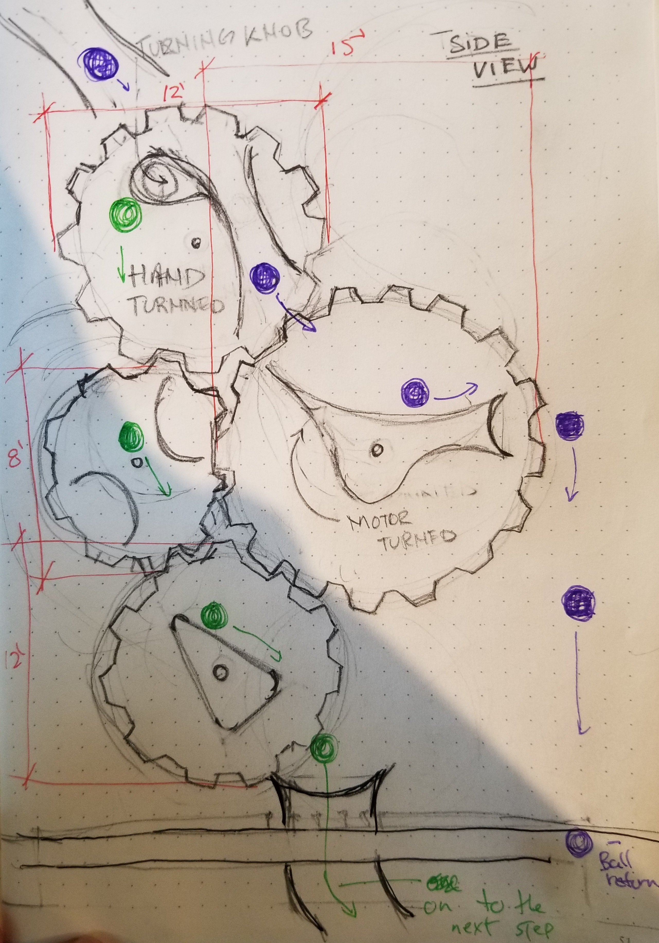
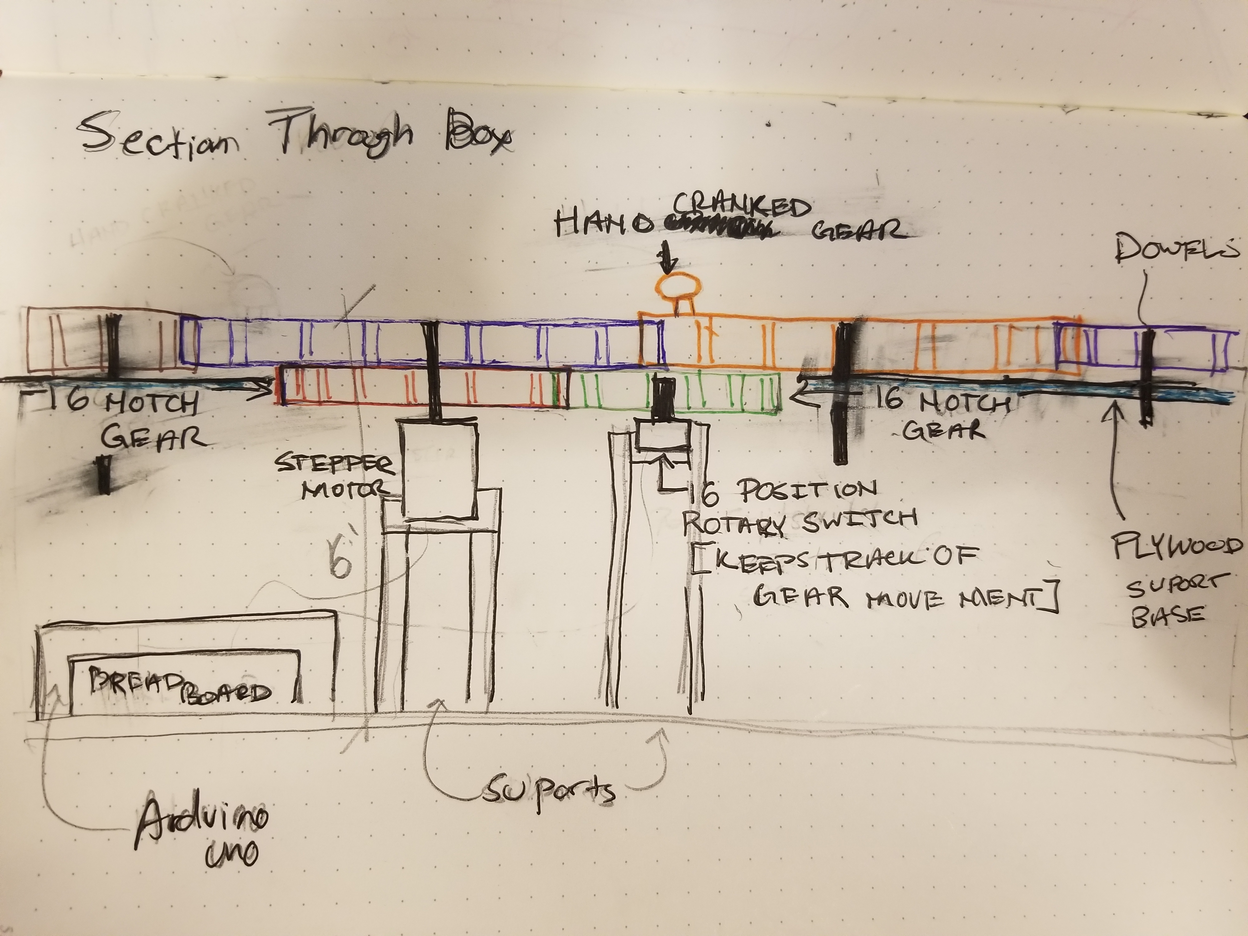
Our approach to building a gear system that keeps track of how many times a gear has been turned uses a 16 position rotary switch. This switch will be mounted to the underside of one of the gears, though not the one that is attached to the motor. The technical nature of the rotary switch will allow us to determine which position the switch is in. We will use this data to determine how long the gear will rest until it begins to rotate on its own.
To make the gears rotate on their own we will be using a stepper motor. A stepper motor is essential because our gears will need to rotate in both directions. We will need to test if the stepper motor can be turned when it is not in use because the children will been turning the gears manually and will not know that the motors exist.
We will be using an arduino in each of the three sections of the piece. The arduinos will be mounted to the bottoms of the structures that hold the gears and will be powered by a battery supply.
Other technical components include wiring the LED strips and speakers. These will be used to alert the children that the gears are getting ready to move on their own. We will have to figure out how to control and LED strip with the arduino.
Milestone Objectives
- Proof of Concept:
-
- The main objective of the proof-of-concept is to verify that we can record a child’s movement of the rotation of the gears and use that to affect how the machine will react.
- We will make a motor controlled gear and a rotation counter. It will interact with a hand spun gear that will be the main input for the device. We will program it in 3 to 4 ways to show how a child’s interaction can have different effects on the machine.
Phase 1 On-Site Test:
-
- One section the the tricky ball drop will be made. This will have more gears that will spin with hand and motor turned gears. Children will be given a ball to put into the machine and test it.
Project management
*These are our main responsibilities in the project but we will be helping each other with all steps.
Annabelle:
- CAD Modeling
- Laser cutting
- Assemblage of the structure
- Coding lights and sensors
- Purchasing wood
Zach:
- Assemblage of gear networks
- Assemblage of the Track
- Coding gear motors
- Wiring motors, sensors, and lights
- Purchasing balls
- Checking out motors
Bill of Materials
| Quantity | Part Name | Description |
| 3 | Bottom panel | Custom cut ½ inch thick plywood |
| 3 | Side panel left | Custom cut ½ inch thick plywood |
| 3 | Side panel right | Custom cut ½ inch thick plywood |
| 3 | Back panel | Custom cut ½ inch thick plywood |
| 3 | Front panel | Custom cut ½ inch thick plywood |
| 12 | Legs | Custom cut ½ inch thick plywood |
| 5 | Tubes | Clear tubing form a vacuum cleaner |
| 12 | Gears | Custom laser-cut ¼ inch plywood |
| 1 | Wood glue | Elmers wood glue |
| 12 | LED strips | 3 ten foot strips |
| 2 | Speakers | 8 ohm speakers |
| 12 | Gear shaft | ¼ inch plywood dowel |
| 4 | Rotary switch | 16 position rotary DIP switch |
| 1 | Red paint | 32 fluid oz can of acrylic paint |
| 1 | Orange Paint | 32 fluid oz can of acrylic paint |
| 1 | Yellow Paint | 32 fluid oz can of acrylic paint |
| 1 | Green Paint | 32 fluid oz can of acrylic paint |
| 3 | Handles | Rotating handle |
| 1 | Box | ¼ inch custom laser-cut plywood |
| 6 | Ball | 2 inch diameter racquetball balls, multicolor |
Budget
| Amount | Description |
| $30 | ½ plywood sheets |
| $12 | ¼ plywood for gears and box |
| $8 | Rotating handles |
| $10 | Vacuum tubing |
| $3 | Wood glue |
| $9 | Rotary switches |
| $16 | Paints |
Estimated Total Cost: $88
*We will split excess out-of-pocket expenses equally
Timeline
Week of October 22:
- Turn in project proposal
- Revise project proposal
- Figure out how to configure gears, rotary switch, and motor
- Check out 3 stepper motors
- Check out one arduino
- Laser cut gears for proof-of-concept prototype
- Assemble proof-of-concept prototype
- Submit proof-of-concept prototype
- CAD model Prototype
- Order wood
- Write sensing code
- Order LED strips
Week of October 29:
- Build housing and structures for the piece
- Laser cut all gears
- Assemble the gear groups with motors
- Connect different sections with tubing
- Write code for LED strips
Week of November 5:
- Finish phase 1 prototype
- On site testing at Children’s Museum
- Debug and edit design based on children’s feedback
- Rebuild/repair main section if destroyed by children.
Week November 12:
- Buy or find paint
- Build other 2 sections
- Paint
Week November 19 (TG):
- If time permits, add speakers
- Debug code
Week November 26:
- Final preparations before final test
- Check out camera equipment for documentation
- Paint and touch up
Week December 3:
- Final project documentation
- Edit photos
- Finish write-up
- Disassemble and clean up
Sketches
Leave a Reply
You must be logged in to post a comment.