Fragment
Alessandra Fleck and Christina Brown
December 5th, 2017
Abstract
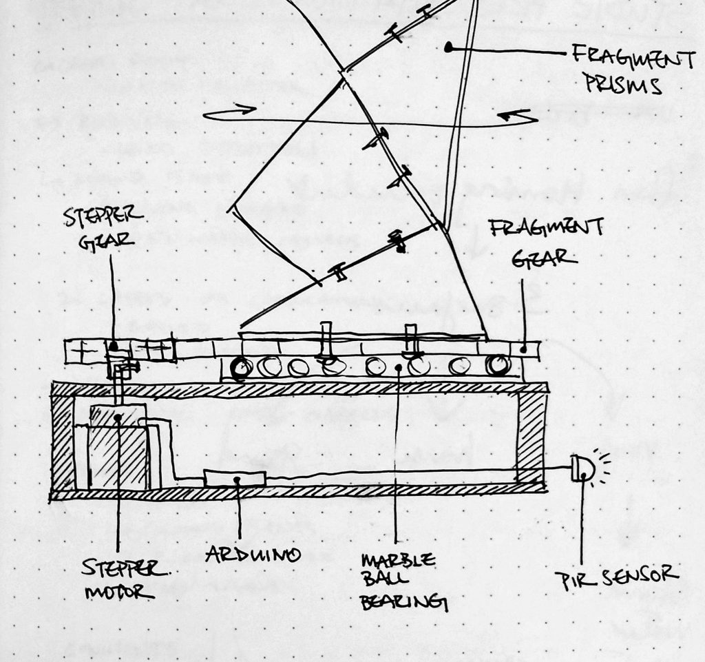
This project aimed to intrigue and inspire curiosity through the fragmentation and movement of light through the activation of a large artistic geometric form in the Children’s Museum lobby. The motion of the piece is affected by two PIR sensors that picks up motion of lobby passerby to add a level of complexity and reaction to its environment that could further inspire curiosity in children. The project involves two main parts- a stepper/gear mechanism with a marble ball bearing to allow for piece activation, and a PIR software system that dictates how the information from the PIR would affect the piece’s movements.
The project was successful in capturing the curiosity of children during our museum installation on Saturday, but the interaction was limited due to the nature of the location. To our surprise, we captured the interest of people from the ledge (close to Maker space/stairs), and perhaps more interaction with people from that space could have been further investigated. The hardware of the project also failed after two hours of operation due to the tolerances of the stepper to gear connection, which made it difficult for the piece to run properly afterwards.
Objectives
The goals of this project ultimately was aimed to rotate a geometrically complex acrylic structure with variation in its motion based off of PIR sensor feedback. In order to achieve this, smaller goals were set:
- Program that takes in PIR input and outputs some kind of variation in the rotation of a stepper motor, when the input is null, the stepper rotates at a constant default rate
- A geometrically complex acrylic structure that can bounce and fragment light into the environment
- Mechanical structure that can translate the stepper rotation into the rotation of the acrylic structure through the use of gears
Implementation
In order to achieve our goals stated above, the following design choices were implemented.
For Software:
- Code that programs the stepper to rotate at a slow constant rate, and then when PIR senses change in environment (caused by motion), it causes the stepper to change direction and rotate at a faster speed for a fixed period of time before going back to its default constant rate and direction
- Wiring of the different components
- Soldering to extend the length of the PIR wires to extend its length to the railing in the lobby
For hardware:
- Wooden stepper shaft to gear connection that is rigid enough to support the high rotation loads
- Stepper gear to Prism Gear connection on a structural base with correct leveling and tolerance to each other to support the desirable motion
- Stepper enclosure that holds the stepper and inset it relative to the gears to allow for the stepper gear and prism gear to be flush with one another.
- Geometric acrylic prisms that are bolted to one another with colorful metallic reflective strips that both fragments light and bounces color, but also visually provides an eye catching piece that is three-dimensionally complex to allow for the light to bounce in a more interesting and less predictable manner
- Marble ball bearing that can minimize the friction in rotation of the acrylic prisms to lessen the amount of power needed in rotating the piece with the stepper motor
Outcomes
Originally the scale of the project was much larger with multiple acrylic prism structures being rotated relative to each other. Unfortunately, the budget and timeline of the project did not allow for us to take on so much (especially considering the expense of the acrylic itself). Thus, the project was scaled down to only have one prism structure that reacted to its surroundings. This decision was ultimately a good choice considering the amount of time, resources, and effort it took to actuate one prism structure, and a larger scale would have increased the chances of failure. The design of the acrylic prisms structure itself however was very successful. Upon it’s completion, no changes/concerns were presented for it was able to fragment light and was visually stunning enough to peak curiosity.
The mechanical design was overall functional, though many tweaks could have been made to make the overall design function more smoothly. The ball bearing had a slight unevenness that occasionally affected the gear to gear connection (only clearly evident when the rotation is at an extremely high speed). The base had to be adjusted/slightly warped to accommodate the unevenness of the ball bearing relative to the uneven distribution of weight in the prism structure itself (due to its geometrically complex form). The stepper rattled against the wooden structure, and caused an almost clock-like sound, which added a mechanical quality to the piece that added character and emphasized the slow rotation of the piece. The stepper shaft to gear connection performed exactly as intended, but after constant wear and tear after a week of testing, the connection had chipped away and broke during the actual museum exhibit, thus cutting our Saturday experience short. Our on site temporary solution of wedging tape into the gap between the stepper shaft and connection piece did not work well, and would only allow for the piece to function for a short while before malfunctioning again.
The software performed as desired, though tweaks could have been made to make the interaction more nuanced, and the overall progression of the code could have been faster to allow for more testing of the overall system along with the code itself. The PIR sensors only provided a fairly binary input, and thus limited the potential for more explicit interaction between the museum visitors and the reaction of the prisms itself.
Contribution
Alessandra:
- First trial of sensor to motion activated device using an ultrasonic sensor and a servo. Discovered that the distance detected by the ultrasonic was too weak and that the servo’s limit in rotation would make it difficult to achieve the smooth motion that was desired
- First basic code and circuit that activates the heavier duty stepper motor
- Investigated various sensors (ultrasonic and IR sensors) as well as writing script and wiring the circuits to test them. Eventually settled upon using PIR, and then researched into how a PIR works
- Purchased PIR sensors and additional Arduino from Amazon
- Purchased 1/4 inch acrylic sheet from dfab (which ended up not being used in the project fabrication)
- Purchased three 12 pack double A batteries along with 4 9V batteries
- Wrote the code to implement PIR input to activate stepper rotation output in code and circuit
- Received gears and a sample prism structure in rhino file from Christina, and created one full prism structure in rhino space
- Code and circuit for a PIR to LED piece that was eventually removed from the final project
- Lasercutted with Christina for half of the geometric prism components
- Code and circuit that programs the stepper to rotate at a slow constant rate
- Quickly put together a LED piece out of lasercut pieces from Christina
- [First Museum Visit]
- Adjusted code so that when PIR senses change in environment (caused by motion), it causes the stepper to change direction and rotate at a faster speed for a fixed period of time before going back to its default constant rate and direction
- Tried to remove calibration time, code failed; reverted back to code with calibration time
- Tried a different way of connecting PIR to stepper in code, ended up reverting back to use of part of Professor Garth’s example on the course website
- Soldering to extend the length of the PIR wires to extend its length to the railing in the lobby
- Added another PIR and more nuances to the stepper rotation
- [Second Museum Trip]
- Creating / Editing documentation video, edit photos, and cleaning up code for final project report
Christina:
- Bought reflective metallic paper from the art store
- First small scale acrylic mock up of individual prism shapes
- Second small scale foamcore mock up of a multiple prism structure with rounded corners and bolt fasteners
- Basic rhino model with the right sized gears and one basic prism structure, which was then given to Alessandra to work on
- Received rhino model with one full structure from Alessandra, reiterated on the rhino model to create three uniquely shaped structures on a gear system, and implemented openings for where bolt connections would occur within that rhino model
- Created a quick grasshopper code rotating the three structures to ensure that the structures will not collide into one another before laying out the lasercut file and reorienting all the pieces to be flat
- Purchased 5 sheets of clear acrylic sheets from dfab
- Lasercut 50% of the acrylic prism structures and two acrylic gears (using 5 sheets)
- Purchased 3 more sheets of orange acrylic sheets
- Lasercut the other 50% of the acrylic prism structures with Alessandra (using 2 sheets, 1 orange acrylic sheet extra)
- Design and construction of the marble ball bearing based on the metal ball bearing found in Ideate (lasercut acrylic and black foamcore)
- Assembling one full acrylic prism structure and laminating each acrylic piece with strips of metallic colorful paper, and then connecting the acrylic structure to the gear
- Creation of a wooden base with elevated marble ball bearing and containment of the stepper motor in the center for the first museum trip (stepper shaft to gear connection provided from Alessandra from her assignment 2 project)
- Scaled down the project from three acrylic structures to one after noticing the time, scale, and budget complications that this project is currently facing (having spent over $100 out of own pocket alone)
- [First Museum Trip]
- Created new wooden stepper shaft to gear connection based off of the CAD file found on ideate website, tested it, piece failed
- Redesigned and created new wooden stepper shaft to gear connection piece from woodshop that is more rigid and durable, and lasercut stepper gear piece with metal tubes as the locking mechanism for the acrylic laminations
- Creation of new base with an lasercut top component that fastens into the stepper motor (CAD file from ideate website) and a lower component created from woodshop that secures the stepper motor and provides space to house the circuits
- After testing in ideate, readjusting the top component of the base by compression one side to accommodate the slight imbalance in the marble ball bearing to minimize potential of gears not touching. This is done by drilling into the top component and screwing a wood screw that pulls together the top and bottom components enough to balance out the mechanical structure
- [Second Museum Trip]
- Editing photos from museum trip, drawing electronic schematic and mechanical drawings for the final project report
project video
photo documentation
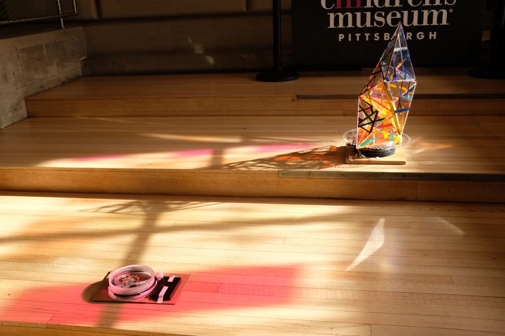
Project Documentation from First Museum Trip Natural lighting was brighter during our first trip, so the effects of our project are more dramatic in this photo
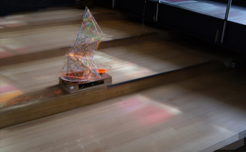
Model photos on site overlaid to highlight the movement and effects of the project
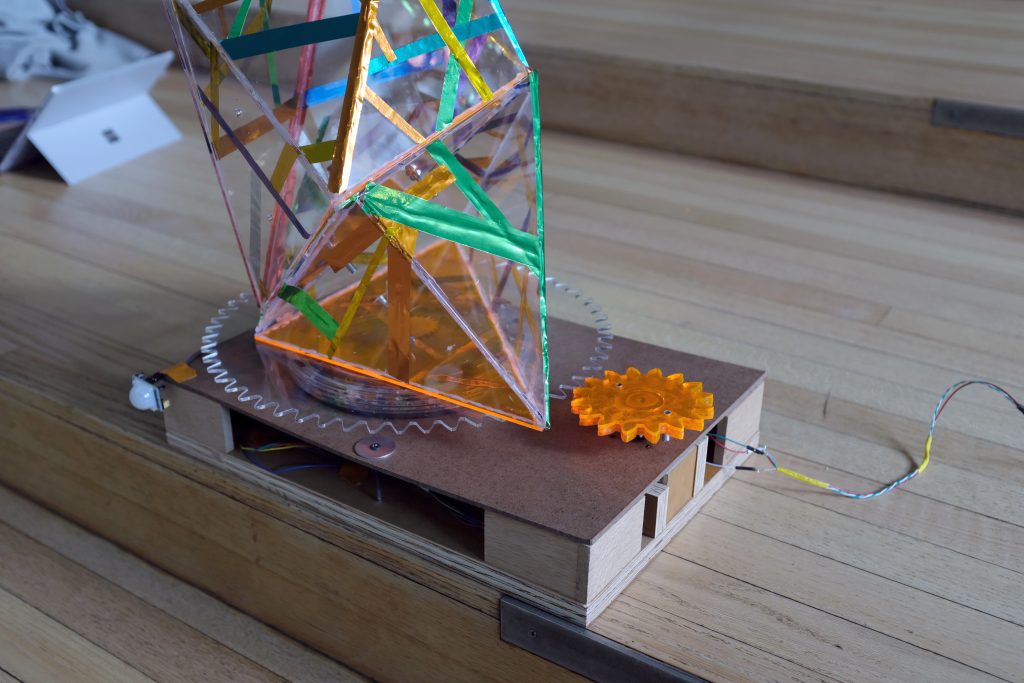
Closer image of the base and mechanism design of the final project
citations
Stepper-Driven Turntable from 16-223 Course Website
supporting material
Electronic schematics
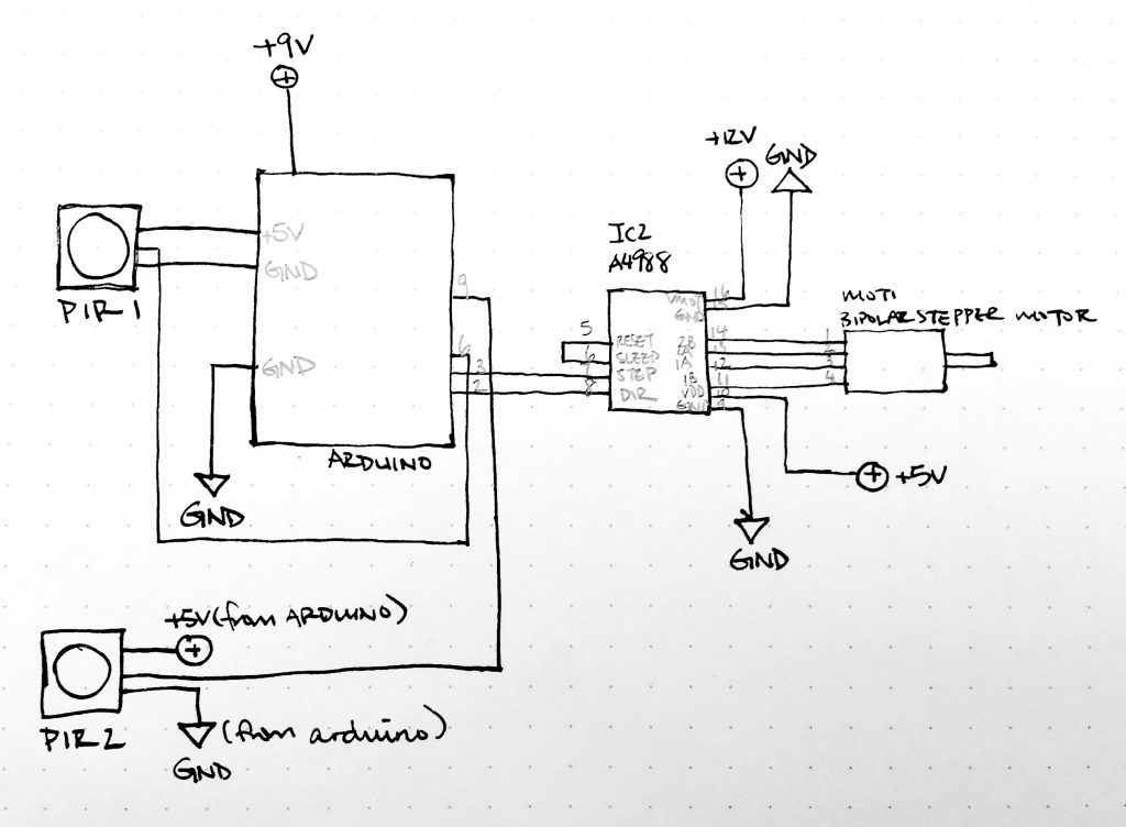
Final Iteration Schematic
Mechanical drawings
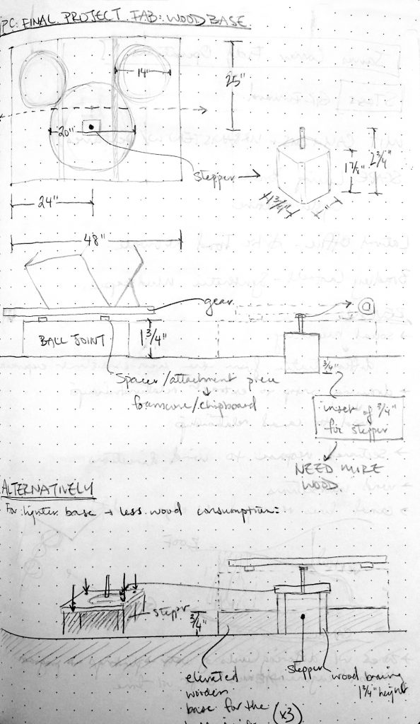
Original Final Project Wood Base
Redesigned Wood Base after first museum visit
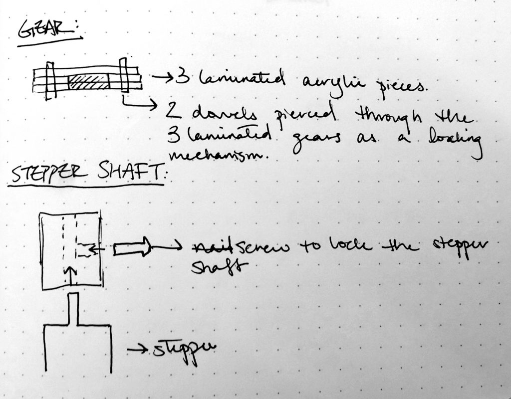
Redesigned stepper gear and stepper shaft after first museum visit
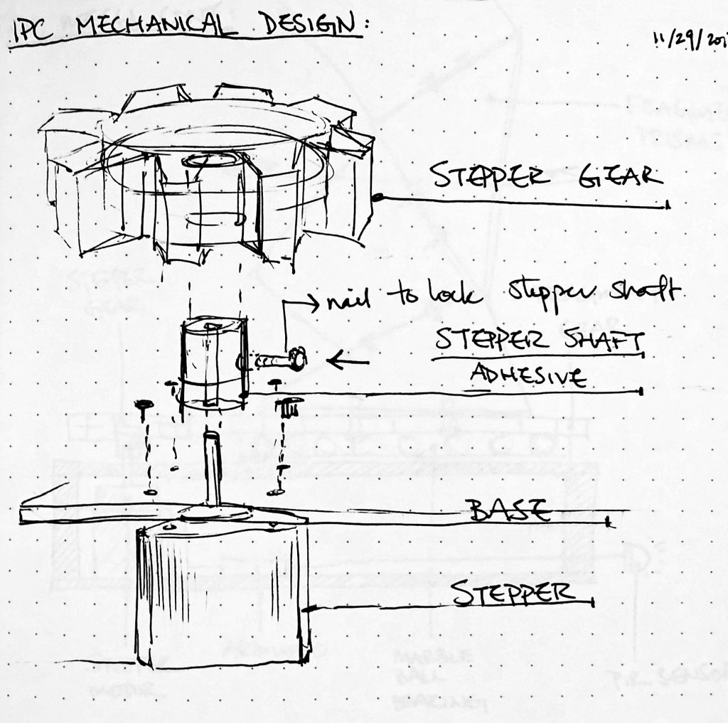
Redesigned stepper connections
Source code
</pre>
//INCLUDE STEPPER LIBRARY FOR USE OF BUILT IN FUNCTIONS
#include <Stepper.h>
//CONFIGURE THE PIR SENSOR
int calibrationTime= 10; //time for sensor to calibrate
long unsigned int lowln; // sensor outputs a low impulse
long unsigned int pause = 5000; //miliseconds the sensor has to be low before all motion is assumed to be stopped.
boolean lockLow=true;
boolean takeLowTime;
// begins assuming no motion detected
// DESIGNATE TWO PIR SENSORS TO SPECIFIC PINS AND STARTS
//set up pin for pir sensor 01
int pirPin = 6; // digital pin 6 connects to PIR output (pir close to the stairs)
int pirPos = 0; // variable for reading pir pin status
//set up pin for pir sensor 02
int pirPin2 = 9; // digital pin 9 connects to PIR_02 output (pir close to the ramps)
int pirPos2 = 0; //variable for reading pir pin status
//STEPPER SETUP AND CONFIGURATION
// StepperSweep - move a stepper motor at different rates
//
// Copyright (c) 2016, Garth Zeglin. All rights reserved. Licensed under the
// terms of the BSD 3-clause license as included in LICENSE.
//
// This program assumes that:
//
// 1. A A4988 (Nema17) stepper motor driver is connected to pins 2 and 3.
// 2. A control potentiometer can vary the voltage on A0.
// 3. The serial console on the Arduino IDE is set to 9600 baud communications speed.
// ================================================================================
// Define constant values and global variables.
//STEPPER PIN DEFINITIONS
// Define the pin numbers on which the outputs are generated.
#define DIR_PIN 2 // The direction pin controls the direction of stepper motor rotation.
#define STEP_PIN 3 // Each pulse on the STEP pin moves the stepper motor one angular unit.
#define ENABLE_PIN 4 // Optional control of the driver power.
// ================================================================================
// Configure the hardware once after booting up. This runs once after pressing
// reset or powering up the board.
void setup(void)
{
//SET PINMODE AND CALIBRATION TIME FOR PIR SENSOR
Serial.begin(9600); //begins serial communication
pinMode(pirPin, INPUT);
pinMode(pirPos, OUTPUT);
digitalWrite(pirPos, HIGH);
//give sensor time to calibrate (this is needed to optimize the accuracy of the sensor)
Serial.println("calibrating sensor");
for(int i = 0; i<calibrationTime; i++){
Serial.print(calibrationTime - i);
Serial.print("-");
delay(1000);
}
Serial.println();
Serial.println("done");
//make sure the PIR output is low (meaning no motion is detected) before ending setup
while (digitalRead(pirPin)==HIGH){
delay(500);
Serial.print(".");
while (digitalRead(pirPin) ==HIGH){
delay(500);
}
}
//PIR HAS COMPLETED SETUP AND CONFIGURATION AND IS READY TO DETECT MOTION
Serial.print("SENSOR ACTIVE");
//SET PINMODES FOR THE STEPPER
// Initialize the stepper driver control pins to output drive mode.
pinMode(DIR_PIN, OUTPUT); //
pinMode(STEP_PIN, OUTPUT);
pinMode(ENABLE_PIN, OUTPUT);
// Drive the /ENABLE pin low to keep the motor always energized.
digitalWrite(ENABLE_PIN, LOW);
}
/****************************************************************/
/// Rotate the stepper motor a specified distance at constant speed. It does
/// not return until the motion is complete, e.g. it 'blocks' for the duration.
///
/// \param steps angular distance to move; the sign determines the direction,
/// but the precise angle depends upon the driver microstepping
/// configuration and type of motor.
///
/// \param speed speed in steps/second
void rotate_stepper(int steps, float speed)
{
// Configure the direction pin on the stepper motor driver based on the sign
// of the displacement.
int dir = (steps > 0)? HIGH:LOW;
digitalWrite(DIR_PIN, dir);
// Find the positive number of steps pulses to emit.
int pulses = abs(steps);
// Compute a delay time in microseconds controlling the duration of each half
// of the step cycle.
// microseconds/half-step = (1000000 microseconds/second) * (1 step/2 half-steps) / (steps/second)
unsigned long wait_time = 500000/speed;
// The delayMicroseconds() function cannot wait more than 16.383ms, so the
// total delay is separated into millisecond and microsecond components. This
// increases the range of speeds this function can handle.
unsigned int msec = wait_time / 1000;
unsigned int usec = wait_time - (1000*msec);
// Print a status message to the console.
Serial.print("Beginning rotation of ");
Serial.print(steps);
Serial.print(" steps with delay interval of ");
Serial.print(msec);
Serial.print(" milliseconds, ");
Serial.print(usec);
Serial.print(" microseconds.\n");
// Loop for the given number of step cycles. The driver will change outputs
// on the rising edge of the step signal so short pulses would work fine, but
// this produces a square wave for easier visualization on a scope.
for(int i = 0; i < pulses; i++) {
digitalWrite(STEP_PIN, HIGH);
if (msec > 0) delay(msec);
if (usec > 0) delayMicroseconds(usec);
digitalWrite(STEP_PIN, LOW);
if (msec > 0) delay(msec);
if (usec > 0) delayMicroseconds(usec);
}
}
// ================================================================================
// Run one iteration of the main event loop. The Arduino system will call this
// function over and over forever.
void loop(void)
{
// Now demonstrate that the stepper can freely rotate.
rotate_stepper(1000, 250.0);
rotate_stepper(-1000, 250.0);
// Now begin a simple back and forth motion with speed controlled by the analog input.
while (1) {
// Read the current value of the potentiometer input from analog input 0.
int an0 = analogRead(0);
Serial.print(an0);
Serial.println("testing speed");
// Map the input to a useful speed range. Last two values are the speeds.
int speed = map(an0, 0, 1023, 15, 20);
//The current speed is set to 15
//CONFIGURE MOVEMENT FOR PIR 1 IS MOTION IF DETECTED AT THE STAIRCASE
//this motion is a 180 degree rotation with a shortstep back 50 degrees, followed by another 180 degree rotation.
//This motion is executed as long as motion is detected in front of pir 1.
if (digitalRead(pirPin)==HIGH){ // motion detected in front of the staircase
Serial.println("in high");
rotate_stepper( 180, speed);
rotate_stepper( -50, speed);
rotate_stepper( 180, speed);
}
//CONFIGURE MOVEMENT FOR PIR 2 IF MOTION IS DETECTED AT THE RAMP
// this motion is a short 100 degree rotation back and forth motion.
if (digitalRead(pirPin2)==HIGH){ // motion detected at the ramp
Serial.println("in high");
rotate_stepper( 100, speed);
rotate_stepper( -100, speed);
rotate_stepper(100, speed);
rotate_stepper(-100, speed);
//CONFIGURE CONSTANT MOVEMENT IF NO MOTION IS DETECTED AT EITHER OF THE TWO PIR'S
}
else {
Serial.println("in low"); //The system has detected no motion
rotate_stepper(-360, speed); //rotate counterclockwise at a constant, slow speed.
}
}
}
/****************************************************************/
<pre>
Leave a Reply
You must be logged in to post a comment.