In this demo I wanted to understand how an analog tool, such as a soft potentiometer could change the color of an RGB Led. I also made an attempt to connect sound through the use of a piezo buzzer in association with a change in the color, but was unsuccessful in the output.
In the demo video the RGB led is not visible. To optimize the ability to notice the change in color I placed a foam cube on top of the led to slow the diffusion of the light.

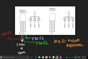
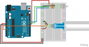
The circuit was created with help from a few websites noted in the code below.
// Help from SparkFun guide to use of a soft potentiometer and HackerScapesBuzzer Reacts to a Specific RGB LED Color//Create a system where a spectrasymbol soft potentiometer changes the color of an RGB light. // setup pins for rgb color constants (Digital Pins) const int SoftPotentiometer_PIN = 0; // Analog input pin a0 const int RED_COLOR= 8; const int GREEN_COLOR= 9; const int BLUE_COLOR= 10; int PIEZO_sound = 12; int PIEZO_value = 0; // Global variables for Pulse with Modulation values of the RGB LED.For interpretation in the rgb function and loop. //PWM controls the LED brightness, the color becomes mixed when dimming in different amounts. int redValue, greenValue, blueValue; void setup() { pinMode(RED_COLOR, OUTPUT); pinMode(GREEN_COLOR, OUTPUT); pinMode(BLUE_COLOR , OUTPUT); pinMode(PIEZO_value, OUTPUT); Serial.begin(9600); // serial communication at bits/second } void loop() { // Soft Potentiometer Value, analog input value ranges from (0-1023) int pValue; pValue = analogRead(SoftPotentiometer_PIN); setRGB(pValue); // set the rgb led color to potentiometer value // or > for (>) and <(<) / & ... syntax??? // some reason the syntax below did not create an "not declared" error message. if (pValue > 0 , pValue <=200) { digitalWrite(PIEZO_value,HIGH);// turn on piezo buzzer sound } else: digitalWrite(PIEZO_value, LOW); // if minimum voltage not recieved or larger, no sound from the piezo buzzer. } // begin setting up sections of the potentiometer for different color "peaks." void setRGB(int RGBposition) { int mapRGB1, mapRGB2, constrain1, constrain2; // (Red at 0 and the midpoint) mapRGB1 = map(RGBposition, 0, 341, 255, 0); constrain1 = constrain(mapRGB1, 0, 255); mapRGB2 = map(RGBposition, 682, 1023, 0, 255); constrain2 = constrain(mapRGB2, 0, 255); redValue = constrain1 + constrain2; // Green at 341 // (one-third of the way to 1023): greenValue = constrain(map(RGBposition, 0, 341, 0, 255), 0, 255) - constrain(map(RGBposition, 341, 682, 0,255), 0, 255); // Blue at 682 // (two-thirds of the way to 1023): blueValue = constrain(map(RGBposition, 341, 682, 0, 255), 0, 255) - constrain(map(RGBposition, 682, 1023, 0, 255), 0, 255); analogWrite(RED_COLOR, redValue); analogWrite(GREEN_COLOR, greenValue); analogWrite(BLUE_COLOR, blueValue); }
Leave a Reply
You must be logged in to post a comment.