4.4. RCP Robot Kit
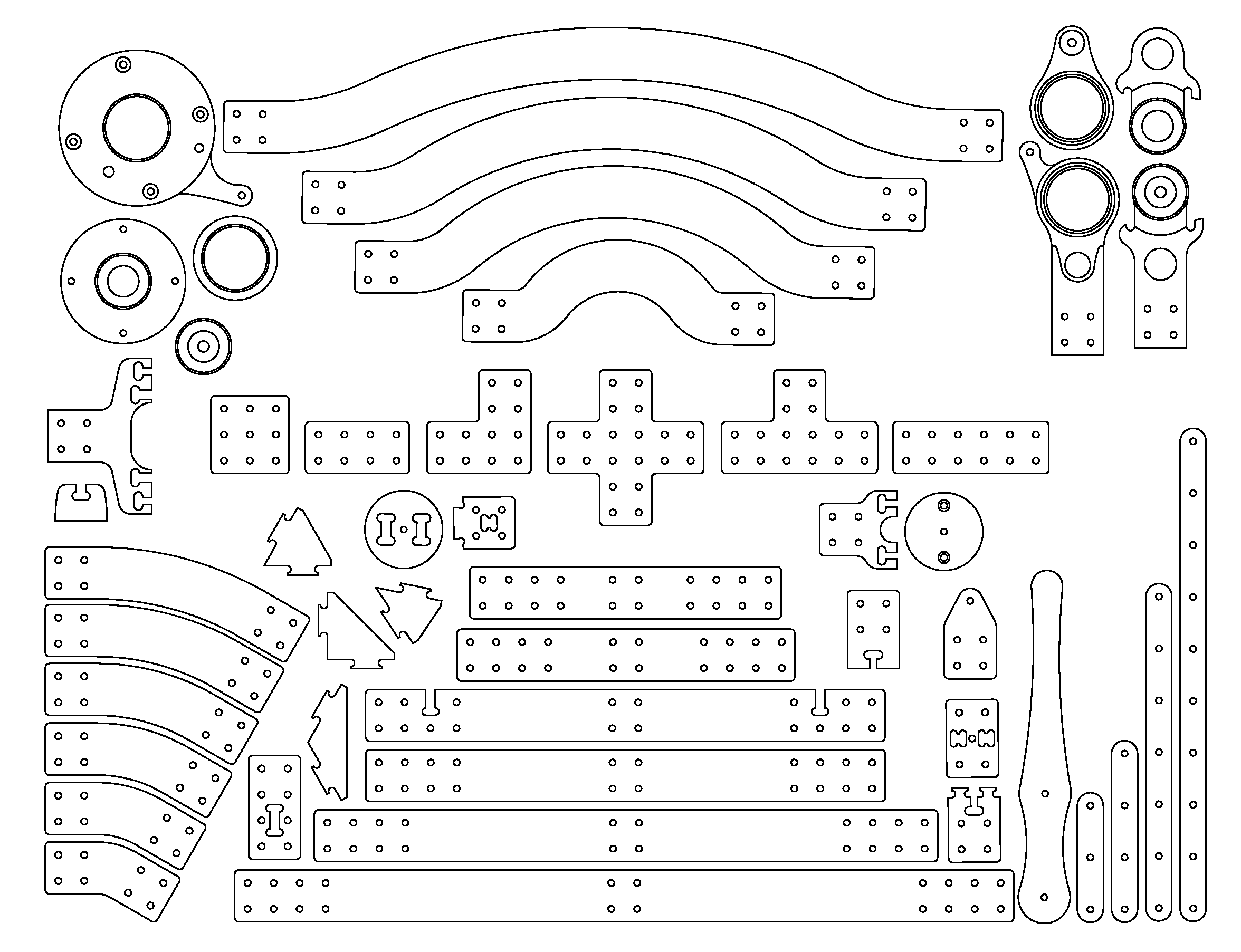
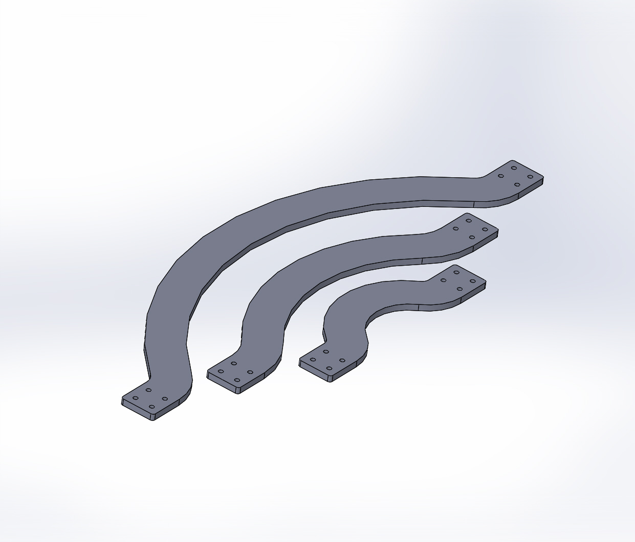
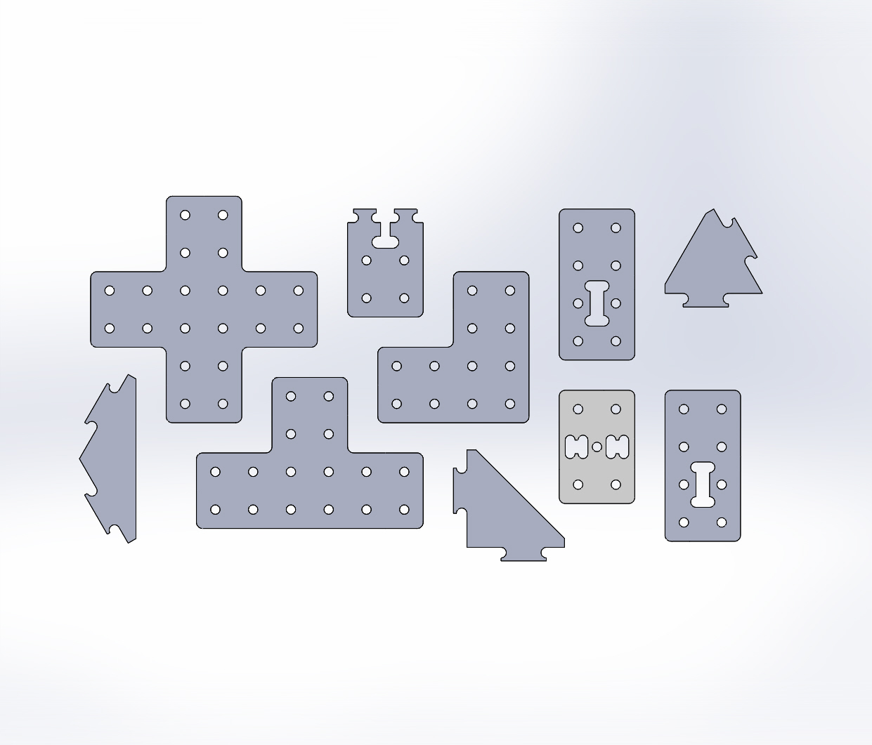
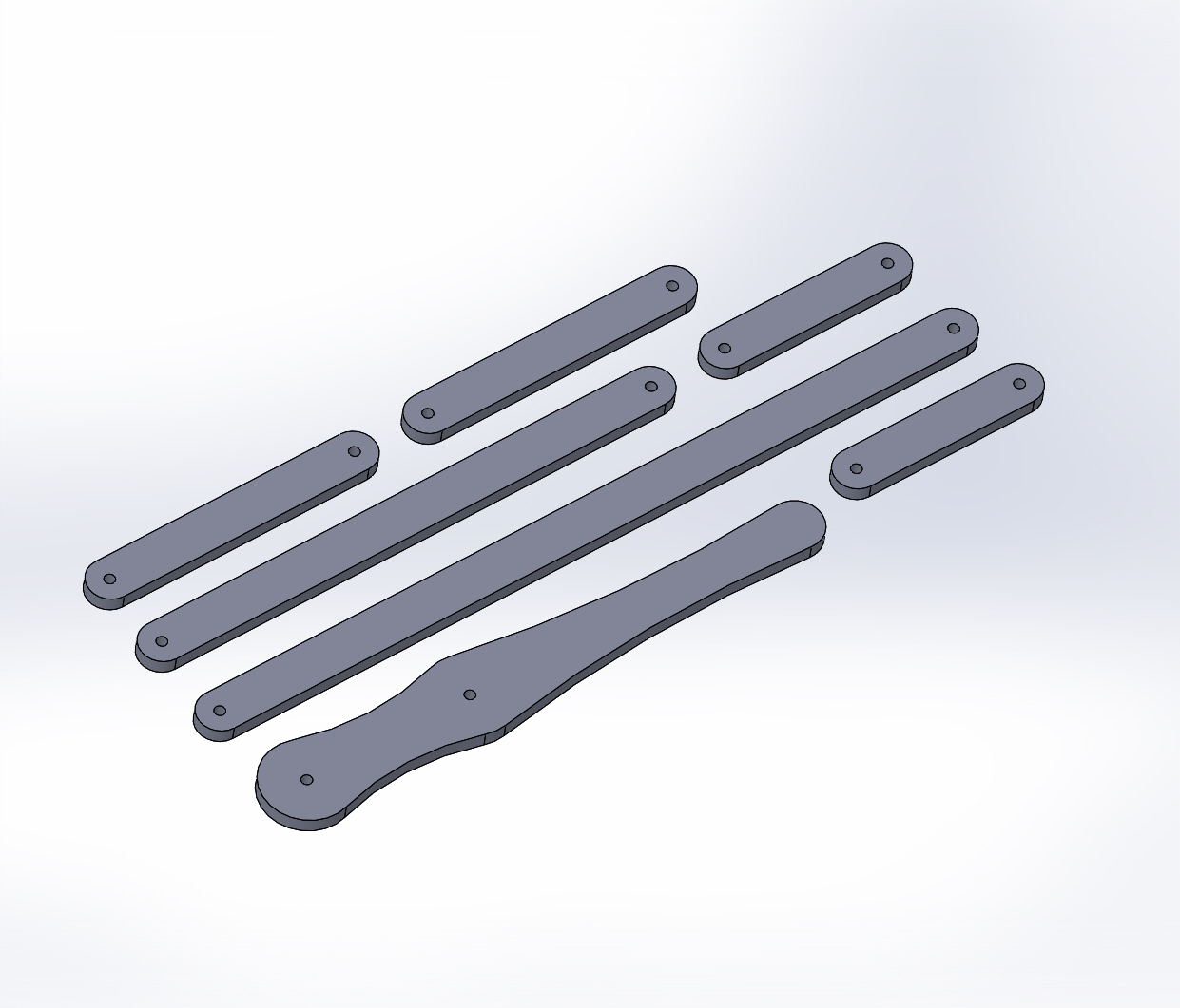
The special materials for the course include a rapid-prototyping kit of custom-cut wood parts and standard mechanical components to enable quickly building articulated and actuated structures without a minimum of fabrication. This is in keeping with the course focus on surprisingly animate behavior. Building new machines from scratch is laborious, so providing these materials is intended to enable rapid exploration of physical dynamics and form in conjunction with programmed behavior.
The individual component designs are also available for customization, so projects will have the options of making custom parts, subject to CAM experience and CNC router availability.
Contents
4.4.1. License and Repository

The text content and mechanical designs of the RCP Robot Kit by Garth Zeglin are licensed under a Creative Commons Attribution-ShareAlike 4.0 International License. Based on a work at https://courses.ideate.cmu.edu/16-375.
The original SolidWorks design files for the wooden components are available as a single zip file, or may be browsed file by file in the SolidWorks file tree.

4.4.3. Pneumatic Components
We are using a variety of pneumatic valves, manifolds, and components. Details to be added later.
4.4.4. Design Rules
The base components and subassemblies were designed with the following set of constraints, chosen for both general purpose utility and simplicity of fabrication. New parts for the kit should generally follow this rules. This list will continue to evolve.
- Material: 9mm Baltic Birch double-sided plywood. If a part requires more thickness, it can be 12mm Baltic Birch plywood. (Laser-cut parts will generally use thinner material).
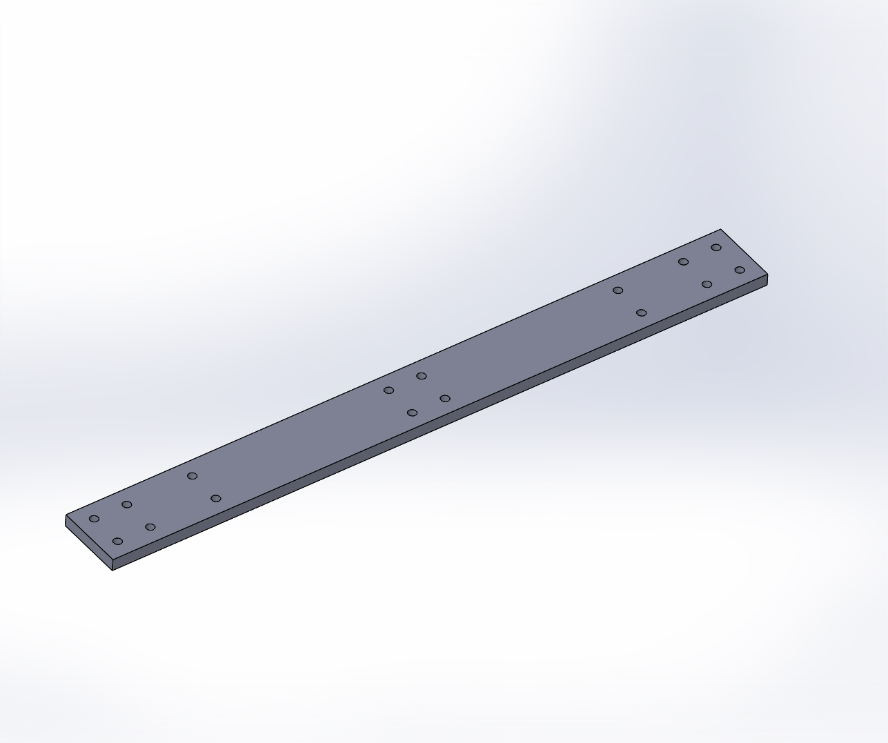
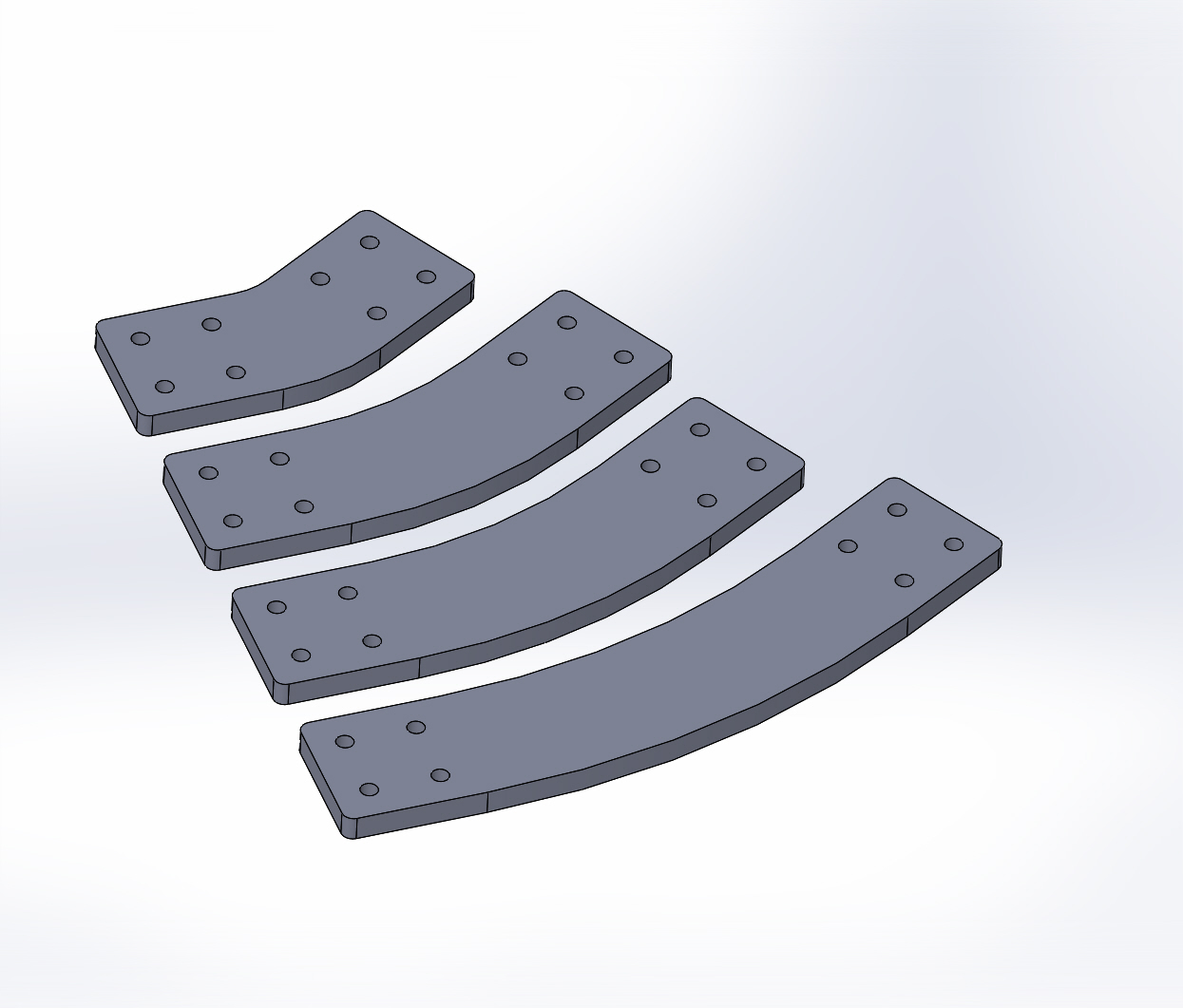
- Dimensional grid: part features are generally chosen on a 25mm grid. E.g, the basic straight connecting link is 50mm wide.
- Tightest curvature: 3.5 mm radius. Apart from drilled holes, the smallest required tool is a 0.250 inch end mill. (All the standard parts are programmed for just a 6 mm drill and 1/4 inch end mill.)
- Single-setup: all parts can be cut on a three-axis mill from a flat sheet in a single pass. I.e., one face can be contoured, holes and pockets can be cut through, but the back face must be planar since it will not be directly cut.
- Fasteners: M6 bolts and nuts. Specific components may require special cases, e.g., our pneumatic actuators use 6.35 mm (0.250 inch) bores and pins.
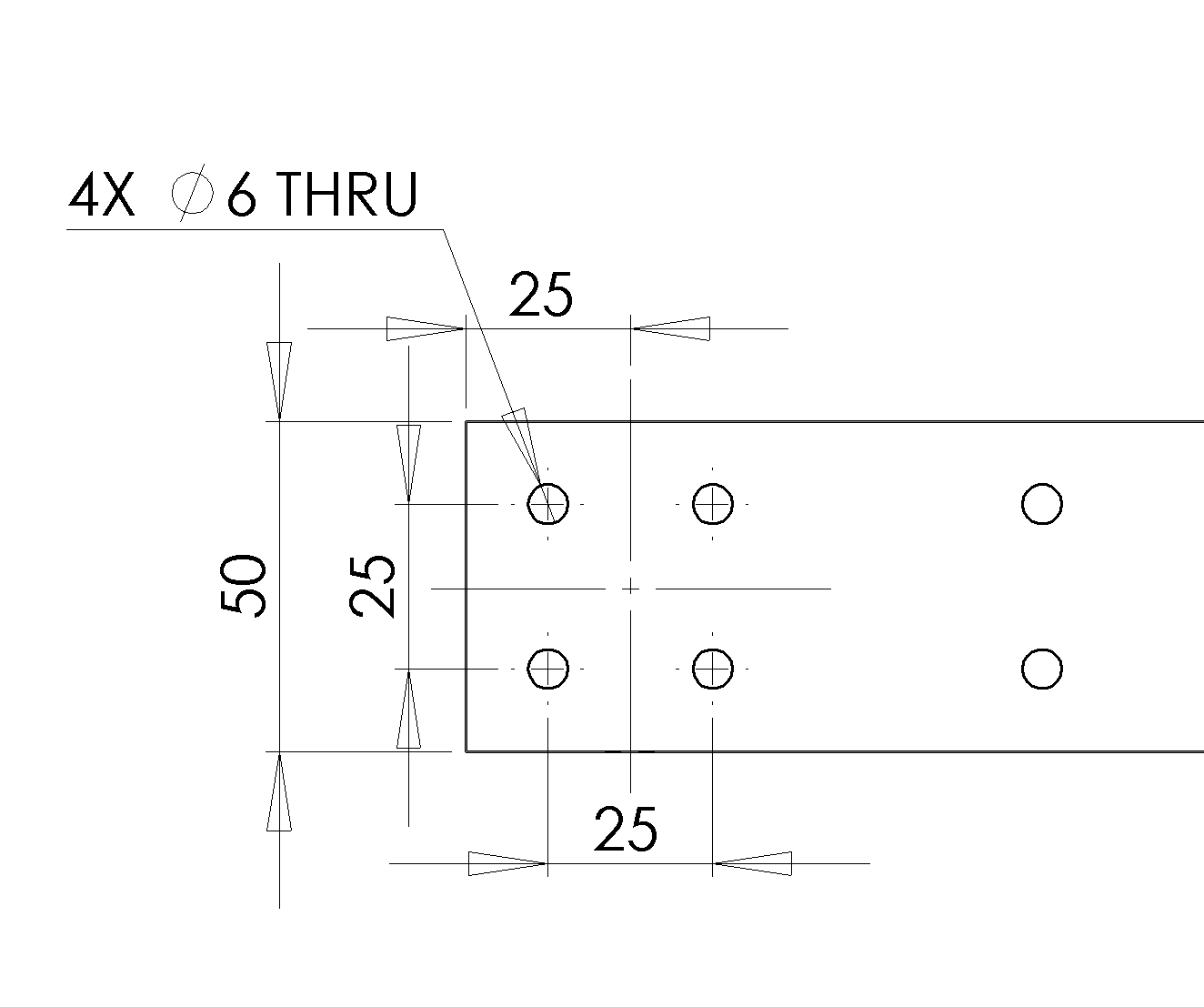
- Clearance holes: 6 mm drill. This is a close fit on an M6 screw.
- Bolt pattern: the standard interconnection pattern uses a 25 mm grid with four 6mm holes at the vertices of a square with 25 mm sides, centered in a 50mm square area.
- Shafts: 6mm shoulder screws.
- Shaft holes: 6mm drill. This is a free fit on a 6mm shoulder screw. (This may need adjustment.)
- Where parts glue together, provide 0.2 mm glue gap: increase holes in outer surfaces by 0.4 mm diameter, increase slot lengths and widths by 0.4 mm.
- Existing tabs are either 15 or 30 mm long. Existing slots are 9.4 mm wide and 15.4 mm or 30.4 long with the glue allowance. Inside corners are 3.5 mm radius. The preferred inside corner design uses a 180 degree arc, but the position varies depending on the purpose.
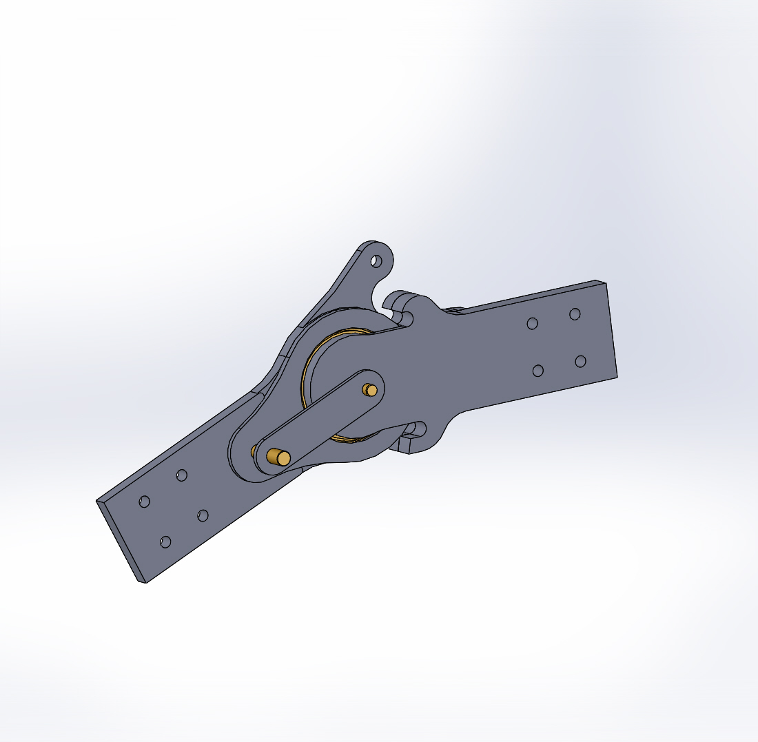
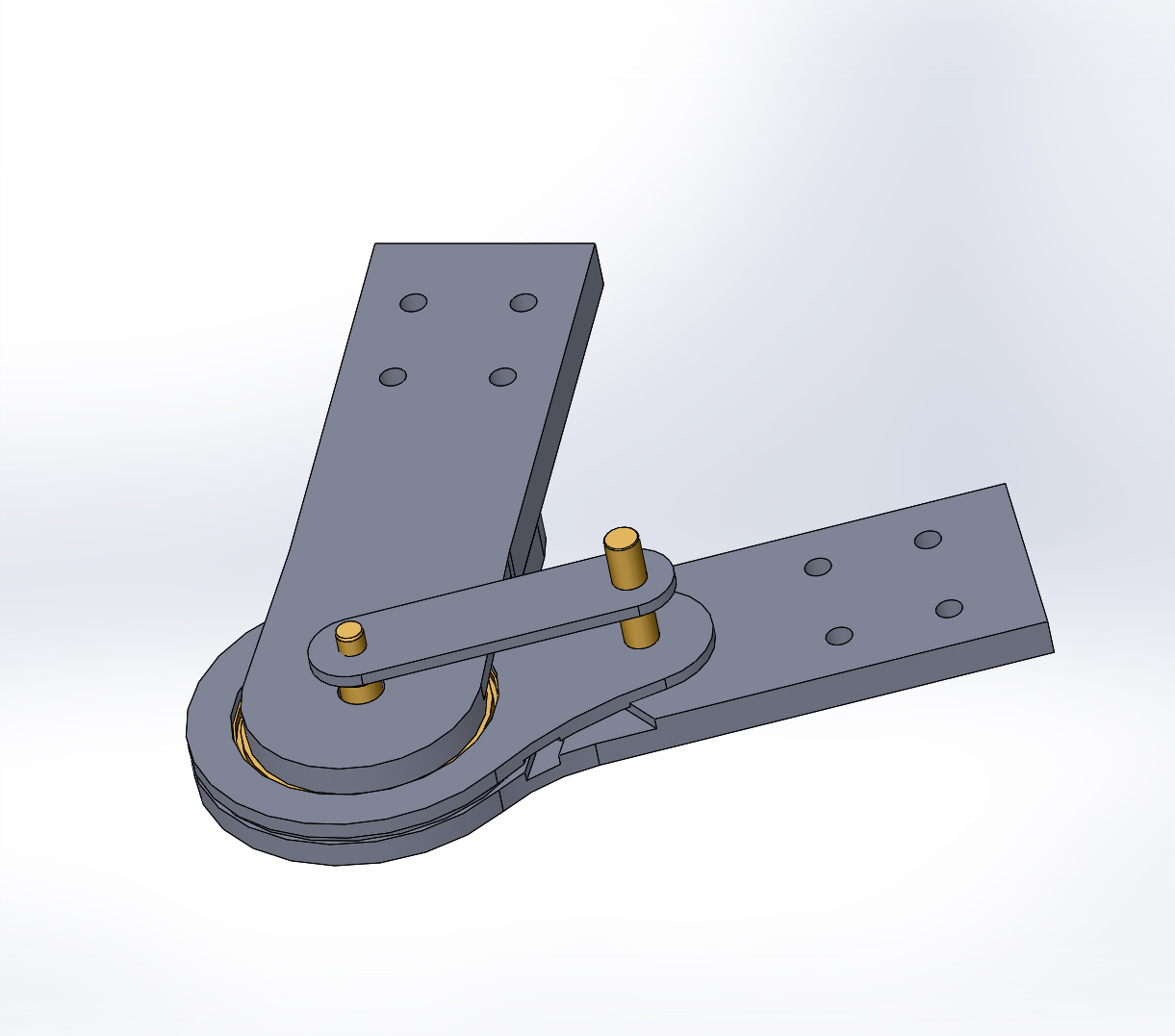
- Bearings: still in flux. Some components will use a 6mm shaft in a plain wooden hole, some may use a 6mm shaft in a bushing with 8mm OD, some may use an 8 mm shaft in a 8x22x7 mm skate ball bearing. The actuated knee designs use a 50x65x7 mm thin-section ball bearing.
- Dowel pins: 7.94 mm (5/16 in) grooved wooden pins, 38 mm (1.5 inch) long. (These are not a major feature.)
- Springs and cables: TBD.
- SolidWorks parts include Design Tables wherever possible with systematic parametric variations.
- Parts with right-angled corners have a 4 mm radius fillet to avoid sharp outside corners.