Exercise: Underactuated System Design
The main objective of this exercise is to explore kinematic principles through the design and simulation of a simple underactuated system. The emphasis is on designing a kinetic sculpture as an articulated structure of rigid bodies connected by joints. It will move under the combined influence of gravity, physics, and a single motor.
A fully actuated system is one in which every degree of freedom is controlled. For example, a typical industrial robot arm has six joints, each with an servomotor actuator with position control. Within the workspace the end effector has six degrees of freedom and the pose is fully controlled.
In contrast, an underactuated system has degrees of freedom which cannot be directly controlled. Our specific interest is in systems with more degrees of freedom than actuators, resulting in one or more passive freedoms. We utilize this kind of dynamics constantly, e.g. when pushing an object across a table using one fingertip, the point contact has only two freedoms but the object has three planar freedoms, and we use our experience of friction and dynamic control to stabilize the action.
In some sense, every robotic system is underactuated. At the core, the very notion of rigid body system is an abstraction which omits freedoms. But also in practice, robots which are mobile or which manipulate objects come into contact with a great many external freedoms which may transiently become part of the robot system. E.g. a mobile robot might need to open a door, or push around objects, or grasp a flexible or articulated object.
As a creative practice, passive freedoms add dynamic kinetic possibilities to a machine in a parsimonious way. Consider the use of clothing and hair in animation: the core expressive movements of the body are amplified through the motion of the attached soft materials.
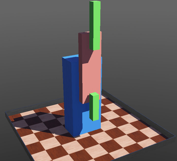
Screenshot of sample Webots model of 1-2 pendulum with a driven base joint and two passive distal joints. The robot is shown in the neutral pose.
Contents
Objectives
After this exercise, you should be able to:
Design a kinetic sculptural form using rigid bodies and joints.
Manipulate and extend a kinematic description of a rigid body system.
Attach actuators and sensors to simulated joints.
Reference Guides
Please review the following reference guides as needed:
Assigned video lecture clips.
Documentation on the sample project: Pendulum 1-2 Robot Model
Resources
The sample Webots project is a package of files and folders provided as a zip file pendulum-1-2.zip.
The course Piazza is a good place to collect and answer questions.
Creative Constraints
Only one actuated joint.
At least one passive joint.
All bodies are subject to contact, i.e., have bounding objects defined.
Parameters should be appropriate for a stable simulation. E.g., applying zero masses can cause the simulator to fail in particular poses, and that misses the point.
Creative Possibilities
You can choose whether gravity has a significant effect or not both by the orientation of joint axes and the locations of mass centers.
This exercise puts no particular constraints on the kinematic structure or overall form. E.g. the system could be one long kinematic chain like a triple-pendulum or whip, or it could have a tree-like structure of joints.
General Recommendations
Use hinge joints (pivots) to start; other joint types can come later (e.g. linear sliding joints).
Choose a convenient ‘reference pose’ in which all joints are at a neutral position. The work will be simpler if this is as axis-aligned as possible.
The Webots native units are meters. Shape objects can be scaled but it is simplest to design in meters.
Start with careful paper sketches, including a careful kinematic diagram with the joint axes and body coordinate systems.
Build and test a model incrementally. It is much easier to fix coordinate systems and parameter vectors in stages.
Use basic geometric forms to work out the kinematics, dynamics, and contact models. The visual shape and rendering properties can be detailed later if desired.
Parameters can be adjusted while the simulator is running. But I highly recommend you get in the habit of resetting the simulation state before saving any world changes in order to preserve the accuracy of the initial conditions.
Modeling the Kinematics and Dynamics
The following assumes you’ve already have a working Webots simulator installed with Python 3. A separate 3D modeling system is not required, although you may optionally create and import your own shape models using CAD tools.
Please download the Webots project zip file linked above and unpack it wherever convenient for you.
After unpacking, please locate the following contents:
pendulum-1-2/worlds/pendulum-1-2-sample.wbt: sample world file, opening it should launch the simulatorpendulum-1-2/controllers/pendulum_1_2/pendulum_1_2.py: Python script to control the simulated robot
I recommend you start by descending into the Robot object in the scene tree and comparing the nodes against the description in System Kinematics and the dimensioned drawing in CAD Drawings.
The simplest way to add a new link to the sample is to find the parent object and duplicate and modify the HingeJoint subtree found within the children list. The parent might be the Robot node to add a new joint to the base, the link1 Solid node to add a new distal link on link1, or either the link1A or link2B Solid nodes to deepen the structure further.
If the copied link shouldn’t share geometry, then the DEF entries for the new shape will need to be renamed and the boundingObject USE link updated.
The position sensor names within the copy will need to be set to sensible values so the controller can connect to them.
Actuation and Movement
A physical structure with rich dynamics may not need much motion programming, as even simple actuation processes might activate the structure by exciting the dynamics. The sample controller code just applies a periodic torque via the motor. This could be elaborated by introducing terms which couple the joint position signals to the torque, whether to drive the system toward stable equilibria or instability.
Deliverables
Please submit to Canvas:
A paragraph briefly describing your sculptural objectives and outcomes.
Short video clip (under one minute) of simulated behavior, submitted to Canvas either as a video file or a link to a third-party streaming service.
Zip file of your Webots project.
Further Study
Underactuated Robotics course taught by Russ Tedrake at MIT.