Two-Link Robot Model
The two-link robot model simulates a planar two-link robot with an actuator at each joint and a sensor at the end. The model is intended as a demonstration testbed for two-link kinematics.
The link geometry uses only cylinder primitives. The same geometry is referenced to use as bounding objects for collision and automatic calculation of physics parameters. The base object has a NULL Physics object so it does not move, simulating a rigid connection to the ground.
The end sensor is represented by a yellow cone. It is implemented as a DistanceSensor of limited range, pointing outward along the link axis from the end of the second link.
This model is demonstrated in the sensor-demo.wbt and controls-demo.wbt worlds.
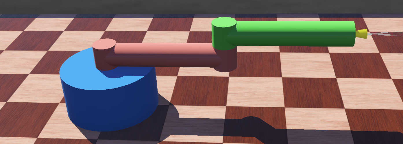
Screenshot of Webots model of fully-actuated two-link planar robot.
System Kinematics
The bodies are as follows:
name |
color |
notes |
|---|---|---|
base |
blue |
base object fixed to the ground |
link1 |
red |
proximal link, attaches to base at ‘shoulder’ |
link2 |
green |
the distal link, attaches to link1 at ‘elbow’ |
The joints are as follows:
name |
parent |
child |
notes |
|---|---|---|---|
joint1 |
base |
link1 |
the ‘shoulder’, includes motor1 |
joint2 |
link1 |
link2 |
the ‘elbow’, includes motor2 |
The axes are as follows:
name |
direction |
notes |
|---|---|---|
joint1 |
along Z |
located above the origin |
joint2 |
along Z |
located at the end of link1 |
The motors and sensors are named as follows:
name |
notes |
|---|---|
motor1 |
RotationalMotor on joint1 |
motor2 |
RotationalMotor on joint2 |
joint1 |
PositionSensor on joint1 |
joint2 |
PositionSensor on joint2 |
endRangeSensor |
DistanceSensor at end of link2 |
two-link.proto
The robot model has been encapsulated in a .proto file for easy reuse. The model includes user-accessible link length parameters to demonstrate procedural scaling.
  1#VRML_SIM R2023b utf8
  2# documentation url: https://courses.ideate.cmu.edu/16-375
  3# Planar two-link actuated arm for course exercises.  The graphics use only
  4# primitives for clarity of the source. The base has NULL physics so it will be
  5# fixed in place. The two link lengths are adjustable parameters to demonstrate
  6# using procedural elements in the prototype.  The link physics properties are
  7# specified using density so the dynamics will also scale, but the motor
  8# parameters are constant.  The end includes a distance sensor pointed along the
  9# axis.
 10# license: No copyright, 2020-2026 Garth Zeglin.  This file is explicitly placed in the public domain.
 11# template language: javascript
 12
 13PROTO two-link [
 14  field SFVec3f    translation  0 0 0
 15  field SFRotation rotation     0 1 0 0
 16  field SFFloat    link1Length  0.5
 17  field SFFloat    link2Length  0.5
 18  field SFString   controller   "two_link"
 19  field SFString   name         ""
 20  field SFString   customData   ""
 21]
 22{
 23  Robot {
 24    # connect properties to user-visible data fields
 25    translation IS translation
 26    rotation IS rotation
 27    controller IS controller
 28    name IS name
 29    customData IS customData
 30
 31    # calculate derived parameters
 32    %<
 33      let halfLink1Len = fields.link1Length.value / 2;
 34      let halfLink2Len = fields.link2Length.value / 2;
 35    >%
 36
 37    # define the kinematic tree
 38    children [
 39      # add a default radio receiver and transmitter
 40      Receiver {
 41      }
 42      Emitter {
 43      }
 44
 45      # the cylindrical base shape is wrapped in a Transform
 46      # to position it within the robot body coordinates
 47      DEF baseObject Transform {
 48        translation 0 0 0.1
 49        children [
 50          Shape {
 51            appearance PBRAppearance {
 52              baseColor 0.21529 0.543008 0.99855
 53              metalness 0
 54            }
 55            geometry Cylinder {
 56	      height 0.2
 57	      radius 0.2
 58            }
 59          }
 60        ]
 61      }
 62      # define the base pivot joint connecting the base
 63      # and the first link
 64      HingeJoint {
 65        jointParameters HingeJointParameters {
 66          axis 0 0 1
 67        }
 68        device [
 69          PositionSensor {
 70            name "joint1"
 71          }
 72          RotationalMotor {
 73            name "motor1"
 74            acceleration 2
 75            maxVelocity 3.14
 76	    # maxTorque 2
 77	    maxTorque 20
 78          }
 79        ]
 80        # start definition of the first link
 81        endPoint Solid {
 82          # place the shape origin halfway along the first link;
 83          # this vector is in body coordinates, X points along
 84          # the link in the neutral pose
 85          translation %<=halfLink1Len>% 0 0.25
 86          children [
 87            # define the 'elbow' pivot connecting the links
 88            HingeJoint {
 89              jointParameters HingeJointParameters {
 90                axis 0 0 1
 91                # place the elbow joint axis at the end of the first
 92                # link; position is relative to link1 origin
 93                anchor %<= halfLink1Len >% 0 0
 94                dampingConstant 0.1
 95              }
 96              device [
 97                PositionSensor {
 98                  name "joint2"
 99                }
100                RotationalMotor {
101                name "motor2"
102                acceleration 2
103                maxVelocity 6.28
104                # maxTorque 1.5
105		maxTorque 15
106                }
107              ]
108              # define the second link
109              endPoint Solid {
110                # place the link2 origin halfway along the second link
111                translation %<= halfLink1Len+halfLink2Len>% 0 0.1
112                children [
113                  # the cylindrical link shape is wrapped in a Transform
114                  # to position it within the link2 coordinates
115                  DEF link2Shape Transform {
116                    # the Cylinder shape coordinates use Z as the
117                    # long axis; this 90 deg rotation around Y
118                    # places the lengthwise Z axis along the link.
119                    rotation 0 1 0 1.5708
120                    children [
121                      Shape {
122                        appearance DEF greenAppearance PBRAppearance {
123                          baseColor 0.413001 1 0.33489
124                          metalness 0
125                        }
126                        geometry Cylinder {
127                          height IS link2Length
128                          radius 0.05
129                        }
130                      }
131                   ]
132                 } # end link2 Shape
133	     	 # add a visual hub to the base of link2, not part of the bounding object
134	     	 Transform {
135             	    rotation 0 1 0 0
136             	    translation %<= -halfLink2Len>% 0 0
137  	     	 	children [
138	     	 	  Shape {
139             	        appearance USE greenAppearance
140             	        geometry Cylinder {
141	     	 	      height 0.1
142	     	 	      radius 0.05
143	     	 	    }
144	     	 	  }
145	     	 	]
146             	 } # end Transform around link2 base hub
147		 # define a DistanceSensor attached to the second link Solid node
148                 DistanceSensor {
149                   translation %<= halfLink2Len>% 0 0
150                   name "endRangeSensor"
151
152		   # the sensor lookup table implicitly defines the maximum range and the units, each
153		   # entry is [distance, value, noise]
154                   lookupTable [
155                     0 0 0
156                     0.9 0.9 0    # 0.9 meters reads as 0.9 meters
157                   ]
158		   resolution 0.001 # assume millimeter resolution
159                   numberOfRays 5
160                   aperture 0.1
161                   children [
162                     Transform {
163                       rotation 0 -1 0 1.5708
164                       children [
165                         Shape {
166                           appearance PBRAppearance {
167                             baseColor 1 0.99028 0.0584421
168                             roughness 0.5
169                             metalness 0.5
170                             emissiveColor 1 0.99028 0.0584421
171                             emissiveIntensity 0.2
172                           }
173                           geometry Cone {
174                             bottomRadius 0.02
175                             height 0.1
176                           }
177                         }
178                       ]
179                     }
180                   ]
181                 } # end DistanceSensor
182                ] # end link2 Solid children
183                # top-level properties of link2
184                name "link2"
185                boundingObject USE link2Shape
186                physics Physics {
187                  # Assume the link is a thin-walled aluminum tube with 50 mm
188		  # radius and 2 mm wall thickness.  Aluminum has a density of
189		  # 2700 kg/m^3, but this will be scaled by the ratio of the
190		  # tube cross-section to the solid cylinder cross-section
191		  # assumed by the simulator.  Note that the moment of inertia
192		  # around the long axis will be underestimated.
193		  # density = 2700 * (R_outer**2 - R_inner**2) / R_outer**2
194                  density 211.7
195                  mass -1
196                }
197              }
198            }
199            # finish the definition of link1 with a shape
200            # node in the 'children' list
201            DEF link1Shape Transform {
202              rotation 0 1 0 1.5708
203              children [
204                Shape {
205                  appearance DEF redAppearance PBRAppearance {
206                     baseColor 00.990494 0.516915 0.468254
207                     metalness 0
208                  }
209                  geometry Cylinder {
210                    height IS link1Length
211                    radius 0.05
212                  }
213                }
214               ]
215             }
216	     # add a visual hub to the base of link1, not part of the bounding object
217	     Transform {
218                rotation 1 0 0 0
219                translation %<= -halfLink1Len>% 0 0
220  		children [
221		  Shape {
222                    appearance USE redAppearance
223                    geometry Cylinder {
224		      height 0.1
225		      radius 0.05
226		    }
227		  }
228		]
229             } # end Transform around link1 base hub
230	     # add a visual hub to the end of link1, not part of the bounding object
231	     Transform {
232                rotation 1 0 0 0
233                translation %<= halfLink1Len>% 0 0
234  		children [
235		  Shape {
236                    appearance USE redAppearance
237                    geometry Cylinder {
238		      height 0.1
239		      radius 0.05
240		    }
241		  }
242		]
243             } # end Transform around link1 end hub
244          ] # close the children list of the link1 node
245          # top-level properties of link1
246          name "link1"
247          boundingObject USE link1Shape
248          physics Physics {
249	    # See notes for link2 density; this assumes the same geometry.
250            density 211.7
251            mass -1
252          }
253        }
254      }
255    ] # close the children list of the base node
256    # define top-level properties of the base
257    boundingObject USE baseObject
258
259    # the base of the robot itself has NULL physics to simulate being fixed to the ground
260    # physics Physics { density -1 mass 10  }
261
262  } # close the Robot definition
263}
Sample Control Code
 1# two_link.py
 2#
 3# Sample Webots controller file for driving the two-link arm
 4# with two driven joints.  This example simulates a passive
 5# distal link by applying zero torque, then moves the
 6# base joint in a periodic excitation.
 7
 8# No copyright, 2020-2021, Garth Zeglin.  This file is
 9# explicitly placed in the public domain.
10
11print("loading two_link.py...")
12
13# Import the Webots simulator API.
14from controller import Robot
15
16# Define the time step in milliseconds between controller updates.
17EVENT_LOOP_DT = 200
18
19# Request a proxy object representing the robot to control.
20robot = Robot()
21robot_name = robot.getName()
22print("%s: controller connected." % (robot_name))
23
24# Fetch handle for the 'base' and 'elbow' joint motors.
25j1 = robot.getDevice('motor1')
26j2 = robot.getDevice('motor2')
27
28# Configure the motor for velocity control by setting
29# the position targets to infinity.
30j1.setPosition(float('inf'))
31
32# Start out with a 3 radian/second target rotational
33# velocity (roughly 180 deg/sec).
34j1.setVelocity(3)
35
36# Configure the second motor to freewheel.  Please note
37# this does not turn off the hinge friction.  For reference see:
38#  https://cyberbotics.com/doc/reference/motor
39#  https://cyberbotics.com/doc/reference/rotationalmotor
40j2.setTorque(0.0)
41
42# Run loop to execute a periodic script until the simulation quits.
43# If the controller returns -1, the simulator is quitting.
44while robot.step(EVENT_LOOP_DT) != -1:
45    # Read simulator clock time.
46    t = robot.getTime()
47
48    # Change the target velocity in a cycle with a two-second period.
49    if int(t) % 2 == 0:
50        j1.setVelocity(0)
51    else:
52        j1.setVelocity(3)
53