A central thesis of Human Machine Virtuosity is that human skill wielding a physical tool can be deeply expressive in a way that is complementary to the precision and scalability of digital design tools. This is a middle path between pure traditional craft and industrial manufacturing, which uses mostly standardized processes. The shared result of this project will constitute a unique design to fabrication toolkit which explores this hypothesis.
Given the current quarantine constraints, we are imagining that collaborations might revolve around a common conceptual direction, perhaps some shared software tools, but individual approaches to physical rendering. This may shift the emphasis from the application of digital fabrication tools to digital design tools that inform a manual fabrication process.
The key objective is the development and documentation of a workflow which incorporates appropriate elements of both digital design and expressive human skill and intuition. The production of sample artifacts is the means to demonstrate the workflow. The success of the projects will be gauged along two trajectories:
- The system designed: The project creates an enjoyable and robust design experience, encouraging sustained practice and interaction.
- The work produced: The project results in the making of compelling and novel design artifacts which reflect the hybrid explorations.
Schedule
- Wed Mar 18: new topic brainstorming, team formation
- Wed Mar 25: formal project release
- Mon Mar 30: project plan due
- Mon Apr 13: prototype workflow demonstration
- Mon Apr 20: sample artifact reviews
- Wed Apr 29: final presentation and critique
Deliverables
- project plan blog post
- A written description of your project detailing the project context, motivation, scope, and implementation (250 – 500 words).
- Workflow diagram identifying inputs, transformations, and outputs
- Identification of collaborative roles for shared results.
- Identification of individual fabrication methods.
- Identification of critical physical resources.
- Documentation of any preliminary prototypes.
- weekly prototypes (TBD on a per-project basis)
- a final report delivered as a post on the course blog including
- discussion of the system objectives
- a description of the design process in use
- video clip documenting the design process
- photos documenting the fabrication process
- documentation of the final artifacts
If you have not yet tried out the software, please consult the Computing Services page on Zoom.
Zoom Invitation
Garth Zeglin is inviting you to a scheduled Zoom meeting.
Topic: 16-455/48-530 Human-Machine Virtuosity
Time: This is a recurring meeting – Meet anytime
Join Zoom Meeting
https://cmu.zoom.us/j/760180996
Meeting ID: 760 180 996
One tap mobile
+19292056099,,760180996# US (New York)
+13126266799,,760180996# US (Chicago)
Dial by your location
+1 929 205 6099 US (New York)
+1 312 626 6799 US (Chicago)
+1 470 250 9358 US (Atlanta)
+1 646 518 9805 US (New York)
+1 786 635 1003 US (Miami)
+1 602 753 0140 US (Phoenix)
+1 651 372 8299 US
+1 669 219 2599 US (San Jose)
+1 669 900 6833 US (San Jose)
+1 720 928 9299 US (Denver)
+1 971 247 1195 US (Portland)
+1 213 338 8477 US (Los Angeles)
+1 253 215 8782 US
+1 301 715 8592 US
+1 346 248 7799 US (Houston)
Meeting ID: 760 180 996
Find your local number: https://cmu.zoom.us/u/avUBeAwH7
Join by SIP
760180996@zoomcrc.com
Join by H.323
162.255.37.11 (US West)
162.255.36.11 (US East)
221.122.88.195 (China)
115.114.131.7 (India Mumbai)
115.114.115.7 (India Hyderabad)
213.19.144.110 (EMEA)
103.122.166.55 (Australia)
209.9.211.110 (Hong Kong)
64.211.144.160 (Brazil)
69.174.57.160 (Canada)
207.226.132.110 (Japan)
Meeting ID: 760 180 996
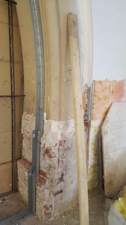
- clear identification of the site within the museum, including photographs and annotated drawings
- statement of the concept for the design and fabrication process
- sketches of potential fabricated results
- identification of the installation or mounting considerations
- identification of any special materials
- if feasible, any physical prototype
- if relevant, comment on the potential for a museum reimplementation of the process
The key objective is the development and documentation of a workflow which incorporates appropriate elements of both digital design and expressive human skill and intuition. The production of sample artifacts is the means to demonstrate the workflow. The success of the projects will be gauged along two trajectories:
- The system designed: The project creates an enjoyable and robust design experience, encouraging sustained practice and interaction.
- The work produced: The project results in the making of compelling and novel design artifacts which reflect the hybrid explorations.
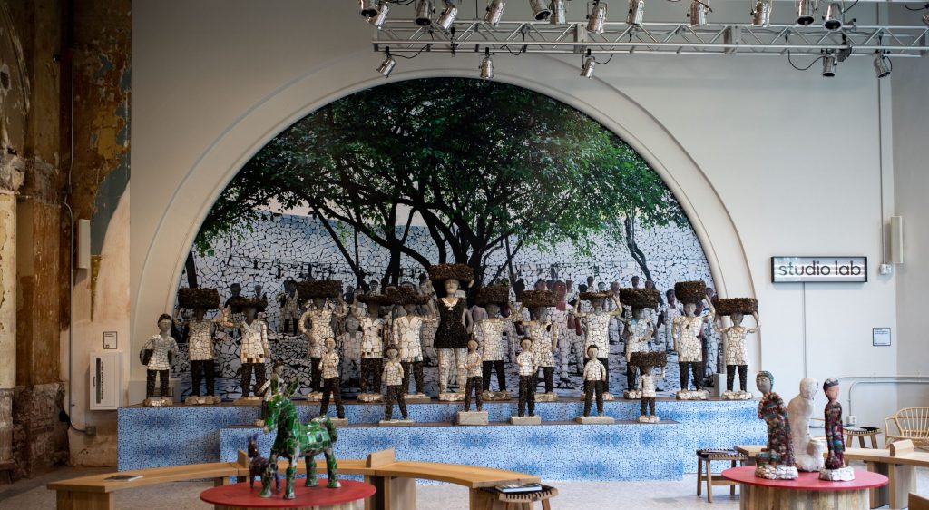
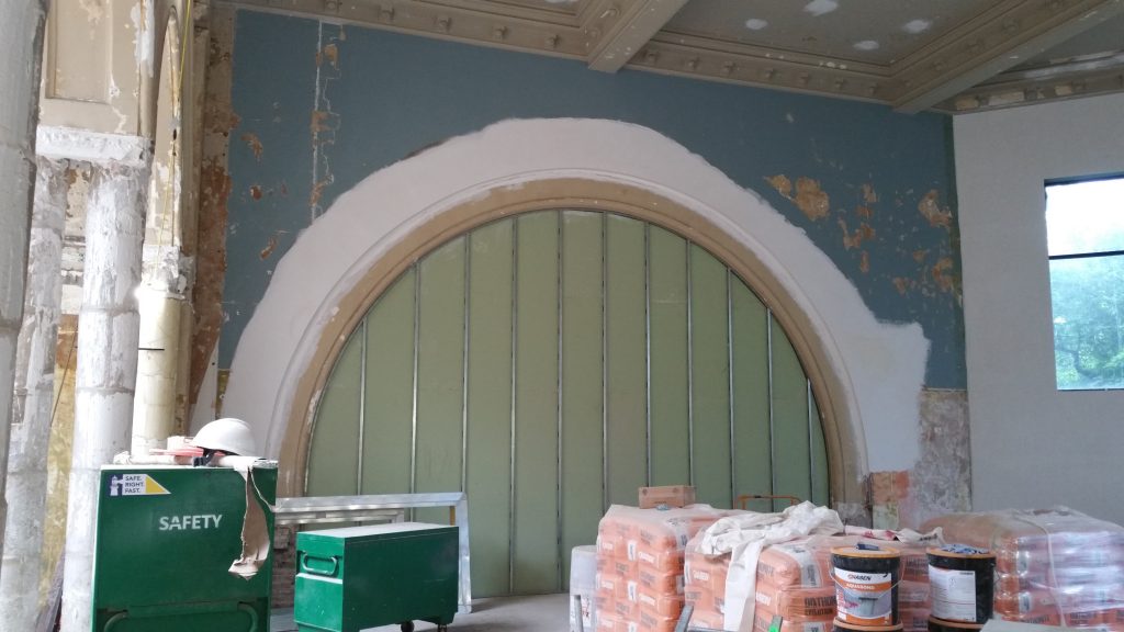
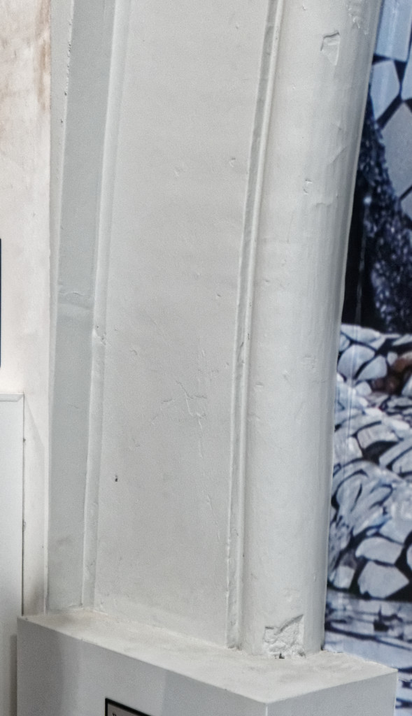
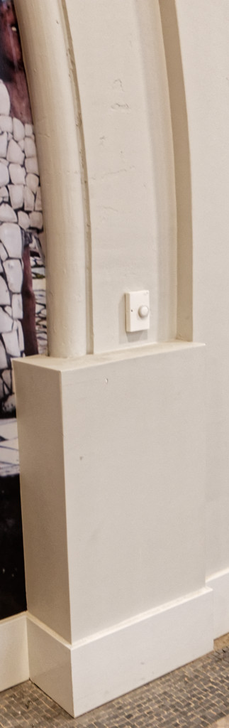
The museum is quite interested in at least one project continuing to work with the studiolab arch. This iteration could expand the scope of the site, e.g. to not only work with the flat face but also the adjoining wall and intervening ledge.
A secondary objective is directing at least one project toward means and materials which could be further developed by museum staff into an exhibit.
Schedule
- Wed Feb 26: project release, team formation
- Wed Mar 4: project pitch to museum staff (on campus)
- week of April 6: first in-situ test
- week of April 27: final installation and event
Deliverables
- pitch presentation
- weekly prototypes (TBD on a per-project basis)
- a final report delivered as a post on the course blog including
- discussion of the system objectives
- a description of the design process in use
- video clip documenting the design process
- photos documenting the fabrication process
- multiple plaster artifacts fabricated at scale to fit the site
Site Context
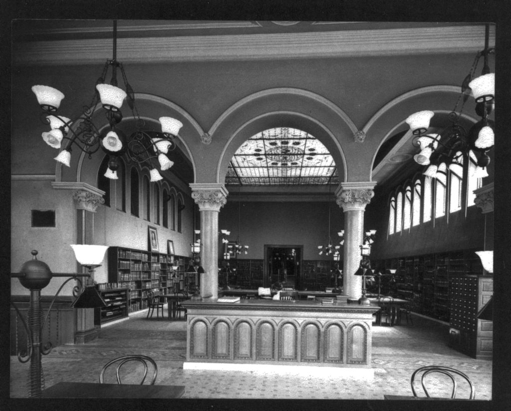
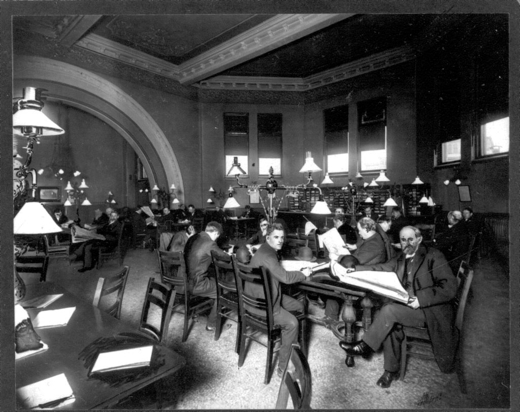
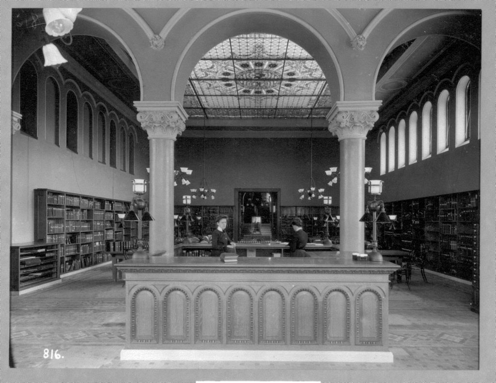
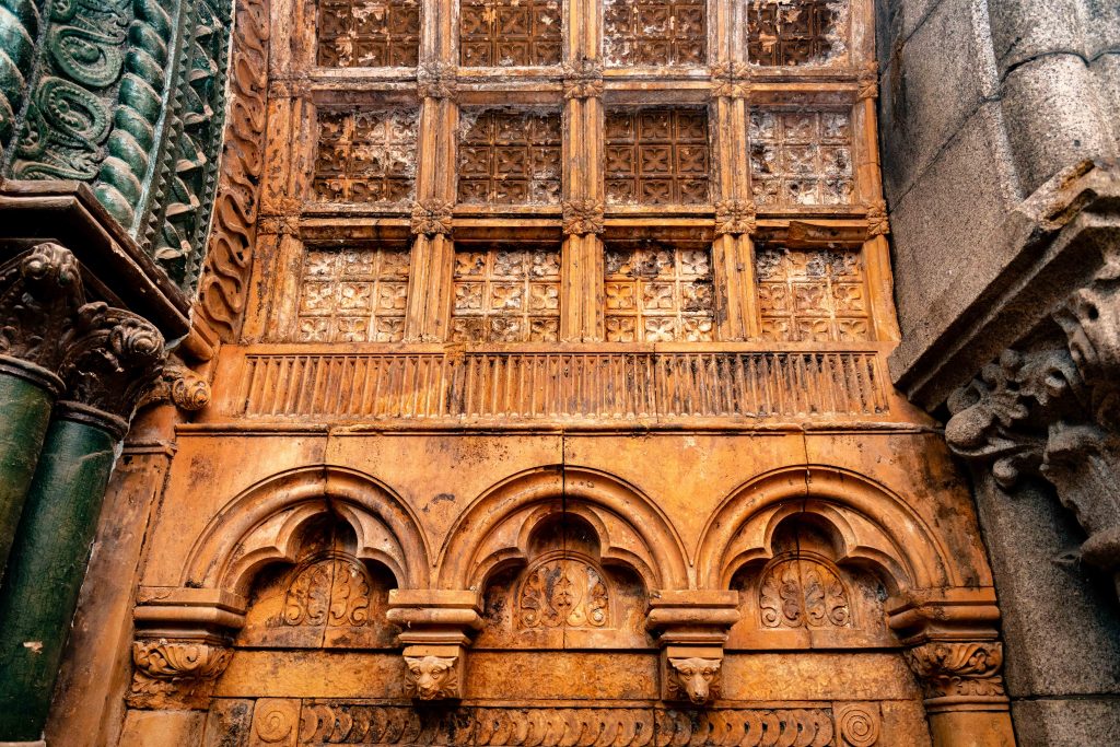
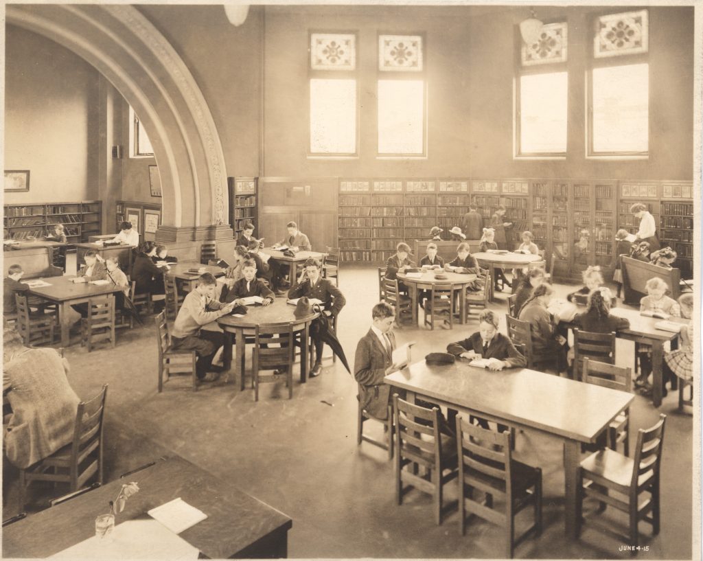
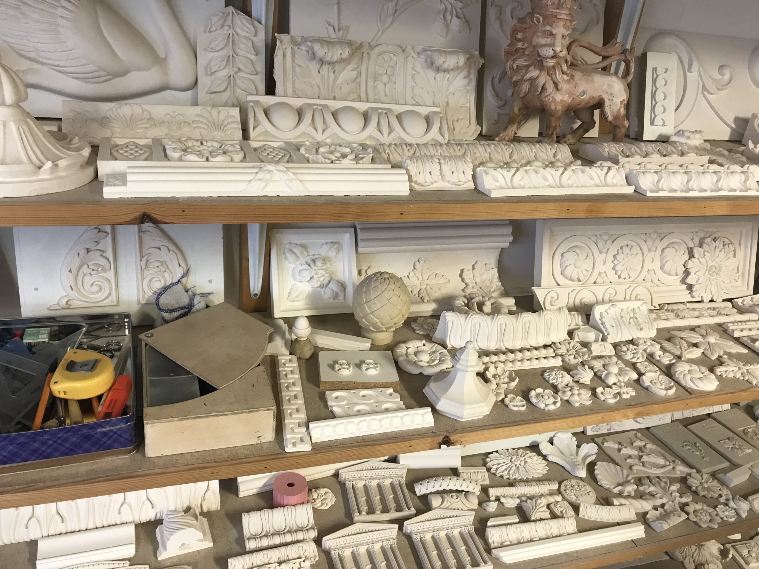
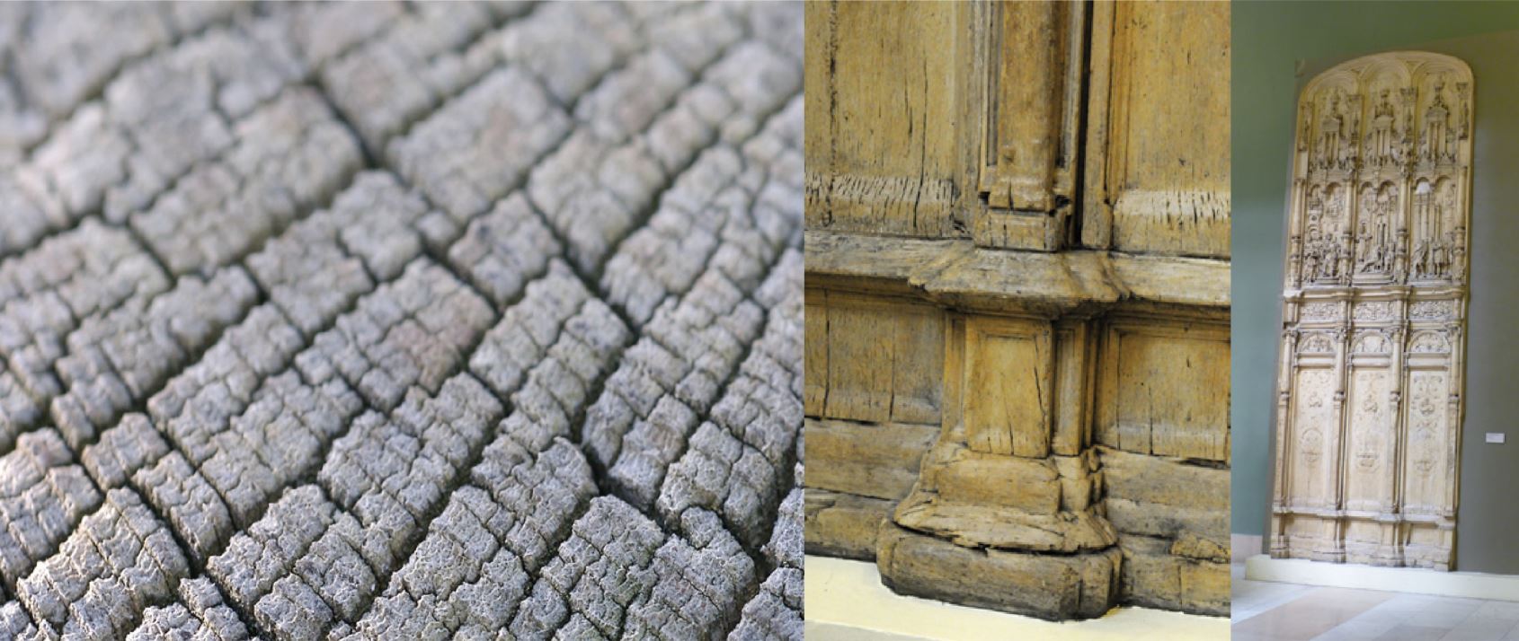
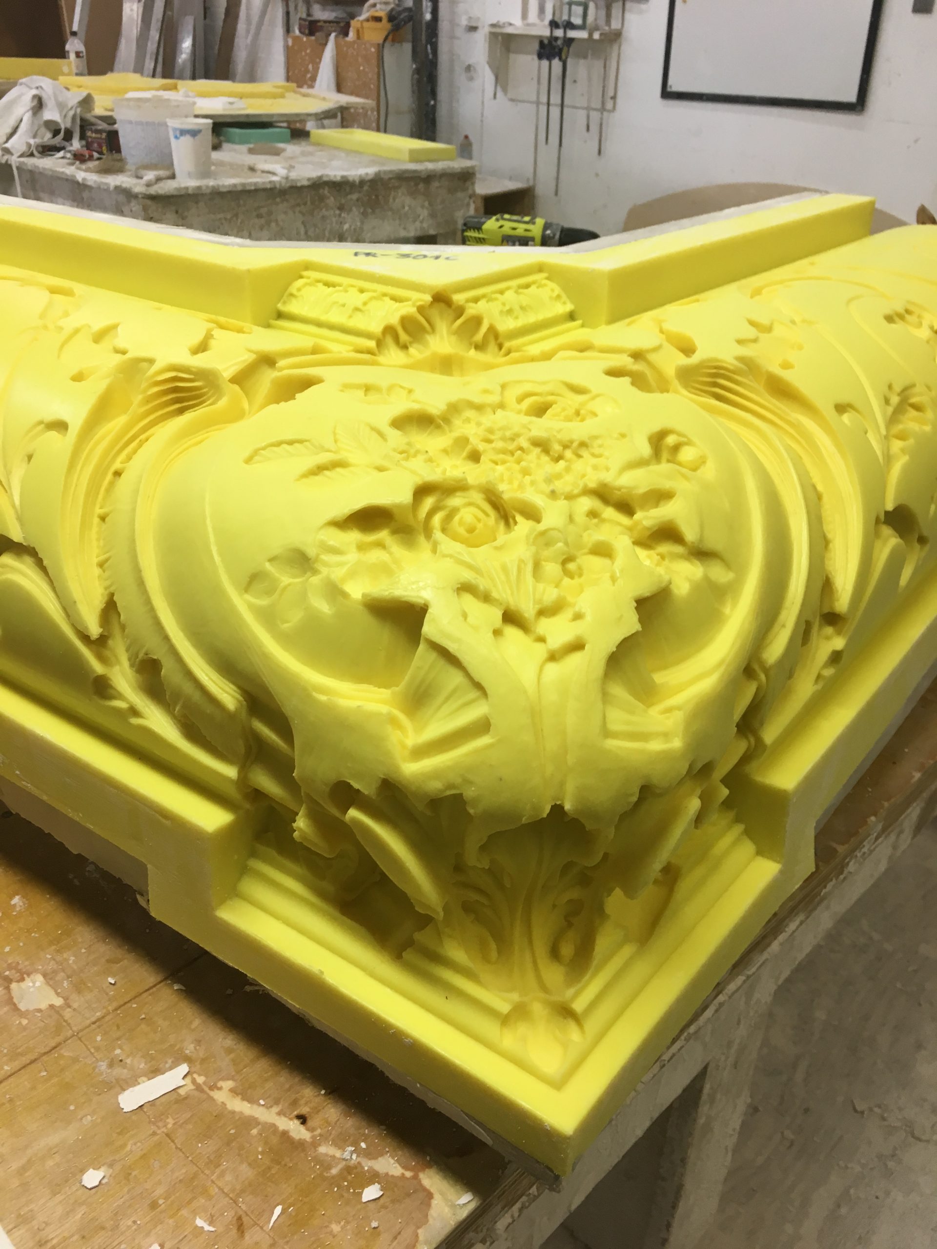
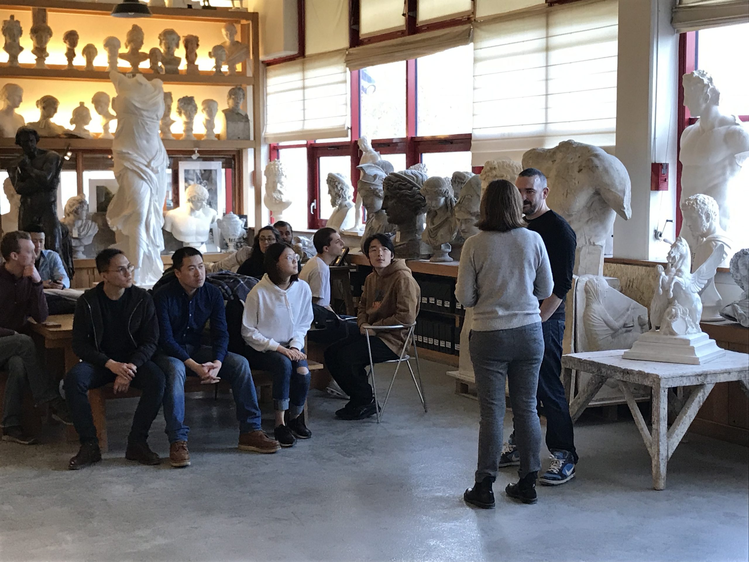
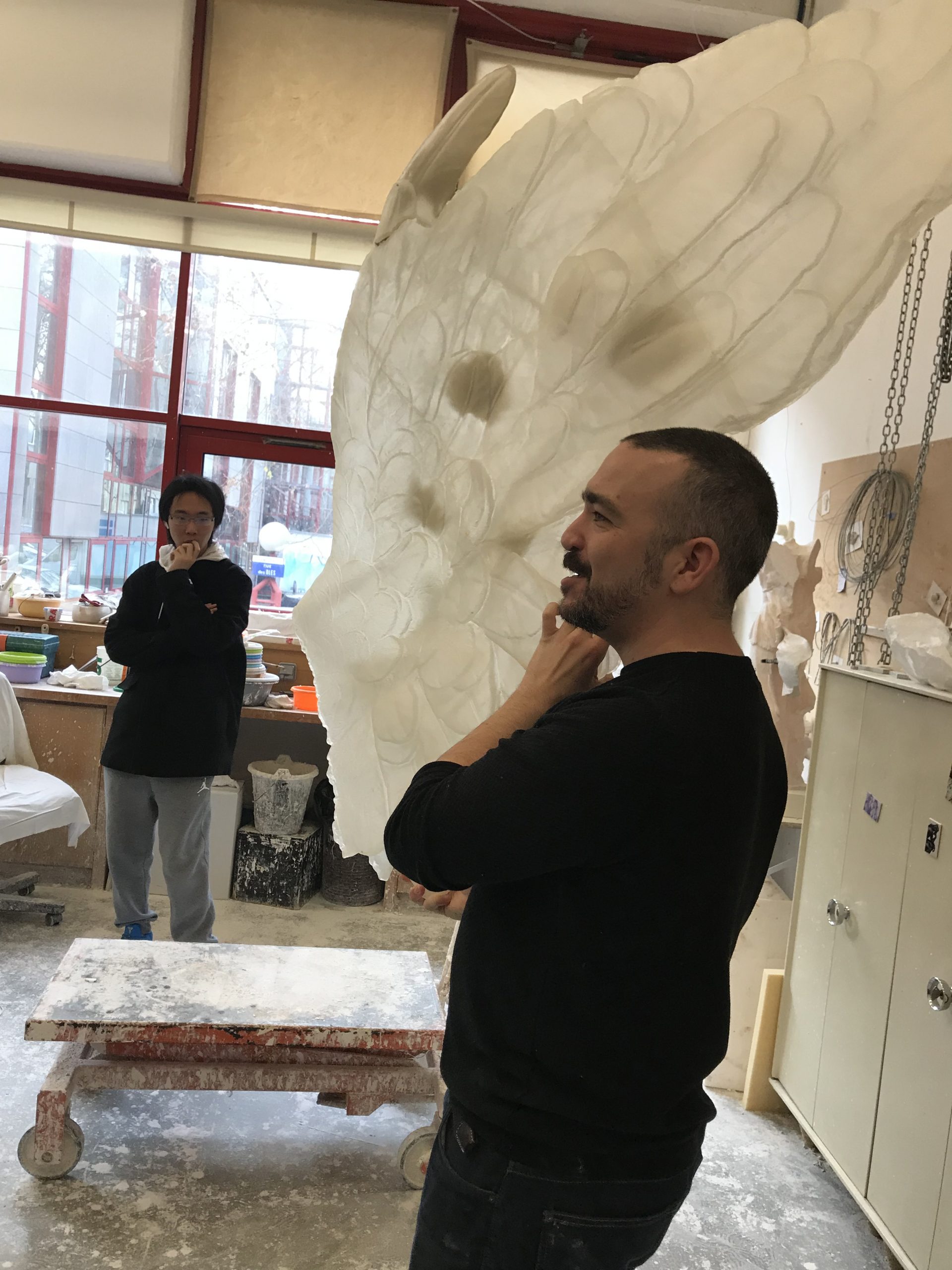
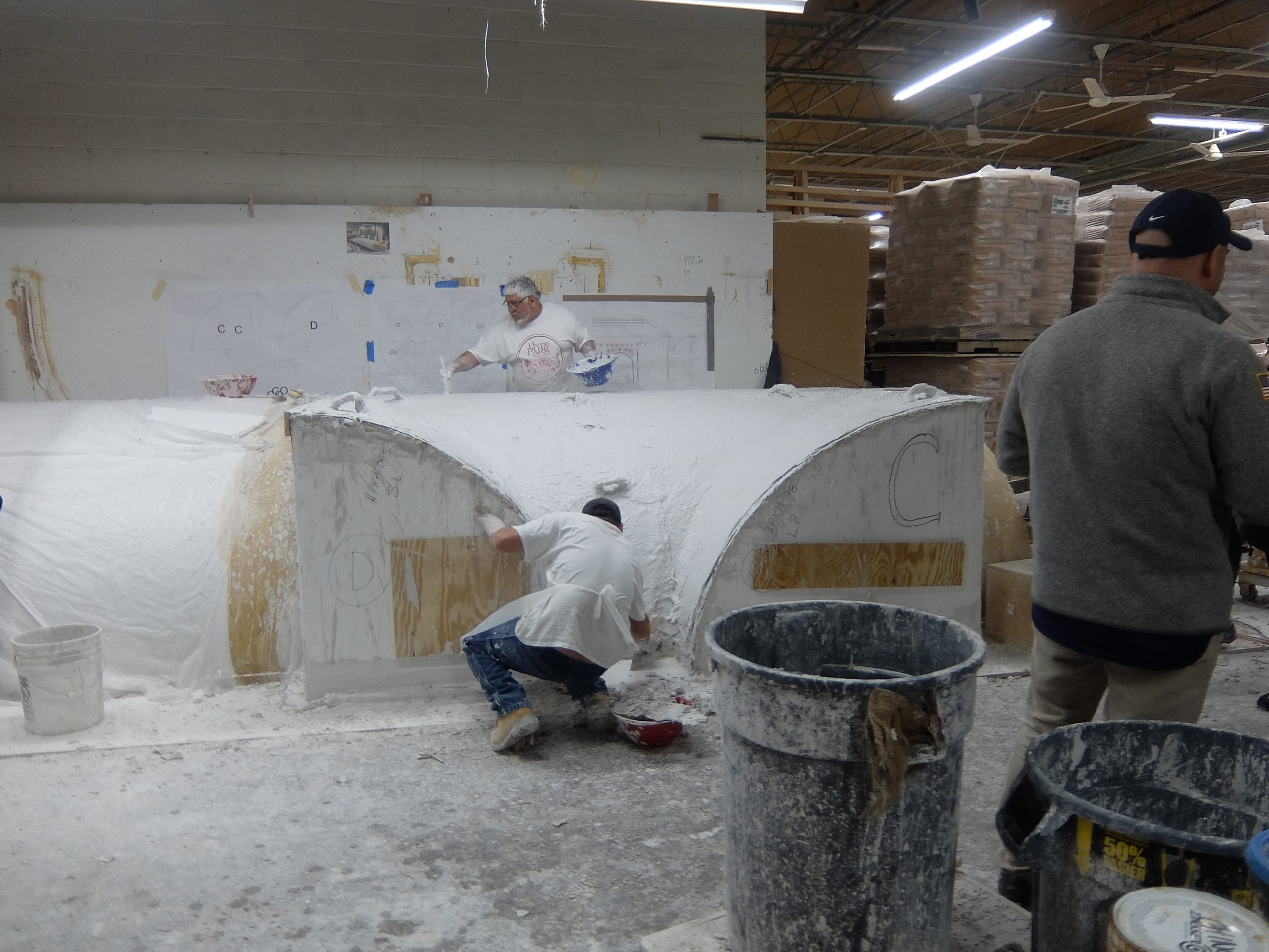
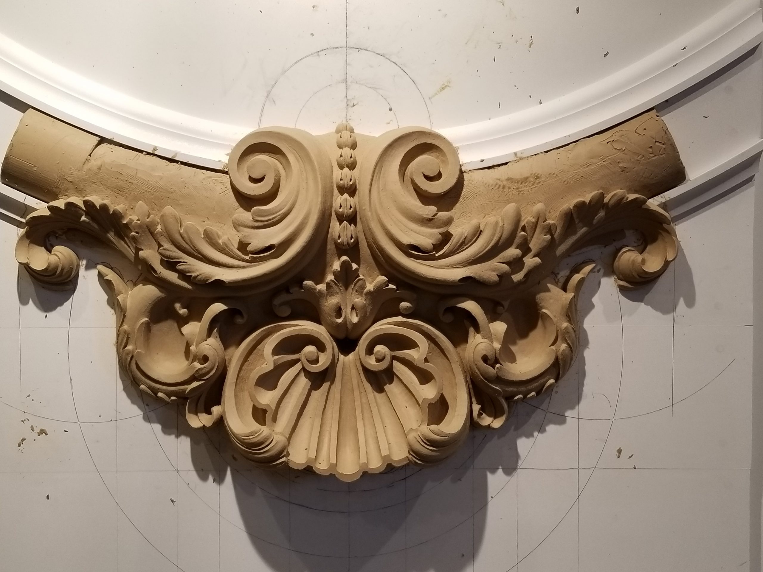
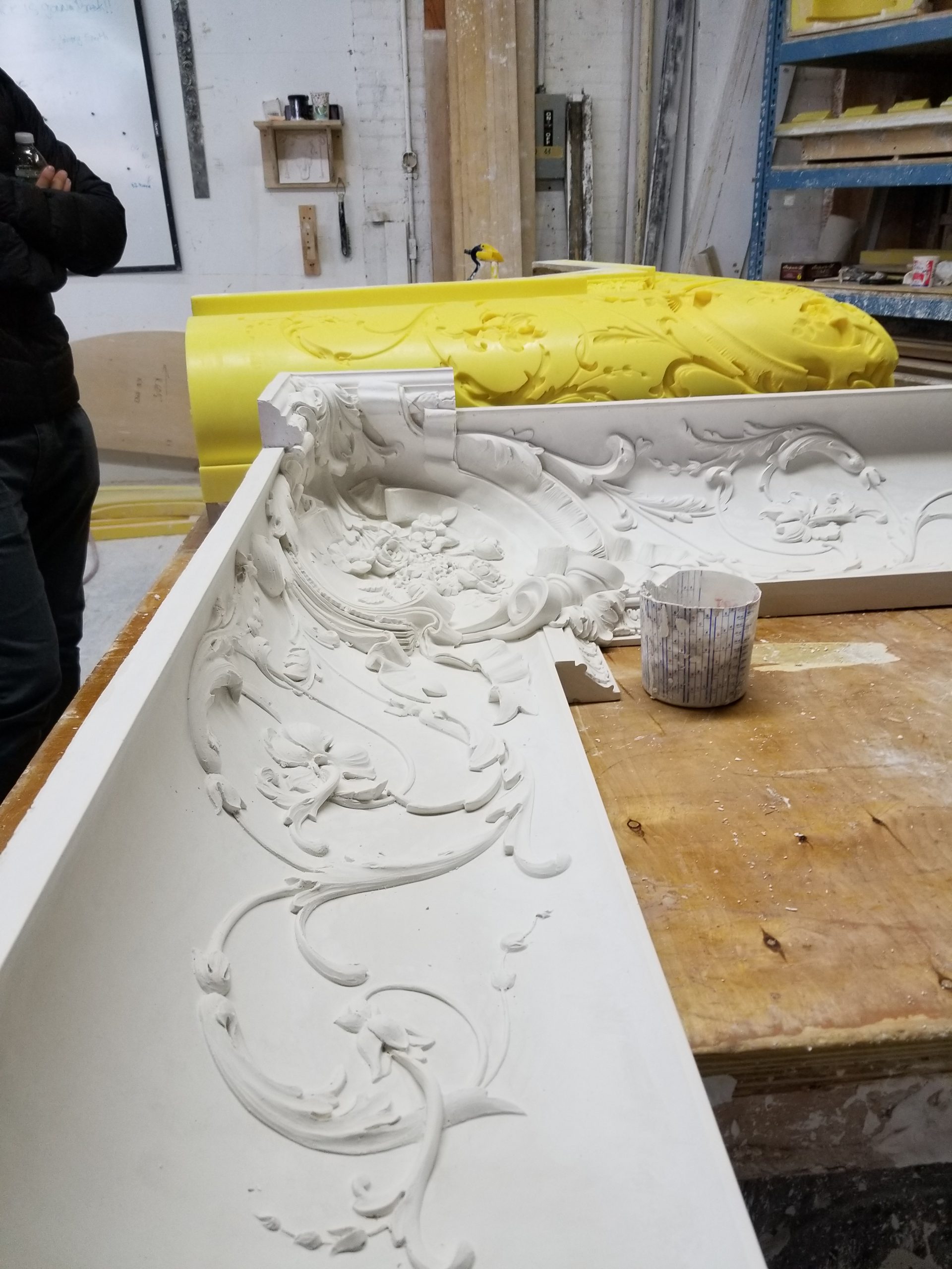
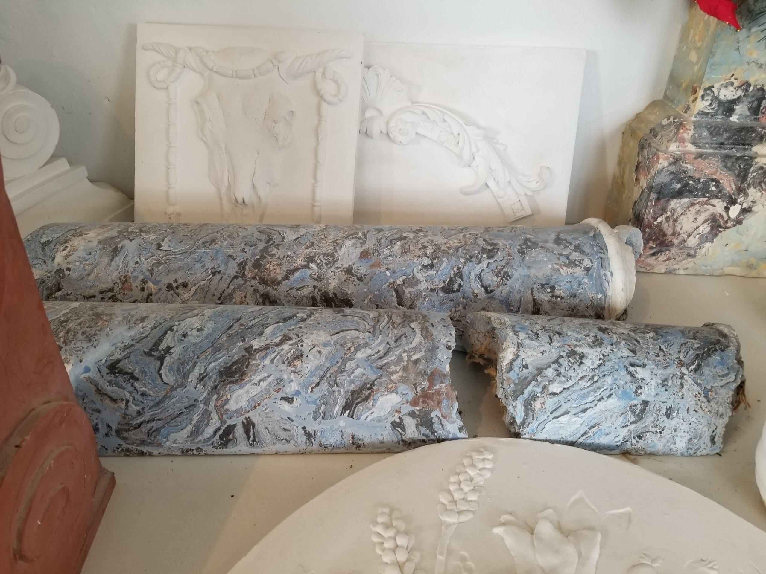
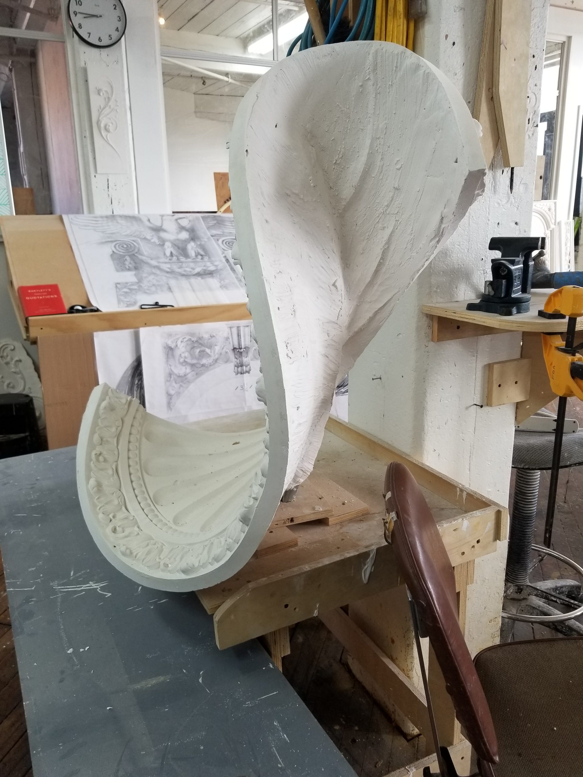
Museum Lab provides a unique context in which to explore the themes of the course. The ethos of the organization shares an emphasis on creative process and experimentation. The museum building also provides partially demolished remnants of the plaster craft central to our work this semester. Conceived as a ‘beautiful ruin” many of the ornamental details from the original architecture now read as incomplete. This partially deconstructed site provides an exciting context to imagine new affordances for a very old material. Our site visit in February was intended to familiarize you with the museum and give you an opportunity to document sites of interest.
Resources
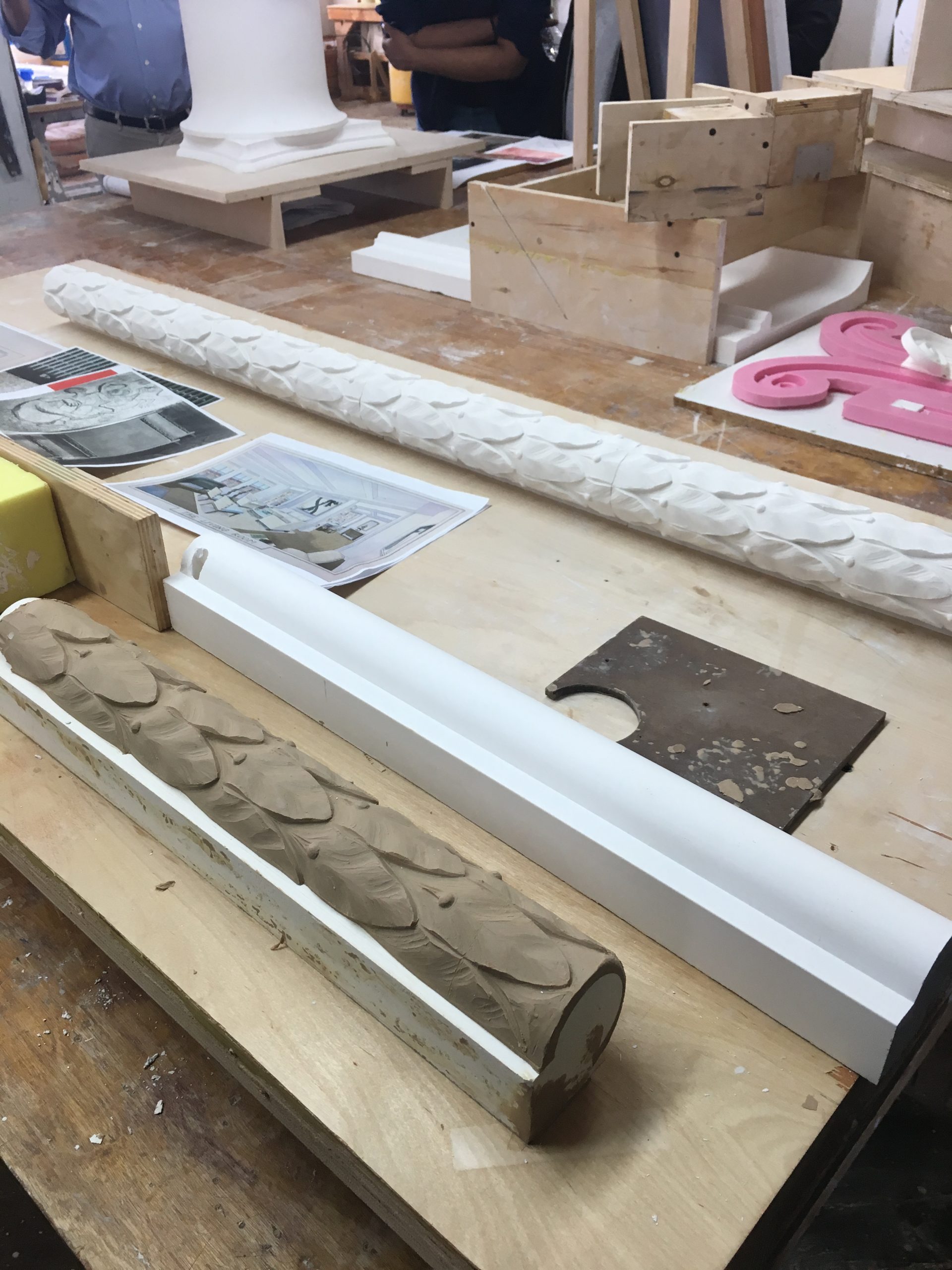
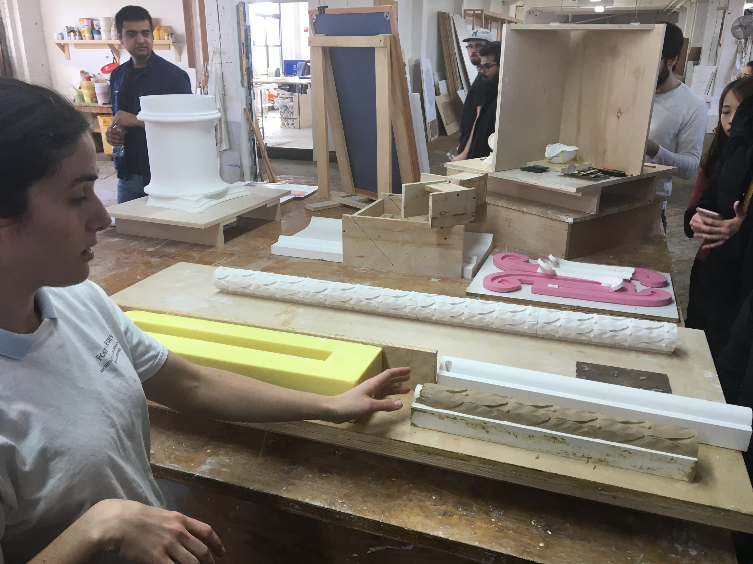
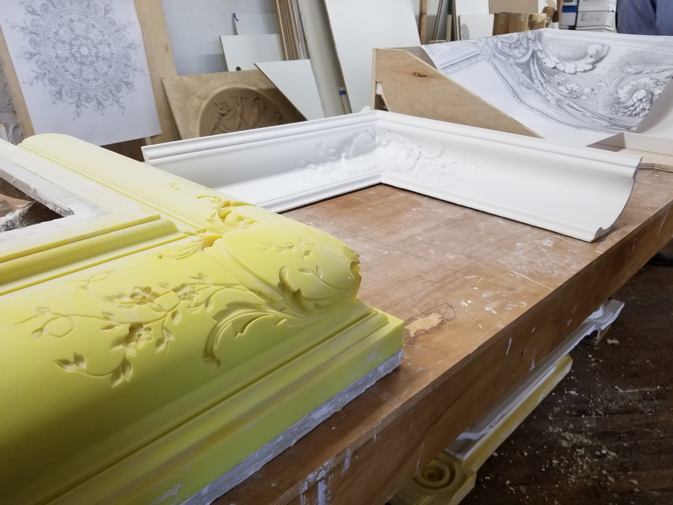
Running molds. Custom profiles combined with custom sled tracks or mechanisms can produce both straight or curved extruded forms.
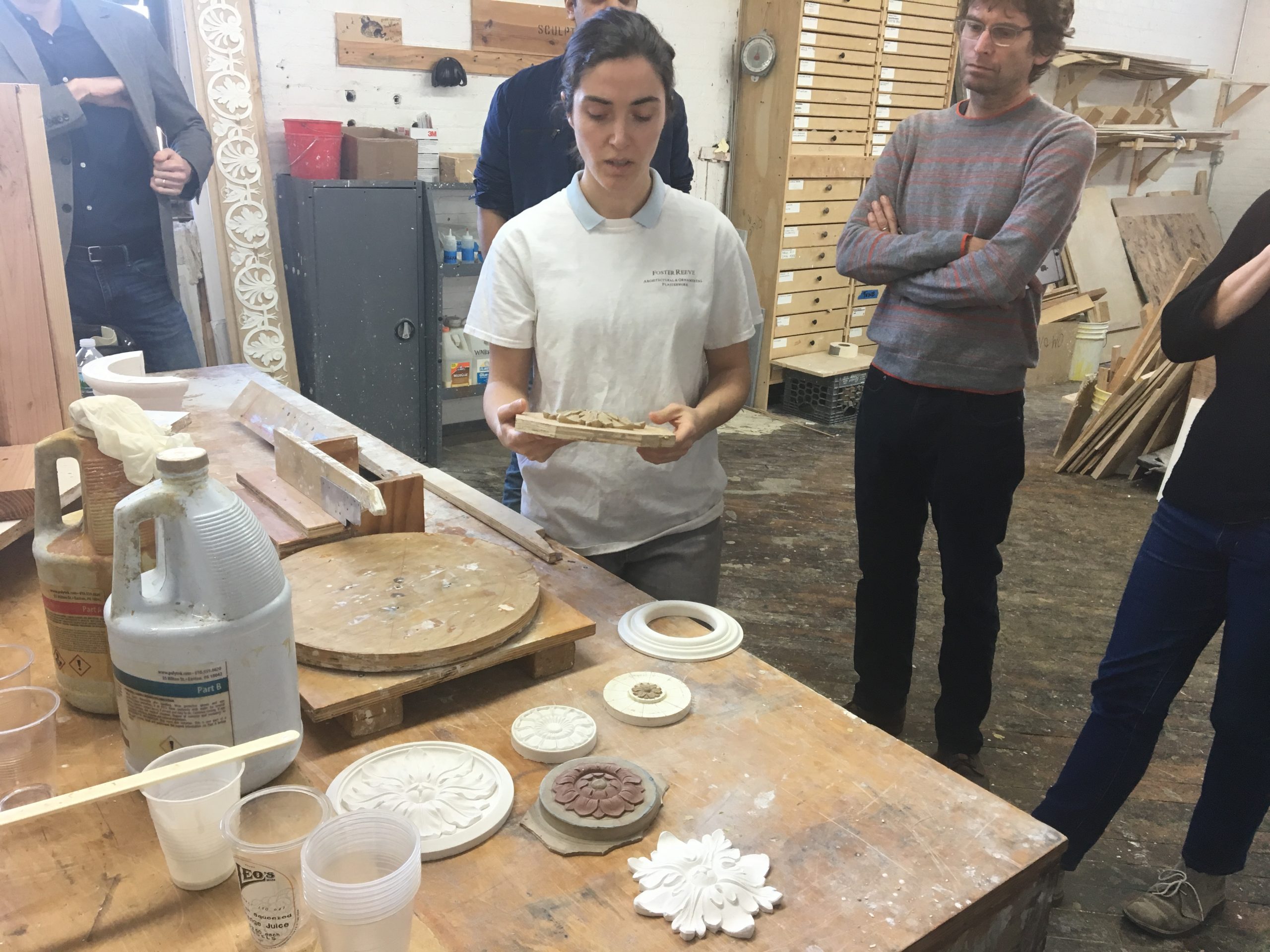
Polyurethane molds. Patterning for molds can incorporate a wide variety of materials, digitally fabricated forms, and handwork. If your idea would require the use of multiple molds or extremely large molds, please consult with the instructors.
Plaster molds. Convex plaster forms can be molded using a rigid plaster mold given suitable release agents. This is especially applicable to larger curves used as base forms.
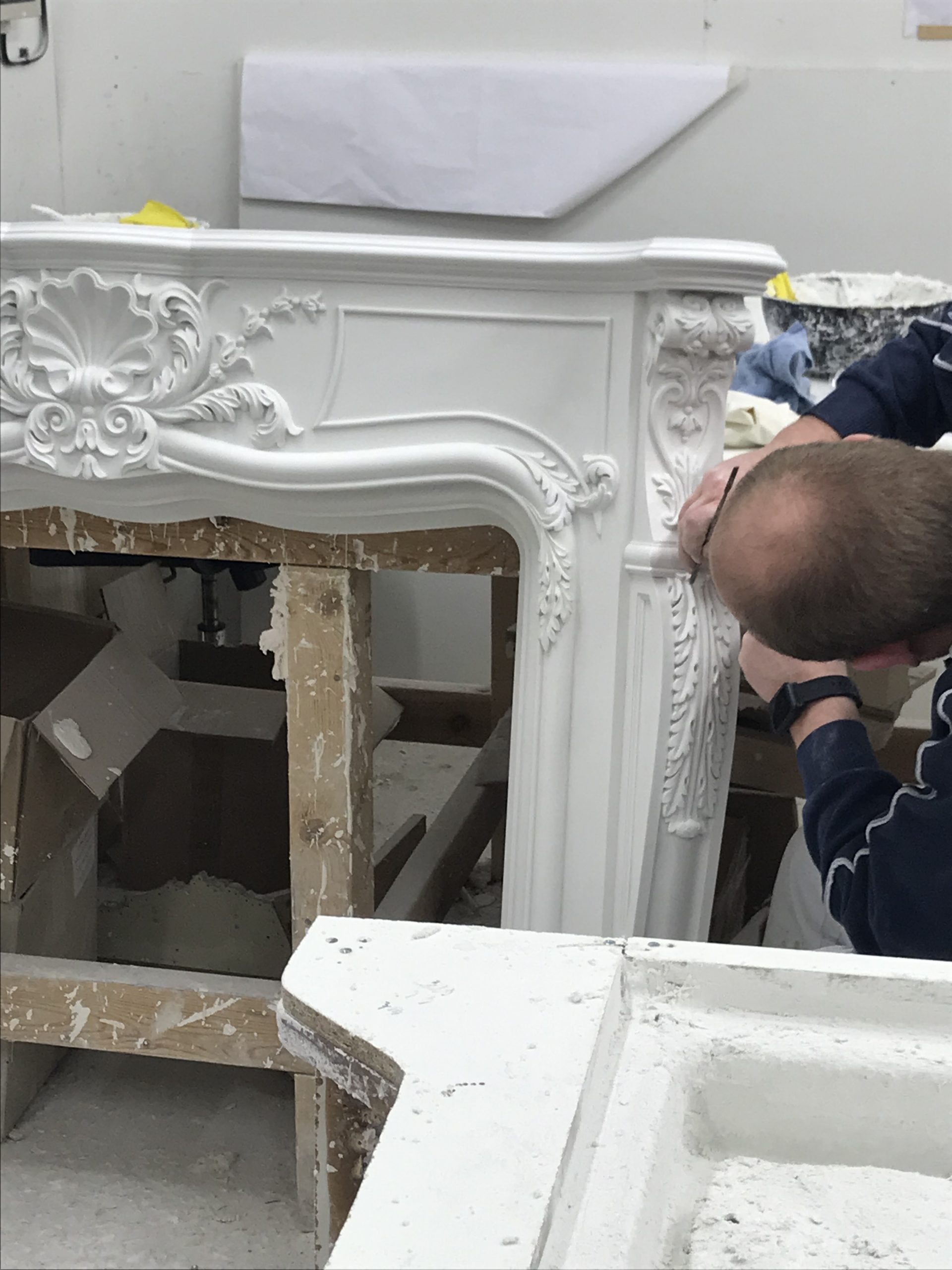
Troweling and tooling. Hand tools for plaster are used to render flat and textured surfaces. The addition of mechanism or custom jigs could add a systematic form to the treatment of surfaces with trowels, combs, and brushes.
Green plaster carving. Plaster in the initial stages of curing can be carved or cut.
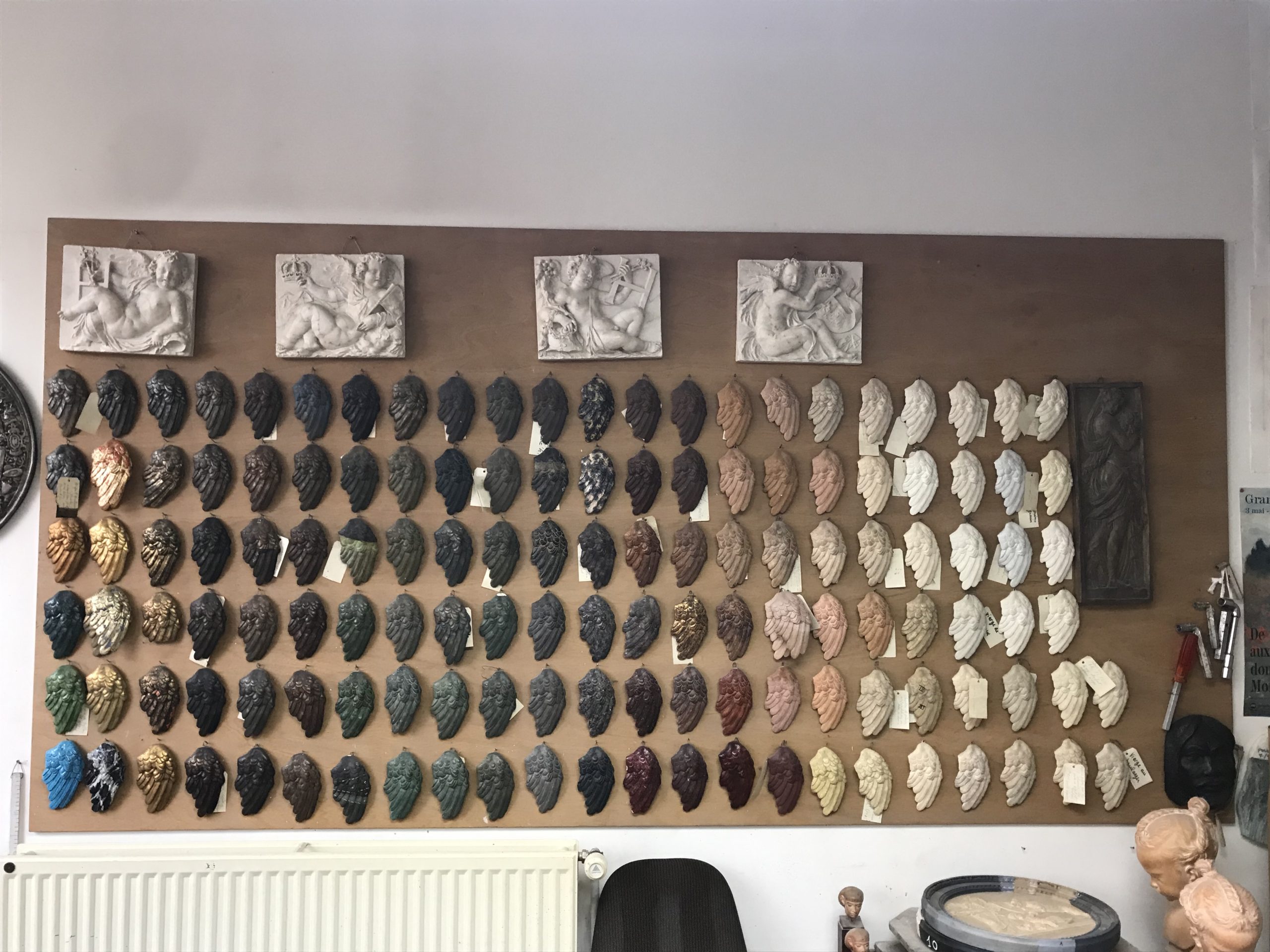
Color and inclusions. Plaster can be painted or also tinted using dry-powder pigments. Objects or granular aggregate material can be incorporated directly in wet plaster.
Idiosyncratic forming processes. There are boundless possibilities for casting plaster using ad hoc or single-use molds, or rendering onto armatures or lath forms. E.g., plaster could be cast directly into natural soil impressions.
Composition and accretion. Individual plaster elements can be assembled with other objects and worked material, either into mold patterns or directly into final artifacts.
Digital fabrication. Laser-cutting, 3D printing, CNC milling, algorithmic Grasshopper modeling, and parametric CAD.
dFAB Robot Lab. The workflow could include robotic manipulation of plaster. However, due to the short timeline, we discourage significant development of novel end-of-arm tooling. Please check with the instructors if you have questions about scope or feasibility. Groups working with the robot will need at least one member already certified to use the lab.
dFAB Motion Capture. The lab supports capturing tool trajectories in both batch mode and real-time. In batch mode, the system can generate a CSV file of rigid-body trajectory data for multiple objects, suitable for post-processing in Python or Grasshopper. For this project timeline, we discourage real-time interaction systems. Tool capture involves creating a custom marker fixture for the tool, calibrating the cameras and defining bodies, then developing a protocol for recording short well-defined movements.
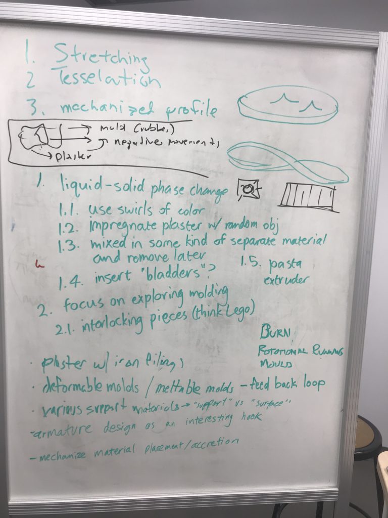
Prompts
A central thesis of Human Machine Virtuosity is that human skill can be deeply expressive in a way that is complementary to the precision and scalability of digital design tools. This is a middle path between pure traditional craft and industrial manufacturing, which uses mostly standardized processes.
For each workflow, a central question is identifying and locating the full decision process in space and time. A central tension exists between the abstracted decisions involved in CAD and algorithm and the embodied, tactile decisions involved in physical skill. So for example, if a candidate process is fully resolved during the digital fabrication stages, it is worthwhile to consider how meaningful decisions could be incorporated into plaster rendering process.
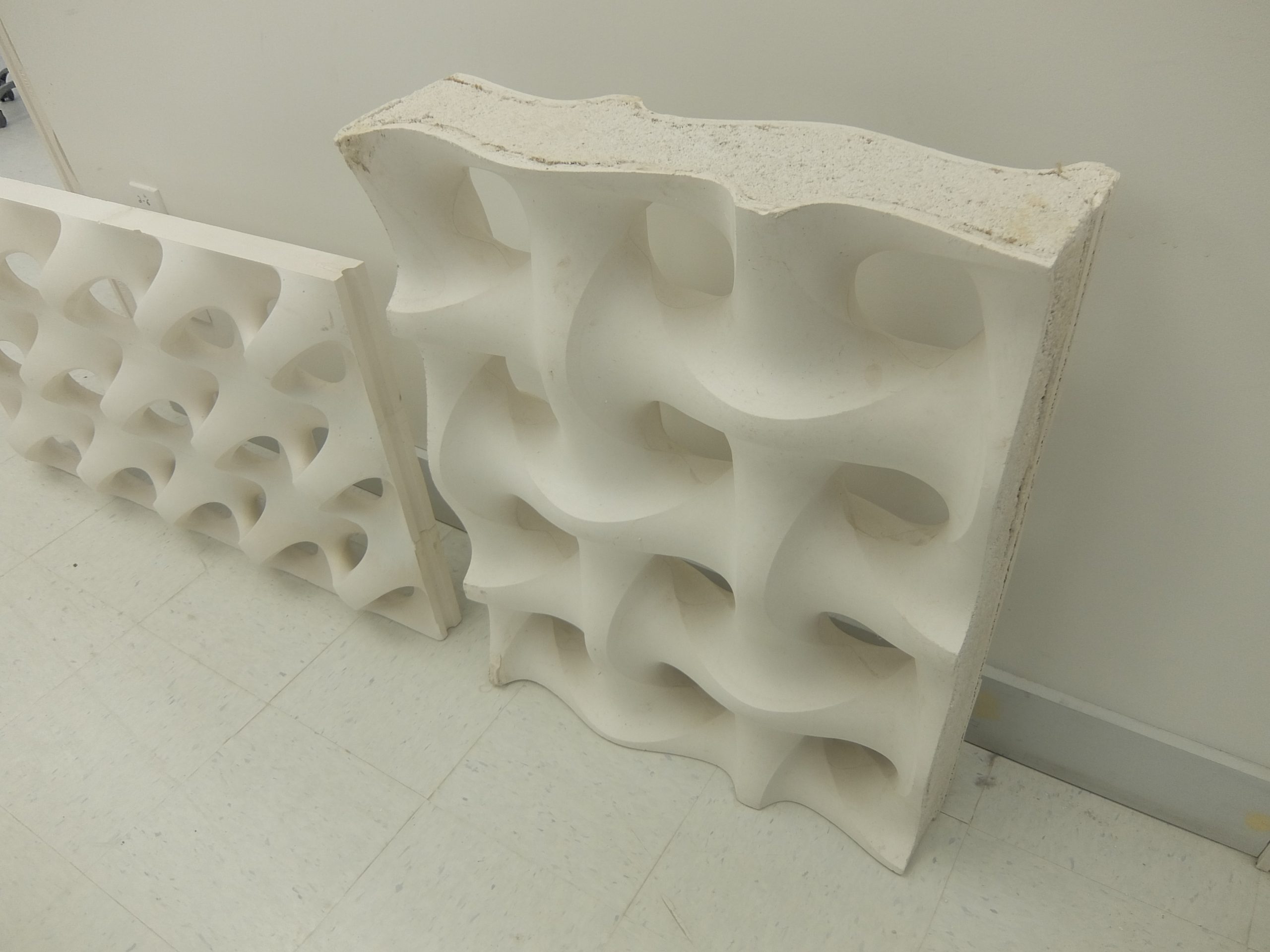
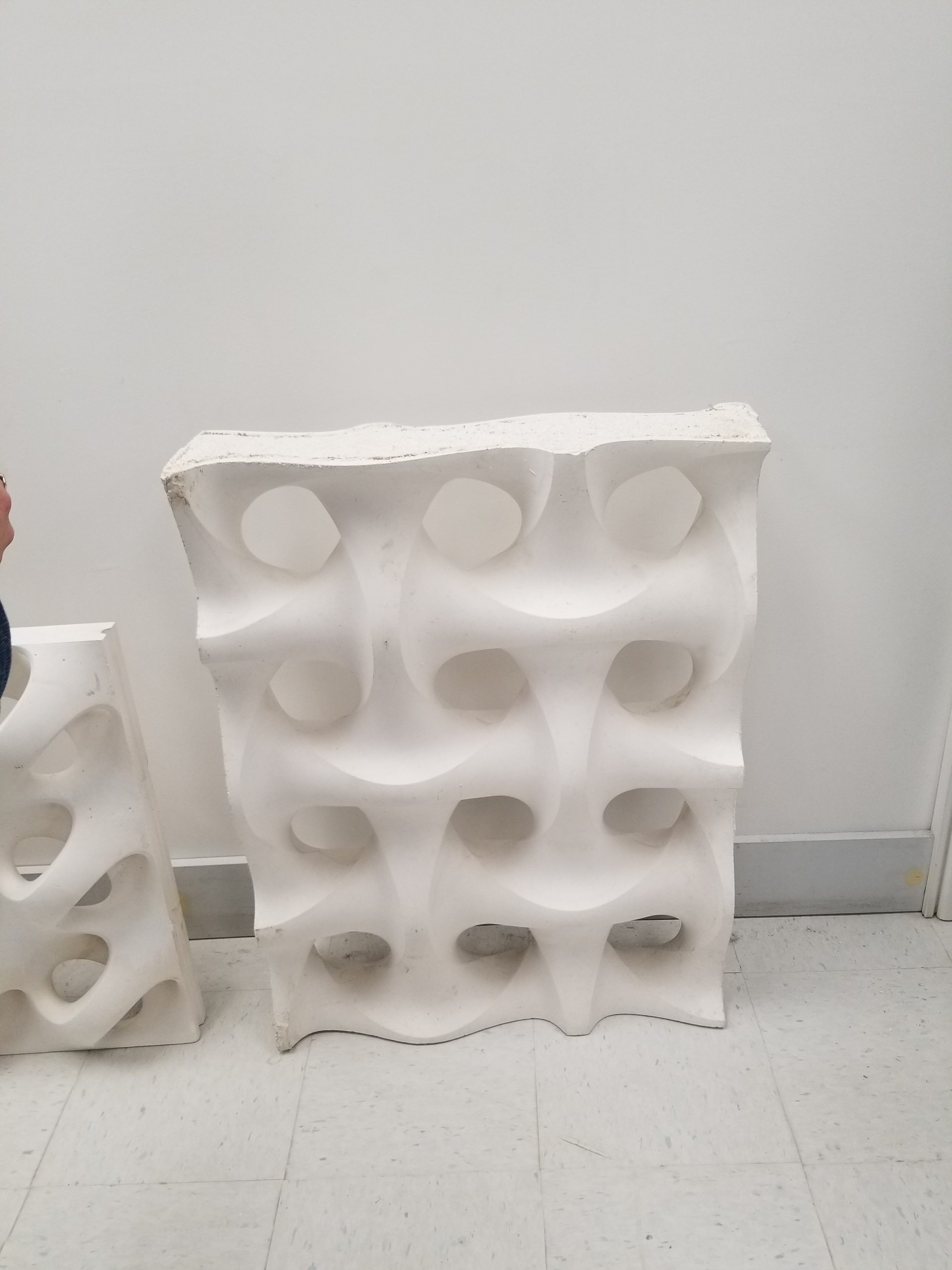
Modularity is a powerful heuristic for adding discrete tactile choices. So for example, a system of compatible shapes could be independently fabricated and then composed at final scale. Similarly, a mold with removable parts could defer decisions to the casting stage and generate a combinatorial design space.
Some degree of randomness is intrinsic to physical media, especially semi-liquids like curing plaster. This could be accentuated using deliberately random gestures such as allowing plaster to form free-flow layers, using drip application, or shattering cured material. These processes can require a great deal of tactile skill to create fully-considered effects in the midst of stochastic outcomes.
 ]]>
]]>
For this first project you will work in groups to develop a proof-of-concept design system, then apply it to produce two annular tiles fabricated in plaster. The resulting tiles will be sized to fill a section of the arch in the Museumlab studio lab space.
The key objective is the development and documentation of a workflow which incorporates appropriate elements of both digital design and expressive human skill and intuition. The production of sample tiles is the means to demonstrate the workflow. The success of the projects will be gauged along two trajectories:
- The system designed: The project creates an enjoyable and robust design experience, encouraging sustained practice and interaction.
- The work produced: The project results in the making of compelling and novel design artifacts which reflect the hybrid explorations.
Resources
Running molds. Custom profiles combined with custom sled tracks or mechanisms can produce both straight or curved extruded forms.
Polyurethane molds. Patterning for molds can incorporate a wide variety of materials, digitally fabricated forms, and handwork. If your idea would require the use of multiple molds or extremely large molds, please consult with the instructors.
Plaster molds. Convex plaster forms can be molded using a rigid plaster mold given suitable release agents. This is especially applicable to larger curves used as base forms.
Troweling and tooling. Hand tools for plaster are used to render flat and textured surfaces. The addition of mechanism or custom jigs could add a systematic form to the treatment of surfaces with trowels, combs, and brushes.
Green plaster carving. Plaster in the initial stages of curing can be carved or cut.
Color and inclusions. Plaster can be painted or also tinted using dry-powder pigments. Objects or granular aggregate material can be incorporated directly in wet plaster.
Idiosyncratic forming processes. There are boundless possibilities for casting plaster using ad hoc or single-use molds, or rendering onto armatures or lath forms. E.g., plaster could be cast directly into natural soil impressions.
Composition and accretion. Individual plaster elements can be assembled with other objects and worked material, either into mold patterns or directly into final artifacts.
Digital fabrication. Laser-cutting, 3D printing, CNC milling, algorithmic Grasshopper modeling, and parametric CAD.
dFAB Robot Lab. The workflow could include robotic manipulation of plaster. However, due to the short timeline, we discourage significant development of novel end-of-arm tooling. Please check with the instructors if you have questions about scope or feasibility. Groups working with the robot will need at least one member already certified to use the lab.
dFAB Motion Capture. The lab supports capturing tool trajectories in both batch mode and real-time. In batch mode, the system can generate a CSV file of rigid-body trajectory data for multiple objects, suitable for post-processing in Python or Grasshopper. For this project timeline, we discourage real-time interaction systems. Tool capture involves creating a custom marker fixture for the tool, calibrating the cameras and defining bodies, then developing a protocol for recording short well-defined movements.
Deliverables
- a report delivered as a post on the course blog including
- discussion of the system objectives
- a description of the design process in use
- video clip documenting the design process
- photos documenting the fabrication process
- two physical plaster tiles at scale to fit the site
Schedule
- Wed Feb 5: project release, team formation
- Mon Feb 10: Museumlab site visit
- Mon Feb 17: prototype review
- Mon Feb 24: in-class project presentations
Prompts
A central thesis of Human Machine Virtuosity is that human skill can be deeply expressive in a way that is complementary to the precision and scalability of digital design tools. This is a middle path between pure traditional craft and industrial manufacturing, which uses mostly standardized processes.
For each workflow, a central question is identifying and locating the full decision process in space and time. A central tension exists between the abstracted decisions involved in CAD and algorithm and the embodied, tactile decisions involved in physical skill. So for example, if a candidate process is fully resolved during the digital fabrication stages, it is worthwhile to consider how meaningful decisions could be incorporated into plaster rendering process.
Modularity is a powerful heuristic for adding discrete tactile choices. So for example, a system of compatible shapes could be independently fabricated and then composed at final scale. Similarly, a mold with removable parts could defer decisions to the casting stage and generate a combinatorial design space.
Some degree of randomness is intrinsic to physical media, especially semi-liquids like curing plaster. This could be accentuated using deliberately random gestures such as allowing plaster to form free-flow layers, using drip application, or shattering cured material. These processes can require a great deal of tactile skill to create fully-considered effects in the midst of stochastic outcomes.
Site Context
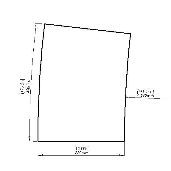
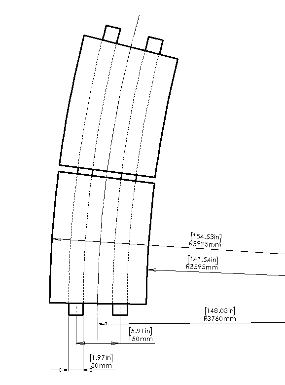
The purpose of your system is to produce one or more tiles which fit within an annular segment of the face of the arch in the studio lab. The exact dimensional specifications will be updated after we take measurements during the site visit.
Dimensions
The critical bounding box dimension for the tile is the 13″ maximum radial width. The arch is approximately circular; for short segments a circular edge should be fine. We measured the circular diameter at 283 inches on the inside edge of the face. The length is not critical, the template below assumes an arc length of approximately 18″.


The objective of the assignment is to prepare tooling for an in-class casting mold workshop on Jan 27 and Jan 29. We will group the class into pairs. Each pair will be responsible for fabricating a mold pattern to use in class. On Monday we will prepare the pattern in a mold box and create a rubber mold. On Wednesday we will cast plaster into the rubber molds.
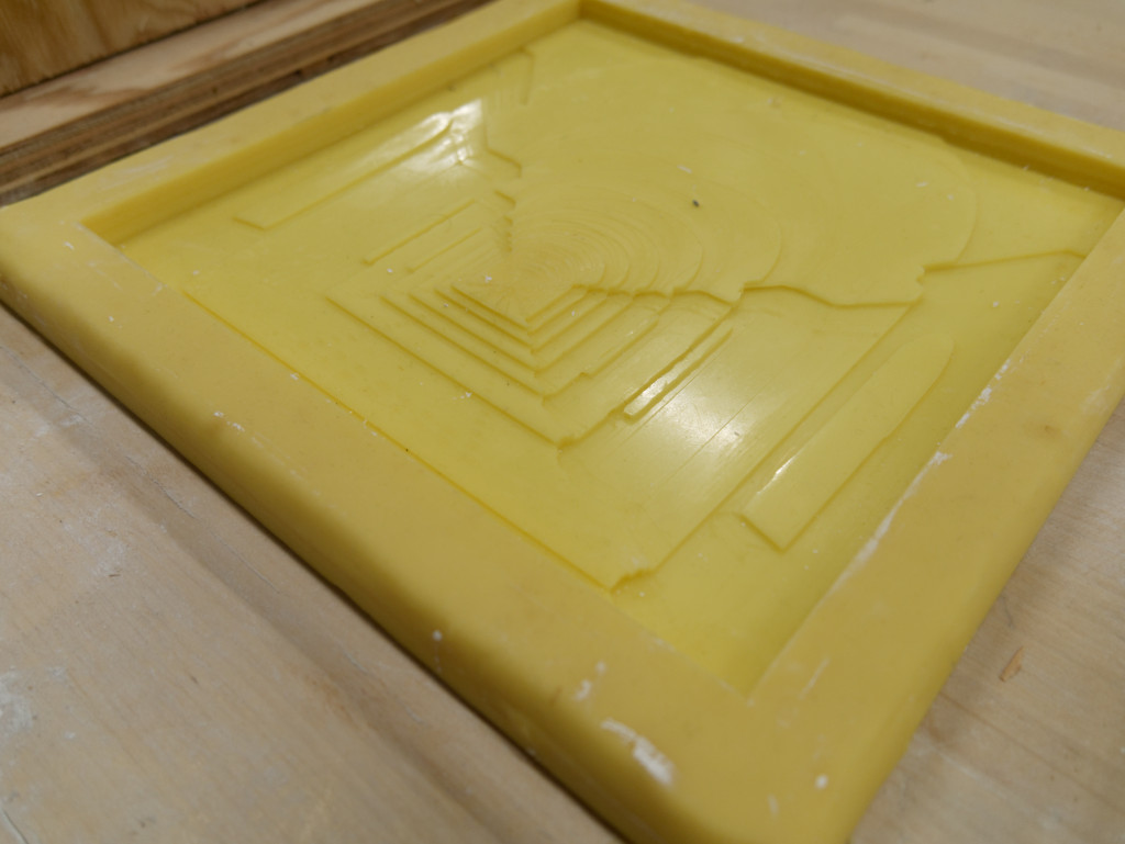
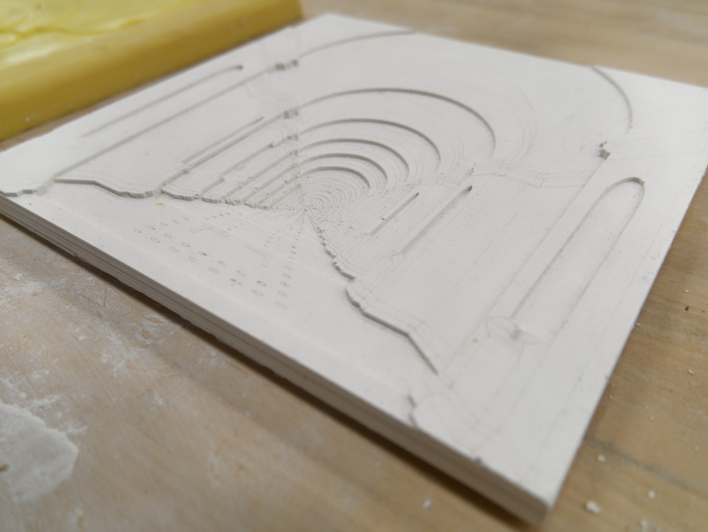
The pattern you create is a positive form in low relief. The resulting single-sided rubber mold will have the negative shape and include side walls to contain poured plaster. The plaster part will be upside-down in the rubber mold; the exposed back surface (on top during pouring) will be left open and be approximately flat.
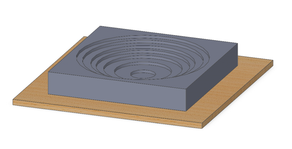
Pattern Dimensions
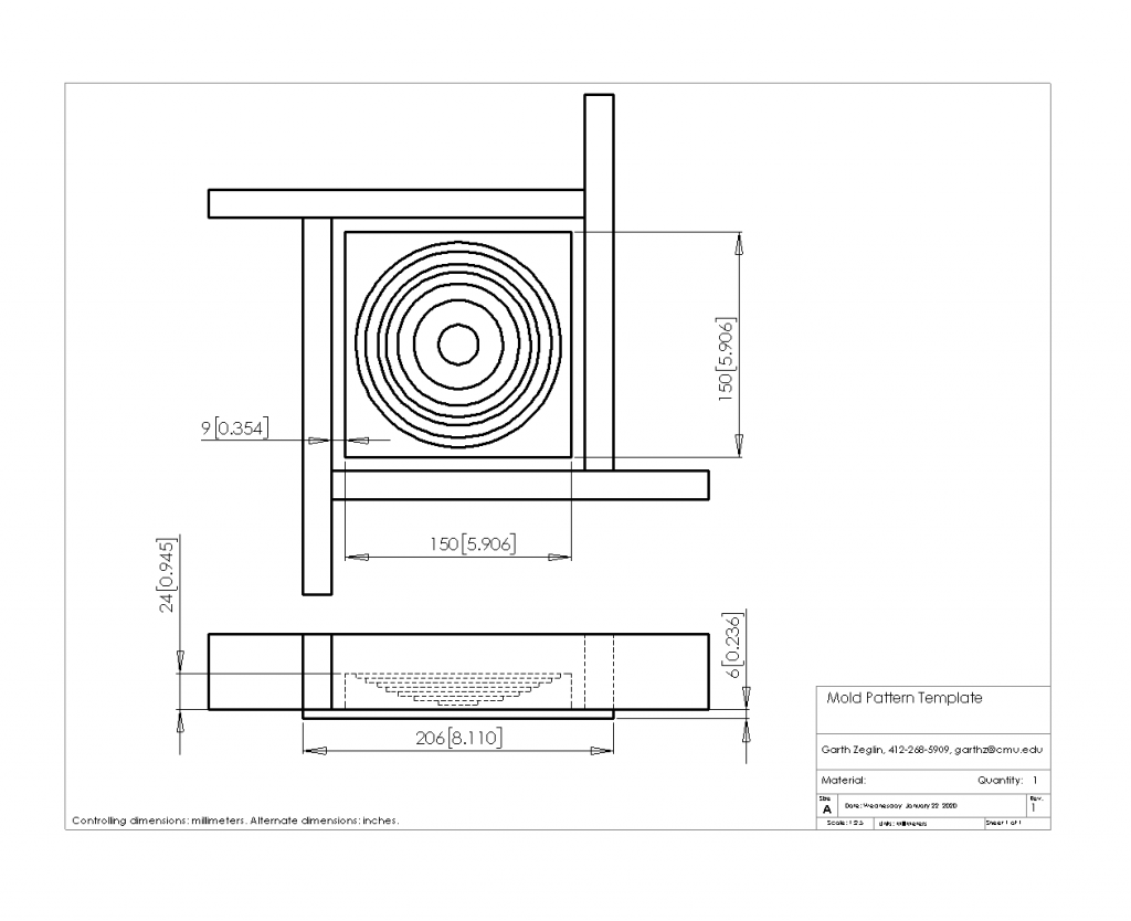
Below you will find both sample CAD files and photos of the demonstration pattern and mold. Your pattern object should occupy a volume of no more than 150x150x24 mm (6x6x1 inch) and be mounted on a backing plate large enough to mount the mold box walls with clearance for the side walls of the rubber mold. A reasonable rubber side wall thickness is 9mm (3/8 in), and the mold box walls are 19mm (3/4 in) plywood, so the backing plate is typically at least 28mm (1 1/8 in) larger than the pattern on each side. The backing plate can be lightweight; we recommend 6 mm plywood.
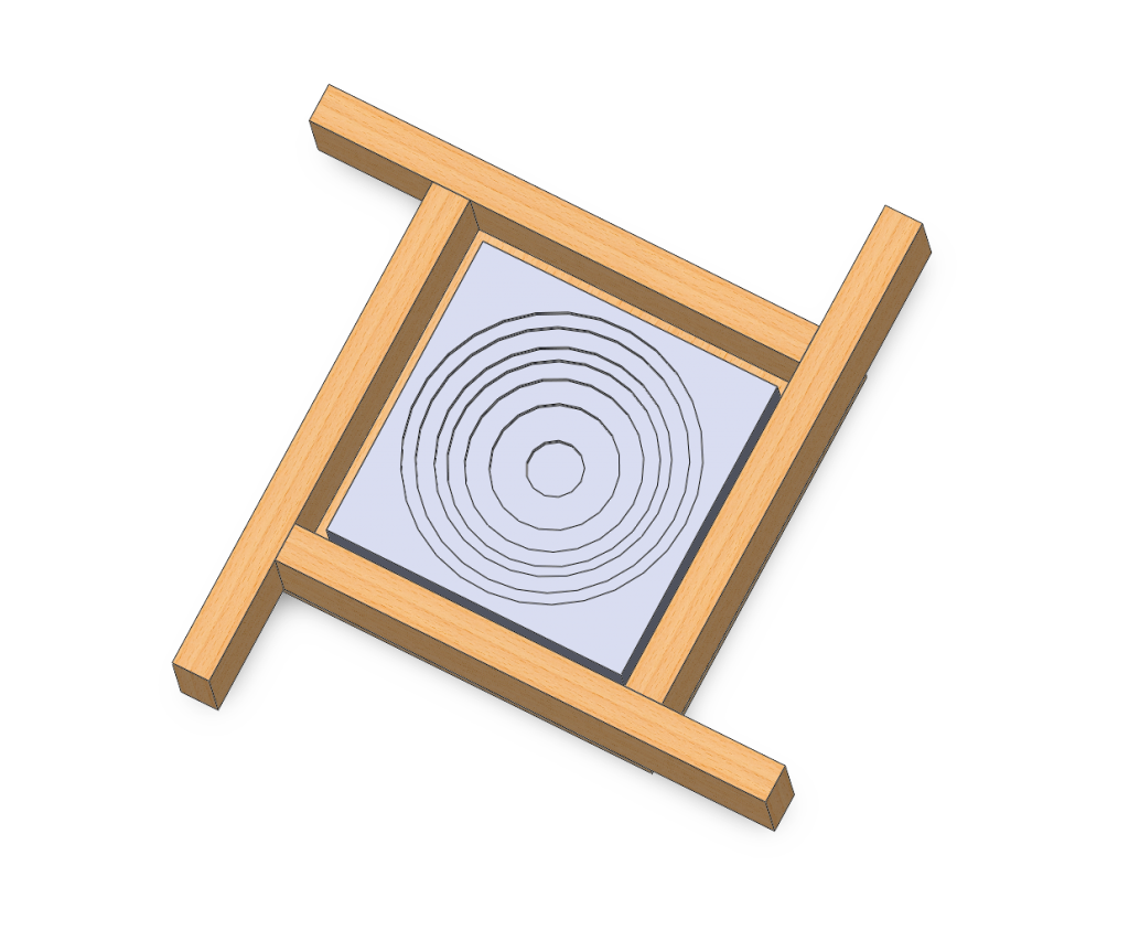
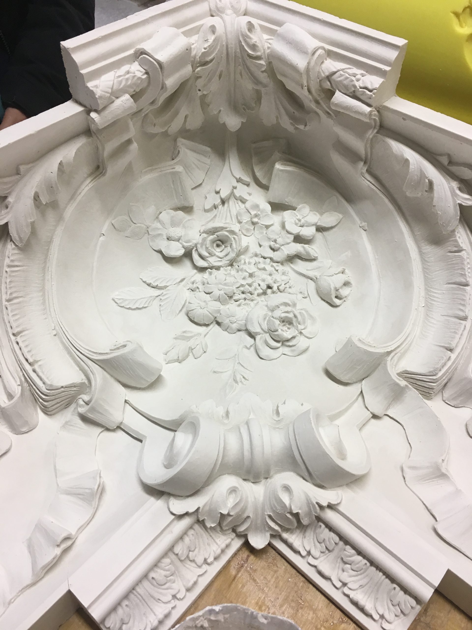
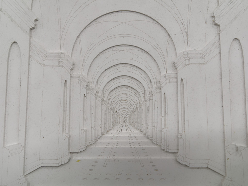
The demonstration pattern below was created using eight layers of laser-cut 3mm acrylic bonded together, although you may choose to make a shallower profile. The pattern includes geometric low relief as well as etched linework. The rubber and plaster can both carry fine detail. The rubber is flexible enough to pull off corners and out of pockets, but please avoid undercuts, and recognize that deep vertical surfaces or narrow holes may make demolding a challenge. Please remember that the final part will be in plaster, so an overly thin pattern may be very fragile.
You may also use other materials in the pattern, e.g. hand-worked clay, wax, or small found objects. The example is image-based, but any sort of literal or abstract geometry or image composition which fits within the bounds is acceptable.
If assembling a pattern from parts, please be sure to bond any layers together firmly; if gluing acrylic, clamp firmly. The rubber has low viscosity and will seep into tiny openings or textures.
Sample Files
The zip includes a SolidWorks template for the pattern and mold. The PDF is the drawing showing critical dimensions.
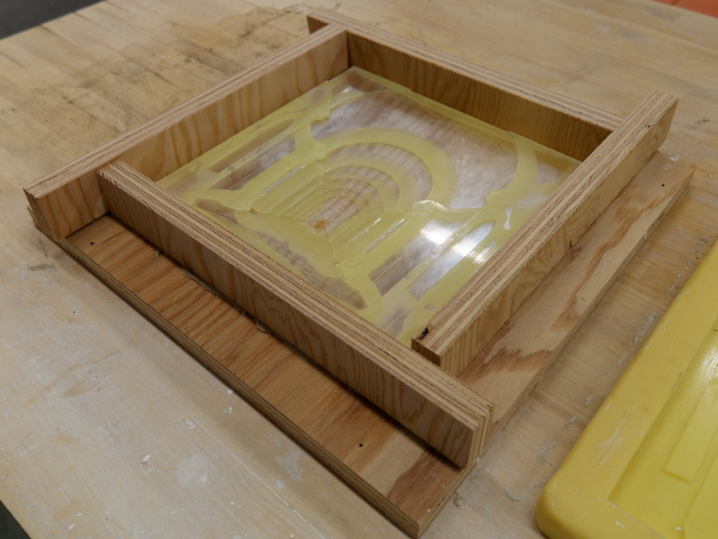
Demonstration Mold
Materials
We will be using Poly 74-20 Liquid Rubber, a two-part liquid polyurethane.
Please bring a hot glue gun on Monday (if you have one) to use in assembling the mold box.
We will use Plasticine clay to seal openings in the mold box.
We will cast using USG Moulding Plaster, same as for the running mold.
Estimated Volumes and Mass
The bounding box for the pattern has a volume of 540 cc, so the maximum plaster mass is about 800 grams (1.8 lbs), but could be substantially less, depending on the specific contours.
The rubber is typically poured about 6 to 8 mm higher than the highest pattern feature. With 9 mm wall thickness, the absolute maximum block volume is about 850 cc, but of course some of that is displaced by the pattern. The absolute minimum would be about 300 cc (850-540, e.g. a solid pattern. The rubber has a specific gravity near 1.0, so a typical 450 cc mold weighs about 450 grams (1 lb). For reference, the rubber is about $8.50/lb.
Mix Ratios
The PolyTex 74-20 rubber specifies a mix ratio of 1A:2B by mass. In other terms, the Part A component is 33.3% of the total mass, and the Part B component is 66.6%. E.g. 450 grams of rubber requires 150 grams of Part A and 300 grams of Part B. Part B should be stirred before use. The pour time is 20 minutes, so we’ll need to work quickly after the parts are combined. The demold time is 16 hours.
The USG data sheet suggests a range of mix ratios, between 63 to 70 lbs of water per 100 lbs of plaster. In other terms, the water constitutes between 38.7% and 41.2% of the total mass of the mixed plaster. E.g. assuming a mid-range 40% water rate, 1 kg of plaster (2.2 lbs) would use 400 grams water and 600 grams dry plaster.
]]>