The Development of Bow.
Project Overview:
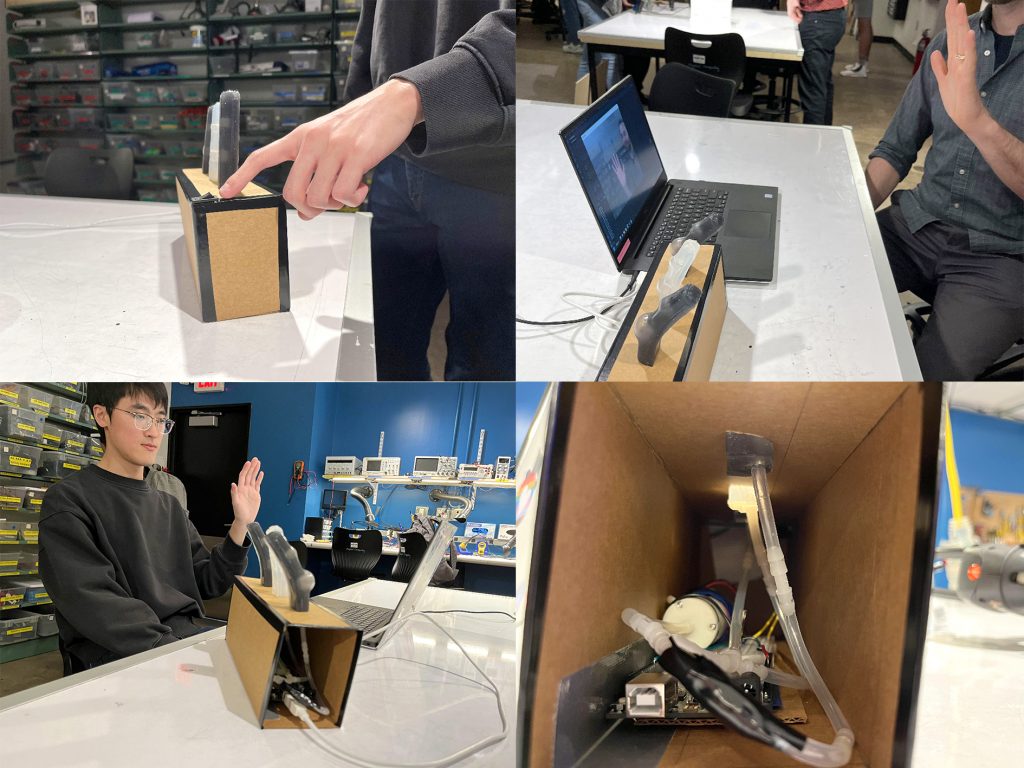
Bow. is an interactive silicone robotic display. The display utilizes a camera to detect a user’s hand (wave) and, when a hand is present, reacts to the user. The display’s reaction is a mix between a wave and a bow.
Project Objectives:
The objective of our project was to create a finger-like pneumatically actuated silicone finger. Our immediate goal was to create a part which, when inflated via an air pump, bent in a way which mirrored a human finger. The loftier goal, which we were unable to complete during the duration of the course, was to develop the part so that it could attach itself to a user’s hand similarly to a brace or exoskeleton. In developing this part, we aimed to further our understanding of cavity geometry, specifically how it affected the inflation and actuation of a soft robotic part.
Creative Design Reflection:
The use of silicone in casting our part allowed us to mirror the fluidity and softness of a real finger’s movement. Additionally, with regard to the concept of attaching it to the user’s hand, we liked the fact that, although the part’s actuation would guide the user’s movement, the softness of the material would allow for the user to pushback/reject movements with far less strain than would be required to pushback against a hard exoskeleton.
In the end, we really enjoyed the fact that, although we did not attach the part to users’ hands, the softness of the material enabled far more user interaction than a harder material would have. At multiple times during the show, we witnessed users poking, prodding, and physically interacting with the parts. Being able to poke them — both while inflated and not — and watch their gelatinous recoil ended up being a fan favorite of those who came by our piece; while this was not intended, it added to the display greatly by allowing physical interaction, rather than only being able to engage through a computer screen.
Lastly, the use of soft technology added a shock-factor and intrigue to our display. When the piece inflates, two air pockets very obviously grow. Because of the softness of the material we used, these pockets seemingly came out of nowhere (as opposed to say, a balloon which is visually limp and deflated). Before engaging with our display, users weren’t quite able to tell what the movement of the part was going to be due to the parts’ opaqueness/translucency, so when the inflation and air pockets came seemingly out of nowhere, they were further enthralled.
Outcomes:
Successes
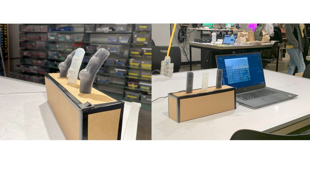
- We were able to trial many different cavity designs and settle on both a shape and size (relative to the length and width of the part) which best achieved the inflation angle we desired
- We designed, fabricated, and programmed an Arduino circuit which used computer vision input to control air pumps
- We created an interactive display showcasing our research and creative display design.
Failures
- We were unable to iterate on our design so that the user would be able to wear our part to undergo guided movement. We prototyped multiple different designs for this concept but did not get them to a showcase-able state in time for Rubbery Things.
- We aimed to have a more complicated script which took into account specific user gestures to control the piece in a more complex way. Due to fabrication timing as well as the limitations of OpenCV via a serial bus, we were unable to update the motor state as rapidly as this goal would require to prevent popping the piece.
- Although we were able to work around the issue by using an Arduino, we were not able to get a Raspberry Pi Pico to successfully trigger the motors. We’re still not sure why this failed, but were luckily able to switch gears and re-adapt our code to utilize an Arduino shortly before the show.
Technical Documentation
CAD Files:
All of the files linked below were created using SolidWorks, however, many of the designs were originated/conceived using Rhino software.
We designed our part by first 3D modeling the part we wished to obtain by pouring silicone into a mold. From there, we split the part vertically, and used each half to create cavities in a solid block. Lastly we needed to perform a complex split of the remaining part(s) of the block to create our mold top and bottom. The CAD files for our first iteration can be found here.
We continued iterating on our part by adhering a solid piece of silicone to the bottom in order to increase the thickness of the bottom of the part to achieve a more ideal bend. We do not have CAD parts for this piece, as it was poured from a stock mold found in the fabrication lab. The piece was trimmed to fit the surface area of the original, bonded part; the piece thickness was ~6mm.
Due to 3D printing delays, we were unable to iterate on the cavity shape as frequently as we had liked. The makeup for lost time, we developed a part which would allow us to cast and test six of our most promising cavity designs with 1 3D print. The files for this design can be found here.
Lastly, we combined the observations and results of testing multiple designs with minimal 3D prints into our final design. Luckily, this worked nearly perfectly, was easy to both pour and pull, and exceeded our expectations for Rubbery Things. The files for the final iteration can be found here.
Code Files:
Our original code can be found here. This code contains both Python files intended to be run on a computer, as well as MicroPython files intended to be run on a Raspberry Pi Pico. Some test files work as intended, however, the final display shown at Rubbery Things is not able to be achieved with this code.
Our final code can be found here. This is the code that was used during the final show. The folder contains Arduino code intended for an Arduino Uno and Python code for a computer. In order to successfully run this code, some elements (including port names, pin numbers, etc.) will need to be updated by the user.
Citations:
“Creating a Hand Tracking Module Using Python, Opencv, and MediaPipe.” Section, https://www.section.io/engineering-education/creating-a-hand-tracking-module/.
M. N. Golchin, A. Hadi and B. Tarvirdizadeh. Development of A New Soft Robotic Module Using Compressed Air and Shape Memory Alloys. In 2021 9th RSI International Conference on Robotics and Mechatronics (ICRoM), Tehran, Iran, Islamic Republic of. 517-522. https://doi.org/10.1109/ICRoM54204.2021.9663519
Partner Contributions
Maddie:
- Created final CAD files for finger parts (SolidWorks)
- Designed and fabricated circuit
- Wrote Raspberry Pi Pico, Arduino, and Python scripts
- Maintained and authored documentation
- Created conceptual sketches
Xiaofan:
- Spearheaded initial design research
- Designed and built finalized display box
- Designed hinge components
- Created final project video
- Wrote weekly updates for the group
Both:
- Conceived final project display concept
- Pour and bonded silicone parts
- Continuously researched and updated cavity design