The automatic plant rotater helps indoor plant owners ensure that their plant gets even exposure to sunlight, even when the source of sunlight is one directional. This reduces the amount that a plant will grow to one side, which can result in an undesirable aesthetic, and in extreme cases, a plant that needs additional weights and staking to stay up. A common solution is for the caretaker to rotate the pot regularly, but this can be a difficult task to keep track of. See the picture below for extreme case of succulents trying to seek out the light (and an owner irregularly rotating the pot for correction)!

The hormone auxin is commonly responsible for triggering a plant to grow towards the light. Unless a plant is irregularly shaded in its environment, this hormonal response usually encourages plant to grow upward.
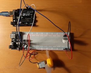
A light sensor is placed near the plant, on the side exposed to the most amount of light. It measures the light exposure at regular intervals, and when it has detected the “preferred total exposure” it will rotate the plant by a quarter turn. Since sunlight will vary throughout the day, the plant rotates based on exposure instead of based on a timer. If desired, the owner can press a button to rotate the plant before the “preferred total exposure” is reached, which allows for greater control.
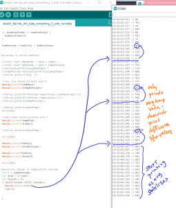
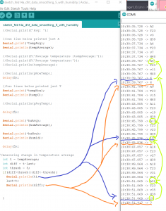
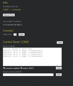
When connected to p5js, each time the plant turns, information about the latest total light sum (light exposure since the last turn), the preferred total exposure, and the total number of turns is sent through the Serial Port to p5js. The P5js sketch below does several tasks:
- Lists the array of numbers sent from the Arduino
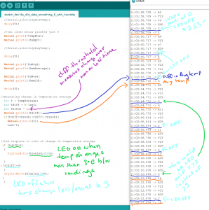
- Calculates “percent complete” which is a percentage of Total Light Exposure Since Last Turn/Preferred Total Exposure. For turns triggered by the sensor, we would expect this number to be about 100% while it could be anything lowered when the turn is triggered by a button press. If the plant is exposed to a significant amount of light at once, the number could be over 100%.
- Illustrates the Total Light Exposure adjacent to the Preferred Total Exposure to provide a user with a visual.
- If the Percent Complete value falls within a defined range (ex: 60-125%), there will be a smiley face on the screen. If the value falls outside of this range, a frowny face will appear instead. The visualization provides a quick reference for the user to understand what is going on without having to interpret the numbers flashing on the screen.
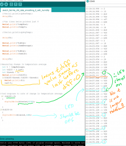
Arduino Sketch:
//motor and light sensor

#define lightPin A0 //Ambient light sensor reading
#include <Stepper.h>

//data smoothing and light sensor
const int numReadings = 100;
float ligReadings [numReadings];
int ligReadIndex = 0;
float ligTotal = 0;
int inputPin = lightPin; //put sensor pin here
float ligPer=0;
float light_percent=0;
int prefLigExp=150;

//stepper motor
int stepsPerRevolution = 2048; //see motor spec sheet
int motSpeed = 10;
int dt = 500;
Stepper stepmot(stepsPerRevolution, 8, 10, 9, 11); //see motor and driver specs

//for millis
unsigned long lastReadTime = 0;

//for button
const int buttonPin = 2;
int buttonValue = 0;

//p5jsturncount
int numberOfTurns = 0;

void setup() {
  pinMode(lightPin, INPUT);
  pinMode(buttonPin, INPUT_PULLUP);

  for (int thisReading = 0; thisReading < numReadings; thisReading++) {
    ligReadings[thisReading] = 0;
  }

  Serial.begin(9600);
  lastReadTime = millis();
  stepmot.setSpeed(motSpeed);

}


void loop() {
  //millis and light sensor
  if ((millis() - lastReadTime) >= 5000UL) {
    //Serial.println(lastReadTime);
    //Serial.println(millis());
    lastReadTime = millis();
    //light sensor read
    float light = analogRead(lightPin);
    float light_ratio = light / 1023.0;
    float light_percent = light_ratio * 100;

    ligTotal = ligTotal - ligReadings[ligReadIndex];
    ligReadings[ligReadIndex] = light_percent;
    ligTotal = ligTotal + ligReadings [ligReadIndex];
    ligReadIndex = ligReadIndex + 1;


  }

  buttonValue = digitalRead(buttonPin);


  if (buttonValue == LOW) {
    stepmot.step(stepsPerRevolution / 4);
    numberOfTurns=numberOfTurns+1;
    Serial.print(ligTotal);
    Serial.print(",");
    Serial.print(prefLigExp);
    Serial.print(",");
    Serial.println(numberOfTurns);
    ligTotal = 0;
  }


  if (ligTotal >= prefLigExp) {
    stepmot.step(stepsPerRevolution / 4);
    numberOfTurns=numberOfTurns+1;
    delay(3000);
    Serial.print(ligTotal);
    Serial.print(",");
    Serial.print(prefLigExp);
    Serial.print(",");
    Serial.println(numberOfTurns);
    //make step stop rotating
    ligTotal = 0;
    //ligReadIndex=0;
  }

  else {
    stepmot.step(0);
  }


}
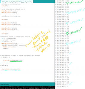
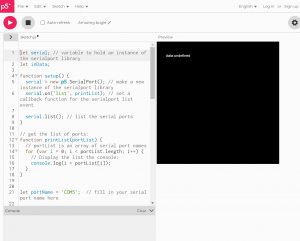
p5js Sketch:
//smiley sketch: https://medium.com/spidernitt/introduction-to-digital-art-with-p5-js-d8ba63080b77
//serial, sensors, arrays, and p5js: https://www.youtube.com/watch?v=feL_-clJQMs

let serial;
let sensors = [256,256,0];
let newData = "waiting for data";
let px, py;
let rad1;
let rad2;
let rad3;
let potDiameter;

function setup() {
  createCanvas(windowWidth, windowHeight);
  stroke(255);
  let radius = min(width,height)/2;
  let rad1=radius*0.7;
  let rad2= radius*.5;
  let rad3= radius*.25
  px= width/2;
  py = height/2;
  potDiameter = radius*1.5
  serial = new p5.SerialPort();
  serial.list();
  serial.open('COM5');
  serial.on('connected', serverConnected);
  serial.on('list',gotList);
  serial.on('data',gotData);
  serial.on('error',gotError);
  serial.on('open',gotOpen);

}

function serverConnected() {
  print("Connected to Server");
}

function gotList(thelist) {
  print("List of Serial Ports:");

  for (let i=0; i < thelist.length; i++) {
    print(i + " " + thelist[i]);

  }
}

function gotOpen() {
  print("Serial Port is Open");
}

function gotClose() {
  print("Serial Port is Closed");
  newData = "Serial Port is Closed";
}

function gotError(theerror) {
  print(theerror);
}

function gotData() {
  let currentString = serial.readLine();
  trim(currentString);
  if (!currentString) return;
  sensors=split(currentString, ',');
  console.log(sensors);
  newData = currentString;
}


function draw() {
  background(255,255,255);
  fill(50,25,0);
  strokeWeight();
  text(newData,10,10);

  //numTurns=newData
  //text(numTurns,px,py)

  totExp=sensors[0];
  prefExp=sensors[1];
  numTurns=sensors[2];
  //strokeWeight(.5);
  text("Turn:"+ numTurns,px,py+75);
  perc = (totExp)/(prefExp)*100;
  text("Percent Complete:"+ perc,px,py+90);

  text("Preferred",px+60,py+20);
  noStroke();
  fill(200, 150, 0);
  rect(px+55,py, 55,-sensors[1]);

  strokeWeight(1);
  fill(50,25,0);
  text("Received",px,py+20);

  noStroke();
  fill(200, 200, 0);
  rect(px,py,55,-sensors[0]);

  if (perc >=60 || perc <=125) {
    smiley(px, py-10, 30);
  }
  if (perc <60 || perc >125) {
    frowny(px,py-10,30);
  }


function smiley(x, y, diameter) {
  // Face
  fill(255, 255, 0);                  //fills the face with yellow color
  stroke(0);                          //outline in black color
  strokeWeight(2);                    //outline weight set to 2
  ellipse(x, y, diameter, diameter);  //creates the outer circle

  // Smile
  var startAngle = 0.1 * PI;          //start angle of the arc
  var endAngle = 0.9 * PI;            //end angle
  var smilediameter = 0.5 * diameter;
  arc(x, y, smilediameter, smilediameter, startAngle, endAngle);

  // Eyes
  var offset = 0.15 * diameter;
  var eyediameter = 0.05 * diameter;
  fill(0);
  ellipse(x - offset, y - offset, eyediameter, eyediameter);
  ellipse(x + offset, y - offset, eyediameter, eyediameter);
}

  function frowny(x, y, diameter) {
  // Face
  fill(255, 150, 0);                  //fills the face with yellow color
  stroke(0);                          //outline in black color
  strokeWeight(2);                    //outline weight set to 2
  ellipse(x, y, diameter, diameter);  //creates the outer circle

  var startAngle = 1.2 * PI;          //start angle of the arc
  var endAngle = -0.2 * PI;            //end angle
  var smilediameter = 0.5 * diameter;
  arc(x, y+8, smilediameter, smilediameter, startAngle, endAngle);

  // Eyes
  var offset = 0.15 * diameter;
  var eyediameter = 0.05 * diameter;
  fill(0);
  ellipse(x - offset, y - offset, eyediameter, eyediameter);
  ellipse(x + offset, y - offset, eyediameter, eyediameter);
}


}