Watching the video I had a rough idea of how copiers worked in the modern era with sensors that sense the image and convert it into a file which it can then print multiple times. This was completely different to how photocopiers actually ran in the past which was very interesting to me. The way that one would photocopy something in the past would use a fine layer of powder deposited onto the piece of paper through a series of electrode wires and rollers. The paper would then run past a heater which would melt the toner onto the paper resulting in the final product. While watching him describe this process, the fact that papers came out warm from printers made so much more sense. The complex mechanical processes behind these printers was also very interesting to look at and learn about. I never realized how mechanically intensive the printing process used to be up until very recently. Finally, I thought the process of using electrons to transfer the negative an image was very interesting because it made for some movie magic like videos. For instance, when he would transfer the image onto the selenium, there would be nothing visible until he poured the powder on top and only where the charge remained would the powder stick. I thought this process was very cool.
Author: judsonk@andrew.cmu.edu
Assignment 5 – Jud
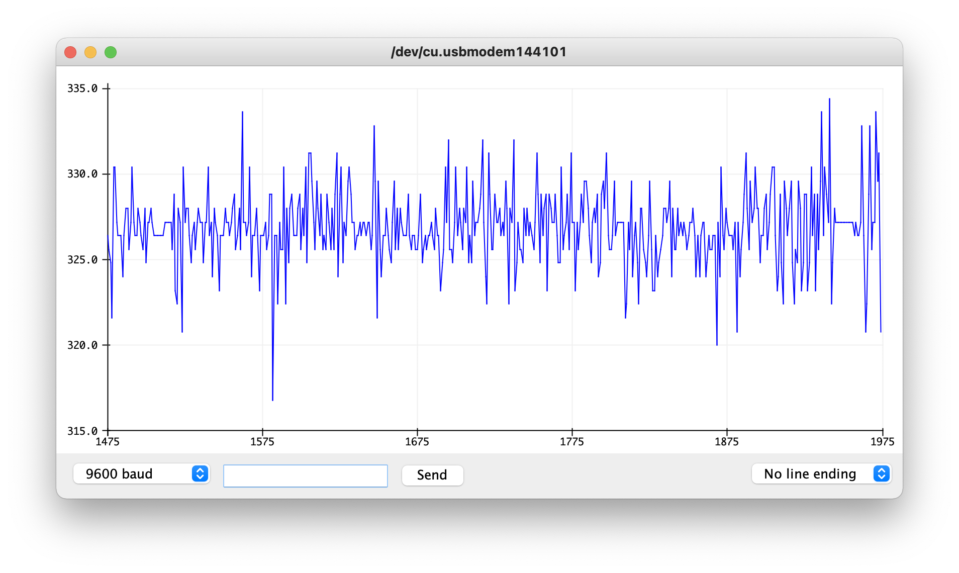
The idea for this sensor reading is to read the noise level in a room and detect whether it would be damaging to someone’s hearing. For the average human ear, a sustained noise level over 70dB or a burst of sound over 120dB can cause harm to the human ear. In order to counteract this, I used a speaker sensor connected to an Arduino to read the noise level in a room and decide whether either of these conditions have been met. If they have then an LED would turn on. So far I have gotten the speaker to read data but I haven’t been able to translate this data into decibels at the moment. The sensor I am currently using measures the noise level in its output by varying the signal to a degree relative to the amount of noise being detected. So if there is a high noise level, the sensor gives data that looks like the following:
If there is a low noise output, the data looks more uniform like a straight line.
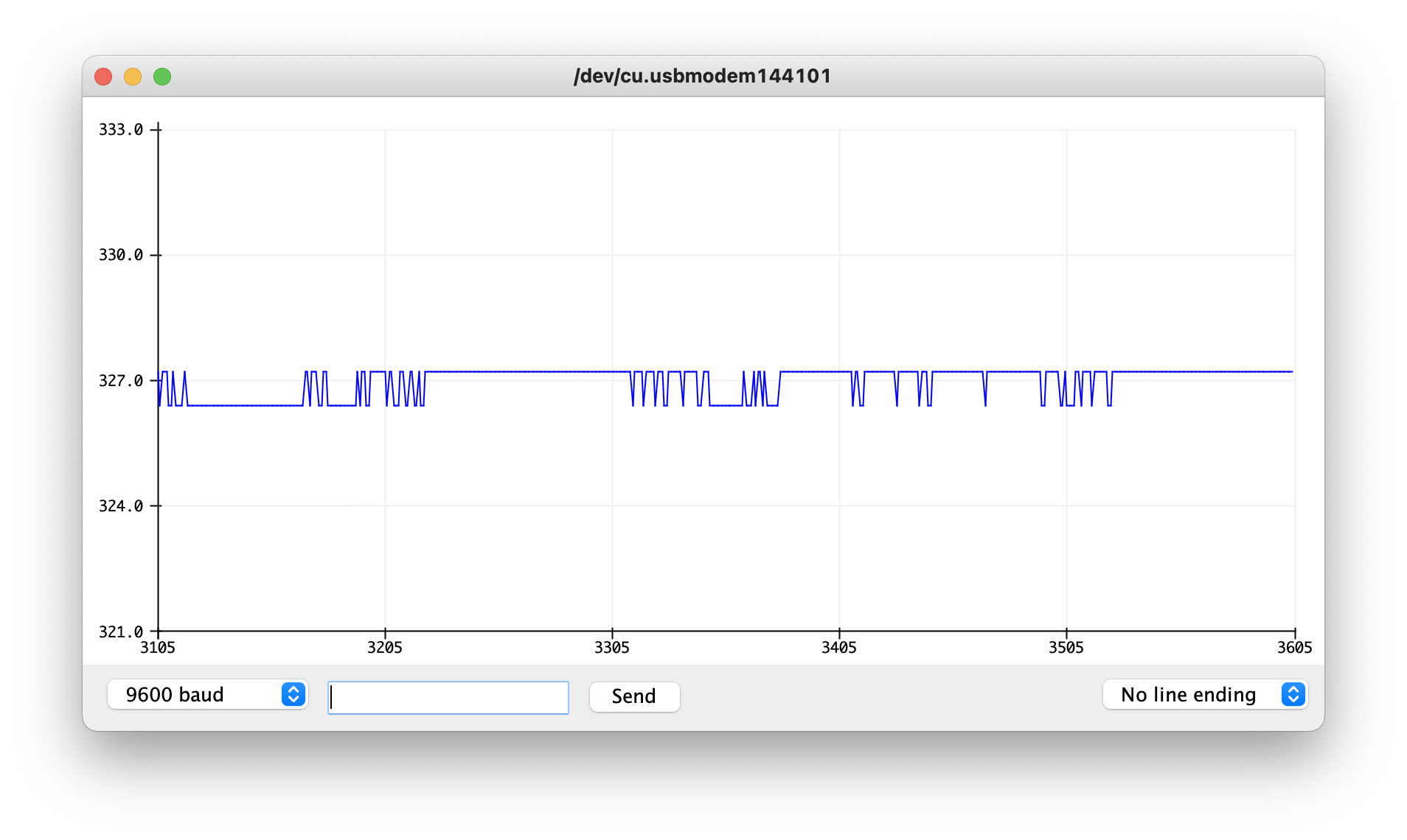
I attempted to write a script that would look at the change in this data and use a filter to smooth the delta calculation but this didn’t work very well when I tried it out. My next idea would be to take a moving average of the data over time and then take the max and min of that range as the magnitude of the noise level. With this magnitude, it could then be converted into decibels through tuning of an equation.
//Define Accelerometer Variables for pins
#define MICROPHONE   A0

double speakerLevel = 0;
double prevSpeakerLevel = 0;
double delta = 0;
double prevDelta = 0;

double alpha = 0.8;


void setup() {
  //Setup pins as inputs

  pinMode(MICROPHONE, INPUT);

  Serial.begin(9600);

}

void loop() {

  speakerLevel = analogRead(MICROPHONE);
  delta = abs(speakerLevel - prevSpeakerLevel);

  speakerLevel = alpha*speakerLevel + (1-alpha)*prevSpeakerLevel;

  delta = alpha*delta + (1-alpha)*prevDelta;

  prevDelta = delta;

  Serial.println(speakerLevel);
//  Serial.println(delta);

}
Making An Open Window More Accessible
Making An Open Window More Accessible
Description:
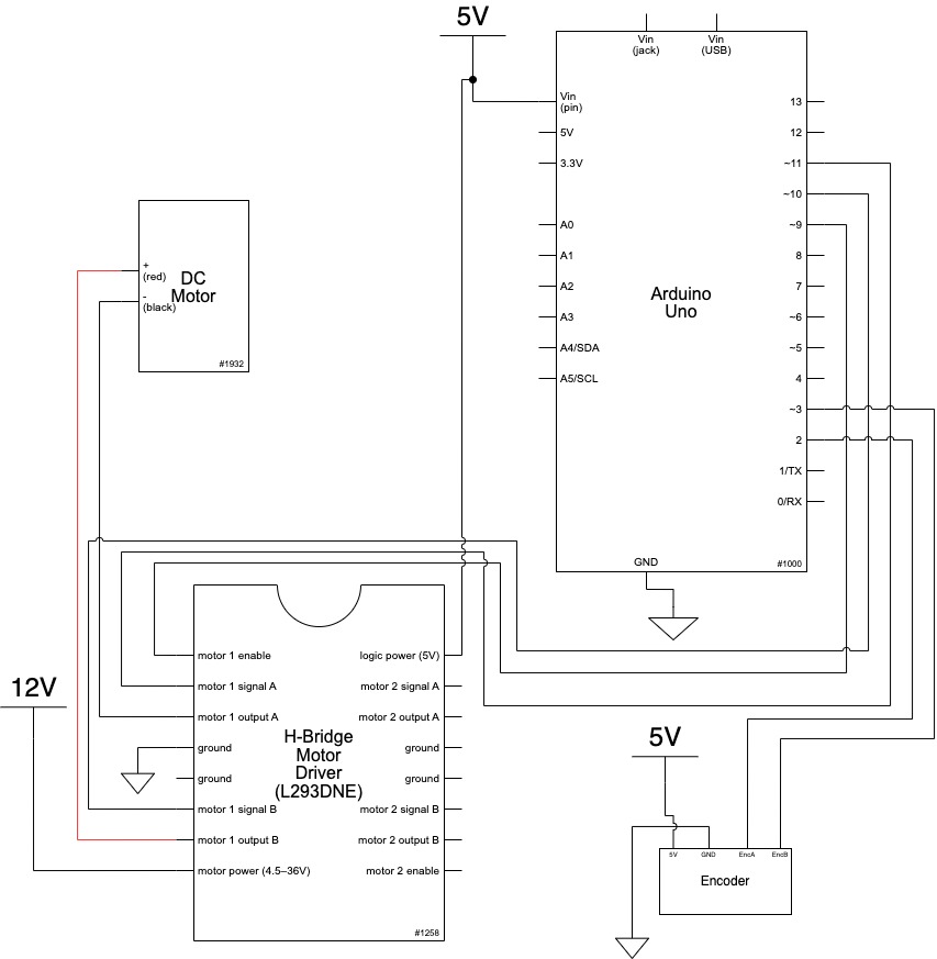
The idea behind these two sketches is to have the ability to open a window via a slider on some interface. In place of a fully working window opening mechanism is a motor with an encoder wired up to an Arduino. This Arduino then uses serial communication to relay its current position back to a p5.js sketch and retrieve its goal position from that sketch as well. The goal position is determined by an on screen slider that moves around then the user clicks and drags the slider.
While I was able to get the motor moving to a specific degree based off of serial input through the Arduino serial command, I was not able to get the p5 sketch to communicate in such a way that the Arduino could read it and then interpret it into an actionable item. I was also not able to send data from the Arduino to the p5 sketch but instead was only able to communicate with the p5 serial application shown in the demo below. Despite all this non-functional code, however, I was able to code a working slider into the p5 sketch and convert the x position of the slider into a percent of 100 as it is dragged across the screen.
Demo:
Schematic:
Code:
*
  Making Things Interactive
  Assignment 4
  Judson Kyle (judsonk)
  02/07/2022

  Collaboration and sources:
  - Encoder_Interrupts functions copied from 24-354 Gadgetry lab code

*/

// Pin Variables

#define encoderPinA   2
#define encoderPinB   3
#define motorPin1     10
#define motorPin2     11
#define motorPWM      9

int encoderCount = 12 * 98; //12 encoder counts per revolution with 1:98 gear ratio
int incomingByte = 0;

// https://www.pololu.com/product/4824
float gearRatio = (22.0*20.0*22.0*22.0*23.0)/(12.0*12.0*10.0*10.0*10.0);

bool motorSpinning = false;

// Motor distance measuring variables
volatile long currentEncoder_pos_f = 0, prevEncoder_pos = 0, revs = 0;
float motorCurPos = 0;

//PID Variables
float ep = 0; //Proportional error
float ei = 0; //Integral error
float ed = 0; //Derivative error
float prev_ep = 0;
double curTime = 0;
double prevTime = 0;

int pwmCmd = 0;

float motorGoalPos = 0; // desired angle [radians]
float kp = 50; // P gain
float ki = 0; // I gain
float kd = 0; // D gain

void setup() {

  //Initialize serial communication:
  Serial.begin(9600);

  //Initialize motor control pins
  pinMode(motorPin1, OUTPUT);
  pinMode(motorPin2, OUTPUT);
  pinMode(motorPWM, OUTPUT);

  //Initialize interrupts
  attachInterrupt(digitalPinToInterrupt(encoderPinA), encoderA, CHANGE);
  attachInterrupt(digitalPinToInterrupt(encoderPinB), encoderB, CHANGE);
}

void loop() {
  if (Serial.available() > 0){
    incomingByte = Serial.parseInt();
    if (incomingByte > 0 && incomingByte != motorGoalPos) {
       motorGoalPos = (float)incomingByte/100;
    }
  }

  //Update motorActualPos variable to reflect actual motor position in radians
  motorCurPos = (((float) currentEncoder_pos_f) / (4 * ((float) encoderCount))) * 3.14159*gearRatio/8; // Convert encoder counts to distance travelled

  Serial.println(motorCurPos);
  //PID controller to get motor to position
  // ----------------------- CONTROLLER CODE --------------
  // PID Controller
  curTime = millis();
  ep = (motorGoalPos - motorCurPos); // error in position (p)
  ei = ei + ep; // integral error in position (i)
  ed = (ep - prev_ep) / (curTime - prevTime); // derivative error in position (d)

  prev_ep = ep;
  prevTime = curTime;

  pwmCmd = (ep*kp + ei*ki + ed*kd);

  // switch directions if pass set point
  if(ep < 0) {
    // Turn on motor A & B
    digitalWrite(motorPin1, LOW);
    digitalWrite(motorPin2, HIGH);
  }
  else {
    // Turn on motor A & B
    digitalWrite(motorPin1, HIGH);
    digitalWrite(motorPin2, LOW);
  }

  pwmCmd = abs(pwmCmd);
  if (pwmCmd > 255) {
    pwmCmd = 255;
  }
  analogWrite(motorPWM, pwmCmd);

//  Serial.print("Motor Position: ");
  //Serial.println(motorCurPos, 7);
}

void encoderA(){
  // look for a low-to-high on channel A
  if (digitalRead(encoderPinA) == HIGH) {
    // check channel B to see which way encoder is turning
    if (digitalRead(encoderPinB) == LOW) {

        currentEncoder_pos_f = currentEncoder_pos_f + 1;         // CW
    }
    else {
        currentEncoder_pos_f = currentEncoder_pos_f - 1;        // CCW
    }
  }
  else   // must be a high-to-low edge on channel A
  {
    // check channel B to see which way encoder is turning
    if (digitalRead(encoderPinB) == HIGH) {

        currentEncoder_pos_f = currentEncoder_pos_f + 1;          // CW
    }
    else {
        currentEncoder_pos_f = currentEncoder_pos_f - 1;          // CCW
    }
  }
}

void encoderB(){

  // look for a low-to-high on channel B
  if (digitalRead(encoderPinB) == HIGH) {
   // check channel A to see which way encoder is turning
    if (digitalRead(encoderPinA) == HIGH) {

        currentEncoder_pos_f = currentEncoder_pos_f + 1;         // CW
    }
    else {
        currentEncoder_pos_f = currentEncoder_pos_f - 1;         // CCW
    }
  }
  // Look for a high-to-low on channel B
  else {
    // check channel B to see which way encoder is turning
    if (digitalRead(encoderPinA) == LOW) {
        currentEncoder_pos_f = currentEncoder_pos_f + 1;          // CW
    }
    else {
        currentEncoder_pos_f = currentEncoder_pos_f - 1;         // CCW
    }
  }
}
var serial;   // variable to hold an instance of the serialport library

// for macos and *nix, you'll do something like this:
//var portName = '/dev/cu.usbserial-DN01DW79';    // fill in your serial port name here

// for windows, just the COM port you're using
var portName = '/dev/tty.usbmodem144101';

var inData;   // variable to hold the input data from Arduino

var minWidth = 600;   //set min width and height for canvas
var minHeight = 400;
var width, height;    // actual width and height for the sketch
var squareWidth = 100;

var sliderLength = 200;
var sliderHeight = 100;
var sliderBackgroundStrokeWeight = 4;
var sliderBackgroundSideOffset = 100;
var sliderOffset = sliderBackgroundSideOffset + (sliderBackgroundStrokeWeight + sliderLength)/2;
var sliderX = sliderBackgroundSideOffset + sliderBackgroundStrokeWeight + sliderLength/2;
var sliderY;
var collision = false;
var windowActualPos = 0;
var windowGoalPos = 0;

var i = 0;

function setup() {
  // set the canvas to match the window size
  if (window.innerWidth > minWidth){
    width = window.innerWidth;
  } else {
    width = minWidth;
  }
  if (window.innerHeight > minHeight) {
    height = window.innerHeight;
  } else {
    height = minHeight;
  }

  sliderX = sliderOffset + sliderLength/2;
  sliderY = height/2;

  //set up canvas
  createCanvas(width, height);
  noStroke();

  //set up communication port
  serial = new p5.SerialPort();       // make a new instance of the serialport library
  serial.on('list', printList);  // set a callback function for the serialport list event
  serial.on('connected', serverConnected); // callback for connecting to the server
  serial.on('open', portOpen);        // callback for the port opening
  serial.on('data', serialEvent);     // callback for when new data arrives
  serial.on('error', serialError);    // callback for errors
  serial.on('close', portClose);      // callback for the port closing

  serial.list();                      // list the serial ports
  serial.open(portName);              // open a serial port
}

function draw() {
  drawBackgroundCanvas();

  //Draw slider background
  strokeWeight(sliderBackgroundStrokeWeight);
  stroke('grey');
  fill('white');
  rect(sliderBackgroundSideOffset, sliderY/2 - sliderHeight/2 - sliderBackgroundStrokeWeight, width - 2*sliderBackgroundSideOffset, sliderHeight + 2*sliderBackgroundStrokeWeight);

  //Draw actual slider
  strokeWeight(4);
  stroke('black');
  fill('grey');
  rect(sliderX - sliderLength/2, sliderY/2 - sliderHeight/2, sliderLength, sliderHeight);
}

//Initialize drawing canvas
function drawBackgroundCanvas() {
  // set background to black
  background(0);
    fill(255);
  textSize(30);
  textAlign(CENTER);
  text("Window Opener", width/2, 80);
  textSize(16);
  text("Degree open: " + Number(serial.read()), width/2, 100);    // displaying the input

  //Draw playing canvas
  strokeWeight(4);
  stroke('white');
  fill('black');
  noStroke();
}

function updateSliderPosition() {
  if (mouseX <= sliderOffset) {
    sliderX = sliderOffset;
  }
  else if (mouseX >= width - sliderOffset) {
    sliderX = width - sliderOffset;
  }
  else {
    sliderX = mouseX;
  }
  windowGoalPos = (sliderX - sliderOffset)/(width - 2*sliderOffset);
  windowGoalPos = (windowGoalPos);
  serial.write(windowGoalPos);
}

// Following functions print the serial communication status to the console for debugging purposes

function printList(portList) {
 // portList is an array of serial port names
 for (var i = 0; i < portList.length; i++) {
 // Display the list the console:
 print(i + " " + portList[i]);
 }
}

function mousePressed() {
  updateSliderPosition();
}

function mouseDragged() {
  updateSliderPosition();
}

function serverConnected() {
  print('connected to server.');
}

function portOpen() {
  print('the serial port opened.')
}

function serialEvent() {
    // on the arduino we are using Serial.write to send an integer
    // so we have to use Number() to convert it to a number.
    // otherwise it would be a string
    inData = Number(serial.read());
    motorActualPos = inData;
    //  if you do this, the inData value will be a string, not a number
    //
    //inData = serial.read();
    //
    // in arduino terms it's
    // int inData = 1;
    // vs
    // String inData = "1';
}

function serialError(err) {
  print('Something went wrong with the serial port. ' + err);
}

function portClose() {
  print('The serial port closed.');
}
Messing Around With Interrupts
Messing Around With Interrupts:
Functionality:
There are two different states that the system can be put into. These states are controlled by an interrupt connected to the switch. When the switch is high, the system goes into adjustment mode where the user can use the potentiometer to adjust the brightness of the LED. This adjustment is only possible while in this state. When the switch is low, the system returns to its normal state where there is a blinking mode and solid mode. These modes are controlled by a second interrupt tied to the button. While in the blinking state, the LED’s flash individually for 0.5s each in a sequence of red to yellow to green and back to red. In the solid state, all of the LED’s remain on. The brightness of the LED’s in this mode is also the same as that set in the previous adjustment state.
Code:
/*  Interrupt Assignment
 *  Judson Kyle
 *  judsonk
 *  01/31/2021
*/
#define POT_PIN     A0
#define SWITCH      3
#define BUTTON      2

#define RED_LED     11
#define YELLOW_LED  10
#define GREEN_LED   9

#define RED     0
#define YELLOW  1
#define GREEN   2

volatile bool ADJUST_STATE = false;
volatile bool BLINK = false;

int potVal = 0;
double ledBrightness;

int currentLED = 0;

int waitTime = 500; //ms
long long startTime;

int buttonDebounceTime = 300;
long long buttonDebounceStart = 0;
volatile bool BUTTON_DEBOUNCE = false;
bool BUTTON_PREV_DEBOUNCE = false;


void setup() {

  pinMode(POT_PIN, INPUT);
  pinMode(SWITCH, INPUT);

  //Interrupts
  attachInterrupt(digitalPinToInterrupt(BUTTON), handleButton, RISING);

  //LED's
  pinMode(RED_LED, OUTPUT);
  pinMode(YELLOW_LED, OUTPUT);
  pinMode(GREEN_LED, OUTPUT);

  Serial.begin(9600);

}

void handleButton() {
  if (!BUTTON_DEBOUNCE) {
    BUTTON_DEBOUNCE = true;
    BLINK = !BLINK;
  }
}

void loop() {

  //Read switch state
  ADJUST_STATE = digitalRead(SWITCH);
  Serial.println(ADJUST_STATE);

//  Serial.print("DEBOUNCE: \t");
//  Serial.print(DEBOUNCE);
//
//  Serial.print("\tdebounceStart: \t");
//  Serial.print((int)debounceStart);
//
//  Serial.print("\tTime Elapsed: \t");
//  Serial.println(millis() - (int)debounceStart);

  //Process switch logic
  if (ADJUST_STATE) {
    potVal = analogRead(POT_PIN);
    ledBrightness = (256*potVal)/1024;
    analogWrite(RED_LED, (int)ledBrightness);
    analogWrite(YELLOW_LED, (int)ledBrightness);
    analogWrite(GREEN_LED, (int)ledBrightness);
  }

  //Change brightness of LED based off potentiometer switch when not in blink mode
  if (BLINK) {
    if (millis() - startTime > waitTime) {
      startTime = millis();
      currentLED++;
      if (currentLED >= 3) {
        currentLED = 0;
      }
    }

    switch(currentLED) {
      case RED:
        analogWrite(RED_LED, (int)ledBrightness);
        analogWrite(YELLOW_LED, LOW);
        analogWrite(GREEN_LED, LOW);
        break;
      case YELLOW:
        analogWrite(RED_LED, LOW);
        analogWrite(YELLOW_LED, (int)ledBrightness);
        analogWrite(GREEN_LED, LOW);
        break;
      case GREEN:
        analogWrite(RED_LED, LOW);
        analogWrite(YELLOW_LED, LOW);
        analogWrite(GREEN_LED, (int)ledBrightness);
        break;
      default:
        break;
    }
  }
  else {  //If not in blinking mode make all LED's light up
    analogWrite(RED_LED, (int)ledBrightness);
    analogWrite(YELLOW_LED, (int)ledBrightness);
    analogWrite(GREEN_LED, (int)ledBrightness);
  }

  //Handle button debounce
  if (BUTTON_DEBOUNCE && !BUTTON_PREV_DEBOUNCE) {
    buttonDebounceStart = millis();
  }
  if (abs(buttonDebounceStart - millis()) > buttonDebounceTime) {
    BUTTON_DEBOUNCE = false;
  }
  BUTTON_PREV_DEBOUNCE = BUTTON_DEBOUNCE;
}
Images:
Assignment 2 – Judson Kyle
Thinking About the Future:
One way that people thought about the future in the past brought up in “Make It So” is by connecting it to what already exists. The first two chapters have many examples of this, but one of the most notable is the connection between science fiction and the future. In the past, science fiction has been used as a starting point for futuristic designs because the genre cements certain expectations and ideas in the general public of how things should look. The popularity of science fiction causes people to be more comfortable with the new technology and ideas proposed. As mentioned in the reading, people this comfort results in a certain expectation of how things should look which in turn drives how people think about design problems. Another example of this looking for comfort can be found in how people dreamed about and pursued space travel. Similar to how ships and the sea were seen as the new way of the future a while ago, space was beginning to emerge as this new frontier. Since people already had an association between nautical references and exploring the unknown, this became a large inspiration for things like the word astronaut or the way space ships were designed. Both of these examples from the reading demonstrate the search for familiarity in designing for the future which resulted in expansion of what already existed.
In addition to this expansion on the present, people also thought about the future as having to do with interaction of some sort. As mentioned throughout the reading, the future consisted of products that had to have human interaction of some sort in order to function requiring some sort of interface to work. As mentioned previously, the connection between design and science fiction is also important here because a lot of science fiction has to do with how people interact with futuristic devices.
Interrupts In Daily Life – Judson Kyle
Some Examples of Interrupts:
As a diver, when I am learning a new dive, the coach will yell at us while we are in the air and upon hearing the call we will come out ready to enter the water. Another interrupt is when you have the urge to use the restroom, especially during the night. An example of a less common interrupt would be a fire alarm for a fire drill or actual fire emergency.
Assignment 1 – Judson Kyle
Assignment 1 – Judson Kyle
Design for Dreaming:
One of the biggest differences between “Design for Dreaming” and contemporary media like the MCU or Bladerunner is the focus on travel and scope. While both have a sense of being able to travel wherever we want much easier than is possible at the current moment, more contemporary media has a large focus on space travel and exploring the unknown universe whereas “Design for Dreaming” is focused more on travel on Earth via the automobile. Another key difference is the focus on agency. In “Design for Dreaming” the main character is shown repeatedly using futuristic products for her own gain pressing a button and having a cake made or simply thinking about having binoculars and having them appear. This type of futuristic technology is portrayed as something that normal people can acquire starkly contrasting that of the MCU. The technology in the MCU is much more out of reach only accessible to the heroes possessing the money or power to wield it.
Useful Interaction:
The Idea:
As you can see from the comic below, waking up to an alarm in the morning is already very difficult let alone trying to adjust to the sudden brightness of a lamp.
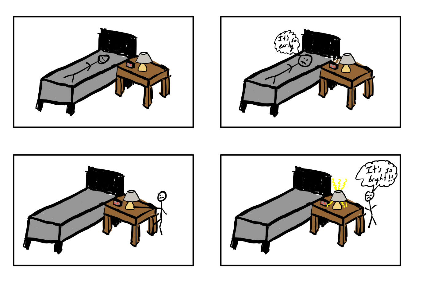
While this problem could easily be solved with an adjustable light level on the lamp switch, why not take it one step further and create an artificial sunrise by slowly brightening the lamp in anticipation of the alarm. This project utilizes this concept by incorporating both the adjustable slider and the artificial sunrise into one item. This not only helps adjust the user to the light levels but also helps them wake up in a more natural and gradual way.
Proof of Concept:
This project can easily be achieved with a lamp, an electronically controlled potentiometer, a linear motion potentiometer, a power supply, and some voltage regulators connected to an Arduino.