When running a MATLAB script, there are a few things that trigger a sound to go off. The first of these is when a break in the code is set for debugging which for a while triggered a nice sounding double beat almost like a wooden percussion instrument. The second is when an error happens in the code and it stops running as a result invoking the same noise. While the first use case is very informative, the second case is not so. Recently, my perspective on these sounds changed as I listened to another friends computer make a screaming sound as the program encounters an error. This slight change in the error noise changed my whole perspective on what was happening in the script.
Category: Uncategorized
Reading Assignment: Make It So, 3/17
Reading assignment: Chapters 6 and 10 Of Make it So
Chapter 6: Sonic Interfaces
The authors establish 2 major categories for sonic interfaces: sonic output and voice interfaces. The chapter covers outputs including considerations for effects such as alarms, ambient sound such as buzzing or clattering made by machinery, and directional sound. Topics around interfaces deal with music and multiple types of voice interfaces, including more sophisticated conversational interfaces. I agree that the more sophisticated the voice interface, the more that is expected out of it (for example, when dealing with the automated voice when calling insurance or the bank). Still, I’m surprised that there still is not a feature that allows automated systems to measure how annoyed a person is getting with the system (for example, syllables becoming more terse, or volume increasing) and getting the caller over to a human associate as quickly as possible. Perhaps everyone gets terse and annoyed, so there’s no need to measure it, or rank people by the amount that the automated system annoys them.
—-
Chapter 10: Communication
I was interested to see authors using terms “asynchronous” and “synchronous,” which I’m sure have been used in discussions around communication for a long time, but I only started seeing that term at the start of COVID-19 to make a distinction between a zoom call and a zoom recording. The chapter identifies the functions needed in both categories of communication: composing, playback, activation, connecting between caller and receiver, connection monitoring, ending a call. Other considerations addressed include volume control, accompanying visuals/video, mute functions, language translation, and disguises. One of the noted opportunities- subtle appearance alteration (lighting correction, blurred background, etc)- is realized today with features on Zoom.
One of the subjects addresses is the complexities of language translation- it reminded me of an article I read about the challenges of translating Twenty Fragments of a Ravenous Youth, written in Chinese by Xiaolu Guo. The author describes the language of the book as “slangy, raw Chinese” and the article discussed the difficulties of conveying that tone and the cultural connotations associated with it into English. By comparison, machines attempting to translate in real time would be at an even greater disadvantage. Perhaps the translate-in-real-time would be forced to restrict itself to austere and utilitarian function, or risk completely missing the boat.
Crit 1 (Using the outdoors for heating/cooling) – Jud
Idea:
The main idea behind this project is to open the window to cool or heat your room when the outside temperature is what you want your room temperature to be. For example, in the summer, if it is a super nice day out and your room is very hot, you could enter a temperature into the system and it would automatically open the window to let outside air in to adjust the room temperature. This also has a dual purpose in the winter for if your house is too hot and the system could open the window to let a cool breeze in.
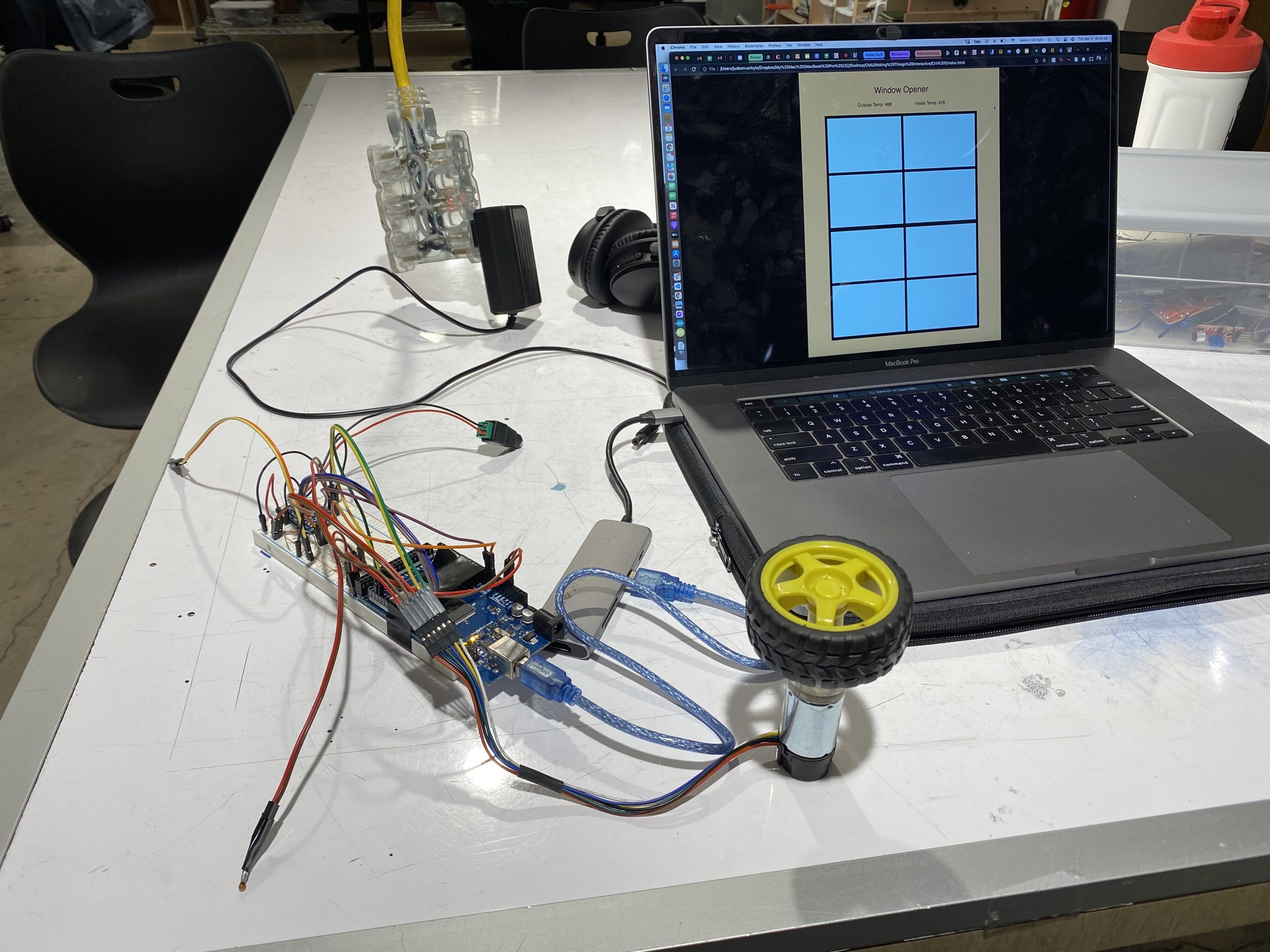
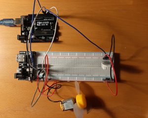
The main components of this system are two thermistors for measuring outside and inside temperature, a motor with an encoder to actuate the window, a motor driver to control the speed of the motor, and a p5 script animating the information from the Arduino in a helpful way. The Arduino sends the data over serial communication to the p5 script which then displays this information to the user and animates the virtual window corresponding to the current motor position.
As shown in the demo video below, the system works very well detecting a need for opening the window and acting upon it. In addition, the p5 script very accurately shows the degree of openness of the window. While these component work very well together, the controller is still fairly simple. Currently, there is just one setting for open and closed meaning the window doesn’t open a certain degree based off the temperature difference between the room and the goal temp. With more time this feature could be implemented, but for demonstration purposes of this concept, the current controller works well.
Images:
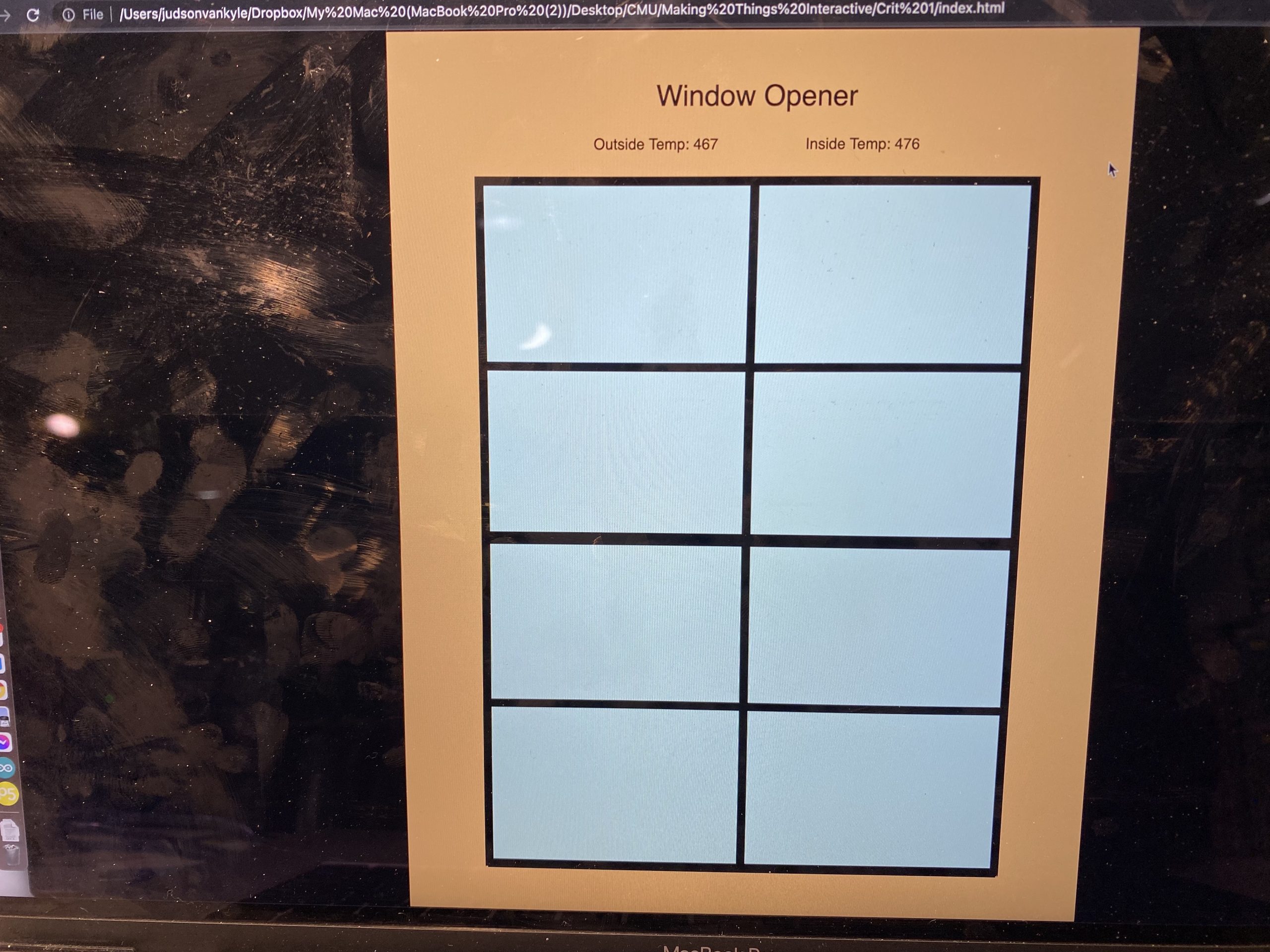
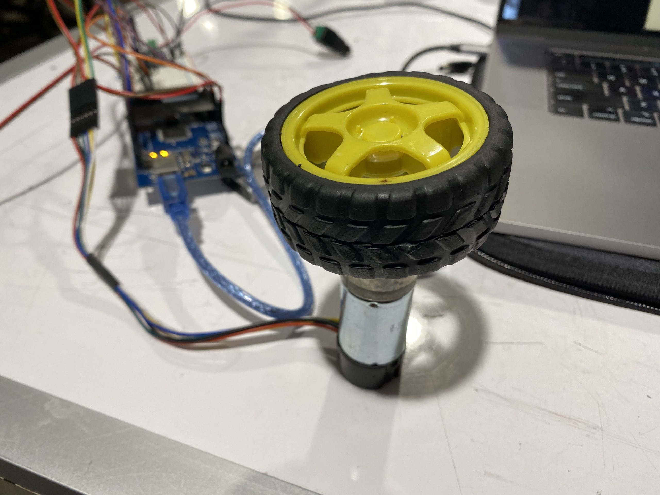
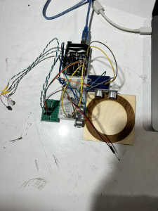
Here are images of the final system concept. The first image is an overall image showing both the physical build and the virtual animation. The second image is a close up of the virtual animation screen showing the displayed outside and inside temperatures as well as the window itself. Finally, the third image shows a top view of the physical wiring for the system.
Videos:
Video demonstration of the motor position feedback controlling the amount the virtual window is open.
Here is a video of the full system demo. As shown, when the outside temperature rises above the inside temperature, the window opens. When the outside temperature falls below the inside temperature, the window closes.
Code:
P5.js
let serial;
let latestData = "waiting for data";
var outData;

var minWidth = 600;   //set min width and height for canvas
var minHeight = 400;
var width, height;    // actual width and height for the sketch
var squareWidth = 100;

var OuterWindowHeight = 800;
var OuterWindowLength = 600;

var InnerWindowHeight = OuterWindowHeight/2;
var InnerWindowLength = OuterWindowLength;

var panelThickness = 10;
var RoomLength = 800;

var bottomInnerWindowY;
var y = 0;

var roomColor = '#f7c07c';
var skyColor = '#c2f9ff';

var outsideTemp = 100;
var insideTemp = 100;

var prevString;


function setup() {
 // set the canvas to match the window size
 if (window.innerWidth > minWidth){
  width = window.innerWidth;
  } else {
    width = minWidth;
  }
  if (window.innerHeight > minHeight) {
    height = window.innerHeight;
  } else {
    height = minHeight;
  }

  bottomInnerWindowY = (height - OuterWindowHeight)/2 + 50 + OuterWindowHeight - InnerWindowHeight/2;

  //set up canvas
  createCanvas(width, height);
  noStroke();

 serial = new p5.SerialPort();

 serial.list();
 serial.open('/dev/tty.usbmodem144101');

 serial.on('connected', serverConnected);

 serial.on('list', gotList);

 serial.on('data', gotData);

 serial.on('error', gotError);

 serial.on('open', gotOpen);

 serial.on('close', gotClose);
}

function serverConnected() {
 print("Connected to Server");
}

function gotList(thelist) {
 print("List of Serial Ports:");

 for (let i = 0; i < thelist.length; i++) {
  print(i + " " + thelist[i]);
 }
}

function gotOpen() {
 print("Serial Port is Open");
}

function gotClose(){
 print("Serial Port is Closed");
 latestData = "Serial Port is Closed";
}

function gotError(theerror) {
 print(theerror);
}

function gotData() {
  let currentString = serial.readLine();
  trim(currentString);
  if (!currentString) return;
  console.log(currentString);
  // latestData = currentString;
  // currentString = Number(currentString) - 10000;
  if ((Number(currentString) - 10000) < 10000) {
    insideTemp = (Number(currentString) - 10000);
    return;
  }
  else if ((Number(currentString) - 20000) < 10000) {
    outsideTemp = (Number(currentString) - 20000);
    return;
  }
  else if ((Number(currentString) - 30000) < 10000) {
    y = (Number(currentString) - 30000)/1000;
    return;
  }
}

function draw() {

  var outerWindowBottomY = (height - OuterWindowHeight)/2 + 50;
  var topInnerWindowY = outerWindowBottomY + InnerWindowHeight/2;

  //Update bottom window position
  bottomInnerWindowY = (height - OuterWindowHeight)/2 + 50 + OuterWindowHeight - InnerWindowHeight/2 - (y/3.1415)*(OuterWindowHeight - InnerWindowHeight);

  background(0);

  //Draw canvas
  strokeWeight(4);
  stroke('white');
  fill('black');
  noStroke();

  // //Draw Room
  strokeWeight(4);
  stroke('black');
  fill(roomColor);
  rect((width - RoomLength)/2, 0, RoomLength, height);

  fill('black');
  stroke(roomColor);
  textSize(30);
  textAlign(CENTER);
  text("Window Opener", width/2, 80);
  textSize(16);
  text("Outside Temp: " + outsideTemp + "\t\t\t\t\t\t\t\t\t\t Inside Temp: " + insideTemp, width/2, 125);    // displaying the input

  //Draw outer window
  strokeWeight(4);
  stroke('black');
  fill(skyColor);
  rect((width - OuterWindowLength)/2, outerWindowBottomY, OuterWindowLength, OuterWindowHeight);

  //Draw top inner window
  strokeWeight(4);
  stroke('black');
  strokeWeight(10);
  noFill();
  rect((width - InnerWindowLength)/2, topInnerWindowY - InnerWindowHeight/2, InnerWindowLength, InnerWindowHeight);
  strokeWeight(10);
  line((width - InnerWindowLength)/2, topInnerWindowY, (width - InnerWindowLength)/2 + InnerWindowLength, topInnerWindowY);//y line
  line(width/2, outerWindowBottomY, width/2, outerWindowBottomY + InnerWindowHeight);//x line

  //Draw bottom inner window
  strokeWeight(4);
  stroke('black');
  strokeWeight(10);
  noFill();
  rect((width - InnerWindowLength)/2, bottomInnerWindowY - InnerWindowHeight/2, InnerWindowLength, InnerWindowHeight);
  strokeWeight(10);
  line((width - InnerWindowLength)/2, bottomInnerWindowY, (width - InnerWindowLength)/2 + InnerWindowLength, bottomInnerWindowY);//y line
  line(width/2, bottomInnerWindowY - InnerWindowHeight/2, width/2, bottomInnerWindowY + InnerWindowHeight/2);//x line

}


function mousePressed() {

}

function mouseDragged() {

}
Arduino
/*
 * Window Climate Controller
 * Judson Kyle
 * judsonk
 *
 * Collaboration:
 *  - Used thermistor code from this site: https://www.circuitbasics.com/arduino-thermistor-temperature-sensor-tutorial/
 *
 */

#define THERMISTOR1_PIN   A0
#define THERMISTOR2_PIN   A1
#define encoderPinA   18
#define encoderPinB   19
#define motorPin1     10
#define motorPin2     11
#define motorPWM      9

#define P_I 3.14159

int encoderCountRev = 48; //48 encoder counts per revolution
int incomingByte = 0;

// https://www.pololu.com/product/4824
float gearRatio = 2*(22.0*20.0*22.0*22.0*23.0)/(12.0*12.0*10.0*10.0*10.0);

bool motorSpinning = false;

// Motor distance measuring variables
volatile long currentEncoder_pos_f = 0, prevEncoder_pos = 0, revs = 0;
float motorCurPos = 0;

//PID Variables
float ep = 0; //Proportional error
float ei = 0; //Integral error
float ed = 0; //Derivative error
float prev_ep = 0;
double curTime = 0;
double prevTime = 0;

int pwmCommand = 0;

float kp = 50; // P gain
float ki = 0; // I gain
float kd = 0; // D gain
float motorGoalPos = P_I; // desired angle [radians]

float temp1, temp2;
float goalTemp = 480; //Degrees F

float insideOutsideDiff = 0;
float insideGoalDiff = 0;

float windowOpeningLength = P_I; //radians at the moment
float maxDiff = 100;

void setup() {
  //Initialize motor control pins
  pinMode(motorPin1, OUTPUT);
  pinMode(motorPin2, OUTPUT);
  pinMode(motorPWM, OUTPUT);

  //Initialize interrupts
  attachInterrupt(digitalPinToInterrupt(encoderPinA), encoderA, CHANGE);
  attachInterrupt(digitalPinToInterrupt(encoderPinB), encoderB, CHANGE);

  Serial.begin(9600);
}

void loop() {

  //Update motor current position
  motorCurPos = (2*P_I*currentEncoder_pos_f) / (gearRatio*encoderCountRev);

  temp1 = readTemp('v', THERMISTOR1_PIN);
  temp2 = readTemp('v', THERMISTOR2_PIN);

  insideOutsideDiff = temp1 - temp2; //Add in conditionals for if temperature difference is negative
  insideGoalDiff = temp1 - goalTemp; //Add in conditionals for if temperature difference is negative

  //Update motor goal position based off of difference in temperature
  if (insideGoalDiff < 0) { //Goal temp is higher than inside temp
    if (insideOutsideDiff < 0) { //Outside temp higher than inside temp
//      int openDistance = abs(insideGoalDiff/maxDiff)*windowOpeningLength;
      motorGoalPos = P_I;
    }
    else { //Ouside temp lower than or equal to inside temp
      motorGoalPos = 0;
    }
  }
  else if (insideGoalDiff > 0) { //Goal temp lower than inside temp
    if (insideOutsideDiff > 0) { //Outside temp lower than inside temp
//      int openDistance = (insideGoalDiff/maxDiff)*windowOpeningLength;
      motorGoalPos = P_I;
    }
    else { //Ouside temp higher than or equal to inside temp
      motorGoalPos = 0;
    }
  }

  updateMotorCmd(updatePID(motorGoalPos, motorCurPos));

  //Send data to p5 script for visualization
  sendData();
}

float readTemp(char degreeType, int ThermistorPin) {
  float logR2, R2, T;
  float c1 = 1.009249522e-03, c2 = 2.378405444e-04, c3 = 2.019202697e-07;

  int R1 = 1000;

  int Vo = analogRead(ThermistorPin);
  R2 = R1 * (1023.0 / (float)Vo - 1.0);
  logR2 = log(R2);

  T = (1.0 / (c1 + c2*logR2 + c3*logR2*logR2*logR2));

  switch (degreeType){
    case 'f':
    case 'F':
      T = T - 273.15;
      T = (T * 9.0)/ 5.0 + 32.0;
      break;
    case 'c':
    case 'C':
      T = T - 273.15;
      break;
    default:
      return Vo;
      break;
  }

  return T;
}

int updatePID(float goalPos, float curPos) {
  int pwmCmd;

  // PID Controller
  curTime = millis();
  ep = (goalPos - curPos); // error in position (p)
  ei = ei + ep; // integral error in position (i)
  ed = (ep - prev_ep) / (curTime - prevTime); // derivative error in position (d)

  prev_ep = ep;
  prevTime = curTime;

  pwmCmd = (ep*kp + ei*ki + ed*kd);

  return pwmCmd;
}

void sendData() {
  int temp1Send = 10000 + temp1;
  Serial.println(temp1Send); //Inside temp
  int temp2Send = 20000 + temp2;
  Serial.println(temp2Send); //Outside temp
  int sendData = 30000 + (int) (motorCurPos*1000);
  Serial.println(sendData); //Wnidow Opening
}

void updateMotorCmd(int pwmCmd) {
  // switch directions if pass set point
  if(ep < 0) {
    // Turn on motor A & B
    digitalWrite(motorPin1, LOW);
    digitalWrite(motorPin2, HIGH);
  }
  else {
    // Turn on motor A & B
    digitalWrite(motorPin1, HIGH);
    digitalWrite(motorPin2, LOW);
  }

  pwmCmd = abs(pwmCmd);
  if (pwmCmd > 255) {
    pwmCmd = 255;
  }
  analogWrite(motorPWM, pwmCmd);
}

void encoderA(){
  // look for a low-to-high on channel A
  if (digitalRead(encoderPinA) == HIGH) {
    // check channel B to see which way encoder is turning
    if (digitalRead(encoderPinB) == LOW) {

        currentEncoder_pos_f = currentEncoder_pos_f + 1;         // CW
    }
    else {
        currentEncoder_pos_f = currentEncoder_pos_f - 1;        // CCW
    }
  }
  else   // must be a high-to-low edge on channel A
  {
    // check channel B to see which way encoder is turning
    if (digitalRead(encoderPinB) == HIGH) {

        currentEncoder_pos_f = currentEncoder_pos_f + 1;          // CW
    }
    else {
        currentEncoder_pos_f = currentEncoder_pos_f - 1;          // CCW
    }
  }
}

void encoderB(){

  // look for a low-to-high on channel B
  if (digitalRead(encoderPinB) == HIGH) {
   // check channel A to see which way encoder is turning
    if (digitalRead(encoderPinA) == HIGH) {

        currentEncoder_pos_f = currentEncoder_pos_f + 1;         // CW
    }
    else {
        currentEncoder_pos_f = currentEncoder_pos_f - 1;         // CCW
    }
  }
  // Look for a high-to-low on channel B
  else {
    // check channel B to see which way encoder is turning
    if (digitalRead(encoderPinA) == LOW) {
        currentEncoder_pos_f = currentEncoder_pos_f + 1;          // CW
    }
    else {
        currentEncoder_pos_f = currentEncoder_pos_f - 1;         // CCW
    }
  }
}
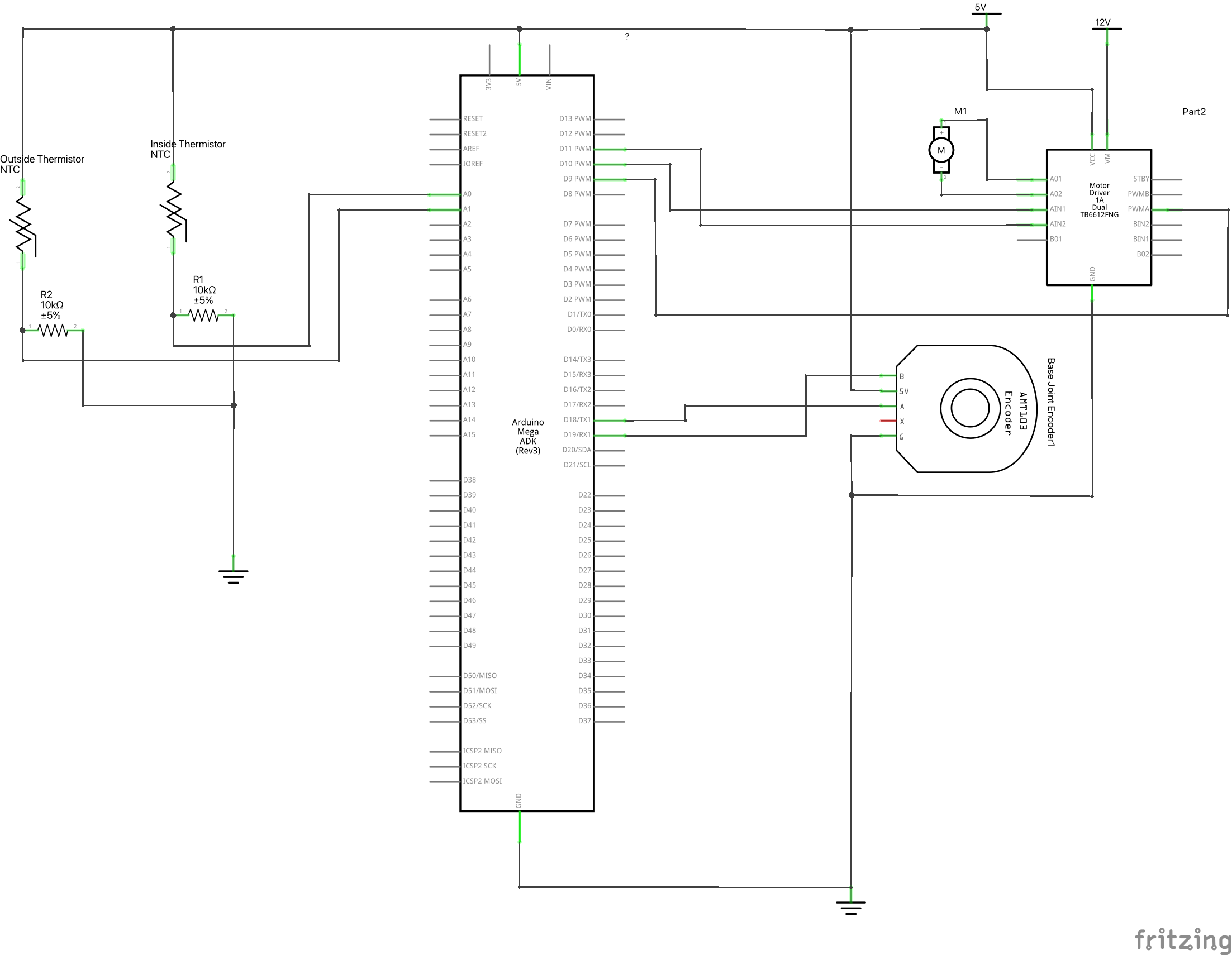
Electrical Schematic:
Kinetic Crit: Stove-top Temperature Indicator – James Kyle
Problem:
Stoves are a common household product for anyone with a kitchen and extremely useful in giving a person some autonomy over their life. However, they are by nature extremely hazardous because they deal with high temperatures. Although many electric stovetops have indication lights for when the surface is hot, these indications do nothing to help a blind user know when the stovetop is hot and not safe to touch.
Solution:
To solve this problem, I have decided to make a stove top temperature indicator that relies on sound and proximity to the stovetop to indicate when a surface is safe to touch. A set of ultrasonic rangers determines when an object is near and how far away the object is from the stove top. If the stovetop is too hot, the device then uses vibration motors to bounce around and audibly indicate the ensuing danger. The user also has an override button to turn the vibration off because the device cannot discern the difference between intentional and unintentional object placement on the hot stove.
Proof of Concept:
For a proof of concept, I have built a smaller version with one ultrasonic for each x and y components of the stove top. There are only two vibration motors as well just to show the possibility. In a real version of the concept, the vibration motors would be placed in a resonating surface such as a bell to create more noise and alert the user better.
Demo:
Code:
//Temperature stuff
const int tempSensor = A0;
float stoveTemp;
float stoveTempThreshold = 40; // [*C]
float c1 = 1.009249522e-03, c2 = 2.378405444e-04, c3 = 2.019202697e-07;


//Vibration motor stuff
const int vibrationMotor1 = 6;
const int vibrationMotor2 = 7;
const int vibrationMotorCount = 2;
int vibrationMotors[vibrationMotorCount] = {vibrationMotor1, vibrationMotor2};


//Object detection stuff
const int trigPin1 = 12;
const int echoPin1 = 13;
const int trigPin2 = 8;
const int echoPin2 = 9;
float dangerDistance = 5; //Distance threshold


//E-stop stuff
const int stopButton = 3;


//Logical stuff
bool stoveIsHot;
bool objectOnStove;
bool userOverride = false;


//Debounce Stuff
unsigned long debounceTimer = 0;
unsigned long debounceDelay = 100;
bool prevButtonState = false;
bool currButtonState = false;
bool lookForPress = true;


void setup()
{

  pinMode(trigPin1, OUTPUT); // Sets the trigPin as an Output
  pinMode(echoPin1, INPUT); // Sets the echoPin as an Input
  pinMode(trigPin2, OUTPUT); // Sets the trigPin as an Output
  pinMode(echoPin2, INPUT); // Sets the echoPin as an Input
  pinMode(tempSensor, INPUT);
  pinMode(stopButton, INPUT_PULLUP);

  pinMode(vibrationMotor1, OUTPUT);
  pinMode(vibrationMotor2, OUTPUT);

  attachInterrupt(digitalPinToInterrupt(stopButton), stopNoise, LOW);

  Serial.begin(9600); // Starts the serial communication

}

void loop()
{

  if (prevButtonState != currButtonState) {
    debounceTimer = millis();
    prevButtonState = currButtonState;
  }

  if (millis() - debounceTimer > debounceDelay) {
    lookForPress = true;
  }


  if (!userOverride) {
    stoveIsHot = checkStoveTemp();

    if (stoveIsHot) {
      objectOnStove = checkStoveSpace();
    }
  } else {
    vibrateMotors(0);
  }


}


int getDistance(int trigPin, int echoPin) {

  long duration;
  int distance;

  // Clears the trigPin
  digitalWrite(trigPin, LOW);
  delayMicroseconds(2);
  // Sets the trigPin on HIGH state for 10 micro seconds
  digitalWrite(trigPin, HIGH);
  delayMicroseconds(10);
  digitalWrite(trigPin, LOW);
  // Reads the echoPin, returns the sound wave travel time in microseconds
  duration = pulseIn(echoPin, HIGH);
  // Calculating the distance
  distance = duration * 0.034 / 2;
  // Prints the distance on the Serial Monitor
  return distance;

}


bool checkStoveTemp() {

  const int stoveTempThreshold = 40;
  static float stoveTemp;
  static bool DANGER;

  stoveTemp = analogRead(tempSensor);
  stoveTemp = log(stoveTemp);
  stoveTemp = (1.0 / (c1 + c2 * stoveTemp + c3 * stoveTemp * stoveTemp * stoveTemp));
  stoveTemp = stoveTemp - 353.15;
  //Serial.println(stoveTemp);


  if (stoveTemp > stoveTempThreshold) {
    if (!DANGER) {
      DANGER = true;
      Serial.println("WARNING...DANGER!!");
    }
  } else {
    if (DANGER) {
      DANGER = false;
      Serial.println("Surface is safe to touch now");
    }
  }

  return DANGER;
}


bool checkStoveSpace() {

  static bool moveHand = false;
  static const int numberOfDistanceSensors = 2;
  static float distanceReadings[numberOfDistanceSensors];
  static int distanceSensorPins[2 * numberOfDistanceSensors] = {trigPin1, echoPin1, trigPin2, echoPin2};


  //Check ultrasonic rangers
  for (int i = 0; i < numberOfDistanceSensors; i++) {
    int currTrig = distanceSensorPins[2 * i];
    int currEcho = distanceSensorPins[2 * i + 1];
    distanceReadings[i] = getDistance(currTrig, currEcho);
  }


  //Indicate danger if something is close to stove
  for (int i = 0; i < numberOfDistanceSensors; i++) {
    if (distanceReadings[i] < dangerDistance) {

      Serial.println("MOVE YOU HAND!!");

      //Make warning noise
      vibrateMotors(1);

      return true;

    }
  }


  //Turn off warning noise
  vibrateMotors(0);


  return false;
}

void vibrateMotors(int vibrationSpeed) {
  for (int i = 0; i < vibrationMotorCount; i++) {
    digitalWrite(vibrationMotors[i], vibrationSpeed);
  }
}


void stopNoise() {

  if (lookForPress) {
    currButtonState = !currButtonState;
    lookForPress = false;

    if (userOverride) {
      userOverride = false;
    } else {
      userOverride = true;
    }

  }

}
Crit1 Development: Experiment with Fan Motor and Light Sensor TEMT6000
With the TEMT6000 light sensor, I can turn on a motor based on input to the light sensor, similar to the one I had with the DHT-22.
With the TEMT6000, I used an analog write (instead of the digital write with the DHT-22) and the data arrives in float form. Several lines of code convert the reading into a percent. Data smoothing and millis () set up are the same as previous DHT-22 code.
#define lightPin A0 //Ambient light sensor reading

//data smoothing
const int numReadings = 5;
float ligReadings [numReadings];
int ligReadIndex = 0;
float ligTotal = 0;
float ligAverage = 0;
int inputPin = lightPin; //put sensor pin here
//detecting sensor change
int last;
//response to sensor change

//for fan and motor
int speedPin = 5;
int dir1 = 4;
int dir2 = 3;
int mSpeed = 0;
unsigned long lastReadTime = 0;

void setup() {
  // put your setup code here, to run once:
  //pins for fan and motot
  pinMode(speedPin, OUTPUT);
  pinMode(dir1, OUTPUT);
  pinMode(dir2, OUTPUT);
  pinMode(lightPin, INPUT);

  for (int thisReading = 0; thisReading < numReadings; thisReading++) {
    ligReadings[thisReading] = 0;
  }
  Serial.begin(9600);
  lastReadTime = millis();
}

void loop() {
  //delay(1000);

  if ((millis() - lastReadTime) >= 5000UL) {
    Serial.println(lastReadTime);
    Serial.println(millis());
    lastReadTime = millis();
    //light sensor read
    float light = analogRead(lightPin);
    float light_ratio = light / 1023.0;
    float light_percent = light_ratio * 100;

    ligTotal = ligTotal - ligReadings[ligReadIndex];
    ligReadings[ligReadIndex] = light_percent;
    ligTotal = ligTotal + ligReadings [ligReadIndex];
    ligReadIndex = ligReadIndex + 1;
    if (ligReadIndex >= numReadings) {
      ligReadIndex = 0;
    }
    ligAverage = ligTotal / numReadings;
    Serial.println(light_percent);
    Serial.println(ligAverage);

  }


  if (ligAverage > 25)
  {
    digitalWrite(dir1, HIGH);
    digitalWrite(dir2, LOW);
    analogWrite(speedPin, 225);
  }else
  {
    digitalWrite(dir1,HIGH);
    digitalWrite(dir2,LOW);
    analogWrite(speedPin, 0);
  }
}
Next, I plan to use the sensor to turn another motor (the stepper motor, which I think is a better fit for turning the plant turntable).
Crit1 Development: Experiment with Button and p5js
I ran into challenges with the previous DHT22 sensor to p5js assignment. I performed another test run using input from a button. With this, I was able to connect the p5.js web editor to the arduino, and have an image on the screen of the web editor change when the button input changed.
Arduino sketch below:
const int buttonPin = 2;
int buttonValue = 0;

void setup() {
  // put your setup code here, to run once:
  pinMode(buttonPin, INPUT);
  Serial.begin(9600);

}

void loop() {
  // put your main code here, to run repeatedly:
  buttonValue = digitalRead(buttonPin);
  Serial.println(buttonValue);
  delay(10);

}
p5js sketch:
let serial;
let newData = "waiting for data";

function setup() {
  createCanvas(windowWidth, windowHeight);
  serial = new p5.SerialPort();
  serial.list();
  serial.open('COM5');
  serial.on('connected', serverConnected);
  serial.on('list',gotList);
  serial.on('data',gotData);
  serial.on('error',gotError);
  serial.on('open',gotOpen);

}

function serverConnected() {
  print("Connected to Server");
}

function gotList(thelist) {
  print("List of Serial Ports:");

  for (let i=0; i < thelist.length; i++) {
    print(i + " " + thelist[i]);

  }
}

function gotOpen() {
  print("Serial Port is Open");
}

function gotClose() {
  print("Serial Port is Closed");
  newData = "Serial Port is Closed";
}

function gotError(theerror) {
  print(theerror);
}

function gotData() {
  let currentString = serial.readLine();
  trim(currentString);
  if (!currentString) return;
  console.log(currentString);
  newData = currentString;
}

function draw() {
  background(245,245,245);
  fill(50,50,200);
  text(newData,10,10);


  if (newData == 0) {
    rectMode(CENTER);
    rect(width/2,height/2,100,100);
  } else {
    ellipse(width/2,height/2,200,200);

  }

}
Next, for the Crit1 project, I want to be able to record or represent the actions of the plant turntable with p5js.
Resources and Demos:
Assignment 6 – Jud
Description:
This circuit turns the data that the sound sensor gets into an angle based off of a moving average of the amplitude of the data received. The data from the sensor captures the raw sound waves from the air and sends them to the arduino which has a very spiky and unsmooth nature. In addition, the data transitions for increasing to decreasing very rapidly so a traditional filter or tracking the change in the data does not work well at all. Instead, I have implemented a moving average method where the code tracks a certain number of data points, calculates the max and min of the data, and then uses the difference between these values as the new data. This is then multiplied by some multiplier to increase the variance and translated into an angle for a servo to travel to. The algorithm for calculating the angle works wonders while the servo isn’t connected, however, as depicted in the video, the noise of the servo creates an uncontrollable feedback look that results in the servo moving out of control. Regardless, the system responds to noise in the way that it should translating a noise in the environment into an angle for the servo to move to.
Video:
Code:
#include <Servo.h>

//Define Accelerometer Variables for pins
#define MICROPHONE    A0
#define SERVO_PIN     9

Servo servo;

double servoAngle = 0;

double alpha = 0.9;
double multiplier = 5;

//Array to hold data for moving average calculation
double speakerData[100]; // {0, 1, 2, 3, 4, 5, 6, 7, 8, 9}

double speakerLevel = 0;
double prevSpeakerLevel = 0;
double maxSpeakerLevel = 200;
double minSpeakerLevel = 50;


void setup() {
  //Setup pins as inputs
  pinMode(MICROPHONE, INPUT);

  //Create servo object
  servo.attach(SERVO_PIN);

}

void loop() {

  //Update moving average array
  for (int i = (sizeof(speakerData)/sizeof(speakerData[0]) - 1); i >= 0; i--) {
    if (i != 0) {
      speakerData[i] = speakerData[i - 1];
    }
    else {
      speakerData[i] = analogRead(MICROPHONE);
    }
  }

  double MIN = findMin();
  double MAX = findMax();

  speakerLevel = MAX - MIN;
  speakerLevel = multiplier*(alpha*speakerLevel + (1 - alpha)*prevSpeakerLevel);  //Filter data

  //Put upper and lower bounds on data
  if (speakerLevel >= maxSpeakerLevel) {
    speakerLevel = maxSpeakerLevel;
  }
  else if (speakerLevel <= minSpeakerLevel) {
    speakerLevel = minSpeakerLevel;
  }

  servoAngle = 180*(speakerLevel - minSpeakerLevel)/(maxSpeakerLevel - minSpeakerLevel);
  servo.write((int) servoAngle);

  prevSpeakerLevel = speakerLevel;

}

int findMin() {
  double minimum = 0;
  for (int i = 0; i < sizeof(speakerData)/sizeof(speakerData[0]); i++) {
    if (speakerData[i] < minimum || i == 0) {
      minimum = speakerData[i];
    }
  }
  return minimum;
}

int findMax() {
  double maximum = 0;
  for (int i = 0; i < sizeof(speakerData)/sizeof(speakerData[0]); i++) {
    if (speakerData[i] > maximum) {
      maximum = speakerData[i];
    }
  }
  return maximum;
}
thoughts on bearings
I watched the “Bearings” episode of the Secret Life of Components. The history was interesting- it makes sense that wood was used for a long time, but surprising to hear that the hardness plus the oil made tropic hardwoods like Ligum vitae a good choice and used up until the 1960s, even in submarines. He also reviews bearings made of brass, different types of plastic, and steel.
Interesting to learn about oil filled bronze and the process for making it- how did someone come up with that?
His demonstration of different levels of friction and friction reduction with ball races and roller bearings was neat. I had not known how a draw slide worked until I watched this.
Assignment 6: Humidity Sensor and Fan
I decided to use smoothed humidity data from the DHT-22 sensor to turn a fan with DC motor on and off.
Code below combines DHT-22 data smoothing and motor response:
#include <DHT.h>
#include <DHT_U.h>
#define DHTPIN 2        // sensor DHT22 data connected to Arduino pin 2
#define DHTTYPE DHT22  // using sensor DHT22
DHT dht(DHTPIN, DHTTYPE);  //dht library
int chk;
int humid; //stores humidity
int tempC; //stores temperature
int tempF; //stores temp in F
//data smoothing
const int numReadings = 10;
int tempReadings [numReadings];
int tempReadIndex = 0;
int tempTotal = 0;
int tempAverage = 0;
int humReadings [numReadings];
int humReadIndex=0;
int humTotal = 0;
int humAverage = 0;
int inputPin= 2; //put sensor pin here
//detecting sensor change
int last;
//response to sensor change


//for fan and motor
int speedPin=5;
int dir1=4;
int dir2=3;
int mSpeed=0;

void setup() {
  // put your setup code here, to run once:
//pins for fan and motot
pinMode(speedPin,OUTPUT);
pinMode(dir1,OUTPUT);
pinMode(dir2,OUTPUT);


//dht sensor
dht.begin();

for (int thisReading = 0; thisReading < numReadings; thisReading++) {
    tempReadings[thisReading]= 0;
    humReadings[thisReading]=0;


Serial.begin(9600);

}
}

void loop() {

  humid=dht.readHumidity();
  tempC=dht.readTemperature();
  delay(2000);

  humTotal = humTotal - humReadings[humReadIndex];
  humReadings[humReadIndex] = humid;
  humTotal = humTotal + humReadings [humReadIndex];
  humReadIndex = humReadIndex + 1;
  if (humReadIndex >= numReadings) {
    humReadIndex=0;
  }
  humAverage = humTotal / numReadings;

  if (humAverage>=50)
{
  digitalWrite(dir1,HIGH);
  digitalWrite(dir2,LOW);
  analogWrite(speedPin,255);
}

if (humAverage<50)
{
  analogWrite(speedPin,0);
}
}
I finished writing the code and set up the sensor and motor. Before I could test, the wire on the motor broke off. I will need to see if I can reattach or replace with materials in the IDEATE room. I will come to office hours tomorrow to review.
Assignment 5 – James Kyle
For this assignment, I tried taking in force readings from a force sensitive resistor (FSR) and displaying them in the Serial Monitor. I split the force readings into 3 groups so that it displays a visual indication of the amount of pressure with words. The data wasn’t very noisy so there was no need for smoothing it. I created a threshold evenly spaced between the highest and lowest values. I then displayed “High”, “Medium”, or “Low” depending on the regime the pressure was in.